
hydraulic press safety valve free sample

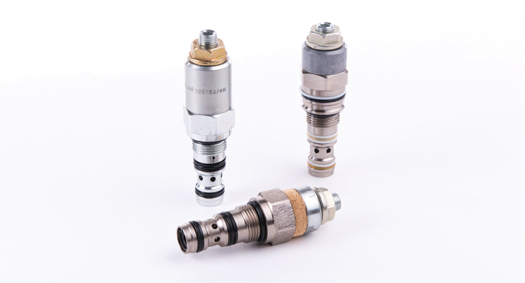
Solenoid directional valves and cartridges with inductive sensors to monitor the spool/poppet position, certified to Machine Directive 2006/42/EC. Pressure relief valves certified to PED 2014/68/EU.

Critical-application safety valves are functionally redundant, self-monitoring, and return to a safe position. It is easy to say that “Safety is everyone’s goal,” but what is really meant by that? Sound workplace safety practices can reduce the risk of injury to not only machine operators but to other people such as maintenance technicians; it can also reduce the risk that there is accidently damage to machinery and other company assets, or harm to the environment. Common industry standards acknowledge that there is no such thing as zero risk, while nonetheless providing guidance to machine builders and operators regarding how to take steps to minimize risks. This is commonly referred to as a machine safeguarding. Here’s a snapshot look at some key factors:
Alternative methods of controls offer two-time saving advantages. First, it uses a single lock-point (a remote, low-voltage system) that simplifies and speeds lockout, and enhances safety by avoiding the chance of a point being missed. The operator need not travel all around the machine to access various points to lockout or unlock operations. These systems place electrical lockout switches, connected to the control system, at locations that require machine access, and incorporate appropriate safety valves for pneumatic and hydraulic lockout.
The second feature of alternative lockout systems is not all energy needs to be removed. In fact, sometimes removing all the energy creates a more-hazardous condition. This can result in significant time and cost savings when systems contain large volumes of compressed air.
The standard is also useful for tasks that are not routine, repetitive, or integral to production, but require power for, say, troubleshooting a control circuit. The new standard recognizes that there is no such thing as zero risk, and that some risk is present in order to perform certain tasks. In this case, the standard requires that the control system and valve controlling the non-isolated energy be control-reliable, Category-3 or -4.
There is no such thing as “zero risk”. Therefore, the standards require that you assess all possible risks, and determine what possible ways can be accomplished for most-effectively reducing those risks. The best approach to risk assessment is as a team. One big change ANSI B11.TR3-2000 brought about is that both the machine manufacturer and user are responsible for performing the assessment for new and rebuilt machines. In the past, machine safety was considered the user’s responsibility. Perhaps the most difficult part is defining the subjective words for the assessment. There are no precise answers, and even the standards differ. Users need to develop their own risk assessment program.
Many companies hold that there are two degrees of injury: minor and major. Minor injuries can be treated with a first aid kit, and anything requiring more extensive care is considered a major injury for risk assessment purposes. When a company uses a risk matrix that leans toward the “better-to-be-safe” side, the first question is, of course, “Will it entail additional expense to eliminate a rare possibility?” But to error on the high side forces the assessment team to look more carefully at each hazard. Often, safety can pay back in machine up time, reduced employee absenteeism, saving the time and cost to investigate an accident, insurance savings, and other hidden costs involved with accidents. Safety is part of a company’s loss-prevention program.
Avoiding using the wrong category valve should be the primary concern when performing a risk assessment. For example, a circuit with a single valve that suffers a broken spring or a sticky spool would have a different fault result than a similar circuit employing a double valve experiencing a broken spring or sticky valve. ANSI B11.TR3-2000 sets the recommended minimum level of control integrity as follows.Highest degree of risk reduction - Control systems having redundancy with continuous self-checking to ensure continuous performance.
Ross Controls Offers and expanded technical reference book "Fluid Power Safety for Machine Guarding", and a course in Fluid Power Safety, "TOTAL MACHINE SAFETY".
ROSS valves for Safety-related applications are designed to meet many Global standards including the following: CSA, Australian AS, EN, ISO, OSHA, ANSI, & CE
PNOZmulti 2 are modular safety controllers: there are two base units and numerous expansion modules available for various application options. Application of the small controllers is particularly user-friendly with the freely configurable software tool. You can configure both the hardware and the necessary software functions directly in the tool.
We have developed the dual-pole semiconductor output module PNOZ m EF 8DI2DOT to monitor mechanical presses. It is used to actuate press safety valves, as well as other actuators that require dual-pole switching. PNOZ m EF 8DI2DOT has two safety outputs and eight digital inputs, for which a filter time can be configured. Benefit from short cycle times of approx. 3 ms and fast reaction times of under 8 ms. Press safety functions are quick and easy to configure with certified press blocks in the PNOZmulti Configurator!

As a hydraulic instructor and consultant, I have met thousands of people whose job consists, at least in part, of the maintenance and repair of hydraulic systems. The number of hydraulic troubleshooters I have come across, however, I can count on the fingers of one hand.
For the most part, I have encountered a lot of excellent hydraulic parts changers. These are people who have worked on and around hydraulic systems for so long that they know changing a specific part typically corrects a certain problem. They may or may not know exactly why this is, but they know from experience that replacing this part fixes the problem.
If I had to pick a single concept that keeps most parts changers from becoming troubleshooters, it would be the failure to understand the difference between pressure and flow. It is not uncommon to hear the terms used interchangeably, as though they are synonyms. They aren’t. I often hear the complaint that a pump isn’t putting out as much pressure as it should, implying that the pump is supposed to deliver pressure.
A common assumption is that if the pressure is low, the pump must be bad. This is not the case. The pump doesn’t pump pressure. The pump delivers a rate of flow. The single function of the pump is to take fluid from one place and put it somewhere else. Pressure is the result of resistance to flow. In our training classes, we use the simple schematic shown above to explain this concept.
A fixed-displacement pump is the simplest type of hydraulic pump. It is turned by a primary mover, generally an electric drive motor or, in mobile equipment, the same engine that moves the machine. The amount of flow is determined by the displacement and speed of the drive motor. By “displacement,” I mean the amount of fluid delivered for each full rotation of the pump.
If you trace the flow from the pump, you reach a “T” in the line. Whenever you follow the flow on a schematic and arrive at a line split, you must track the flow in both directions to determine the path of least resistance. Hydraulic fluid always takes the path of least resistance. I
f you trace the flow to the left, you encounter a relief valve symbol. The relief valve is represented by a single square with an arrow indicating the direction of flow. Notice the arrow does not touch the inlet or outlet port. This signifies that the relief valve is normally closed and blocking flow.
The “zigzag” line at the bottom of the relief valve symbolizes a spring. A good way to think of a relief valve in a schematic is to think of the spring pushing the arrow up away from the ports, holding it closed. This means that, in order to open the valve, something must push down on the arrow harder than the spring is pushing up.
Also, note the dotted line. In hydraulic schematics, a dotted line usually represents a flow path that is somewhat smaller than that of a solid line, typically a drain line or a pilot line. The one shown in the schematics on the left is a pilot line connected immediately upstream of the valve. Whatever pressure is in the main line will be present in the pilot line.
Returning to the spring, notice the diagonal arrow. In schematic symbols, a diagonal arrow means that its related component is variable or adjustable. In this case, the relief valve has an adjustable spring and has been adjusted so that a pressure of 500 pounds per square inch (psi) will develop enough force to compress the spring and open the relief valve. The resistance in this direction is therefore 500 psi.
Tracing the flow to the right, you encounter a symbol for a manual valve. This could be a ball valve, gate valve, butterfly valve, etc. The valve can be open or closed. The notation indicates that it is open, so there is no resistance in this direction.
The line terminates into an open drum. When the pump is turned on, as shown in the schematic on the left, the path of least resistance in this case is to the drum, not through the relief valve. The pressure reading on the gauge is 0 psi.
Clearly, the reason the gauge reads so low is because there is no resistance in the system. However, I have seen many pumps replaced for no other reason than because the pressure in the system was low. Over the years, I have received numerous phone calls that started out, “Well, I have changed the pump, but my pressure is still low. What else should I look for?”
In fact, a pressure problem in a hydraulic system is rarely the pump. It is almost always another bad component in the system. The pump should never be the first component to try but rather your last resort when a pressure problem exists. In the example shown, replacing the pump would deliver exactly the same result.
In the schematic on the left, the manual valve has been closed, blocking flow to the drum. The only remaining flow path is through the relief valve. For fluid to pass through the relief valve, a resistance of 500 psi must be overcome. Once pressure builds to 500 psi, flow is delivered through the relief valve and back to the tank.
On many occasions, I have heard remarks such as, “My pump is putting out 1,500 psi.” This illustrates the misconception that pressure originates at the pump.
As you can see, what is being read on the gauge is not how much pressure the pump is putting out but rather the amount of resistance currently being overcome in the system. Without a firm understanding of this concept, becoming a troubleshooter is impossible.
Jack Weeks is a hydraulic instructor and consultant for GPM Hydraulic Consulting. Since 1997 he has trained thousands of electricians and mechanics in hydraulic troubleshooting methods. Jack has...


 8613371530291