
improved high lift safety valve price
There is a wide range of safety valves available to meet the many different applications and performance criteria demanded by different industries. Furthermore, national standards define many varying types of safety valve.
The ASME standard I and ASME standard VIII for boiler and pressure vessel applications and the ASME/ANSI PTC 25.3 standard for safety valves and relief valves provide the following definition. These standards set performance characteristics as well as defining the different types of safety valves that are used:
ASME I valve - A safety relief valve conforming to the requirements of Section I of the ASME pressure vessel code for boiler applications which will open within 3% overpressure and close within 4%. It will usually feature two blowdown rings, and is identified by a National Board ‘V’ stamp.
ASME VIII valve- A safety relief valve conforming to the requirements of Section VIII of the ASME pressure vessel code for pressure vessel applications which will open within 10% overpressure and close within 7%. Identified by a National Board ‘UV’ stamp.
Full bore safety valve - A safety valve having no protrusions in the bore, and wherein the valve lifts to an extent sufficient for the minimum area at any section, at or below the seat, to become the controlling orifice.
Conventional safety relief valve -The spring housing is vented to the discharge side, hence operational characteristics are directly affected by changes in the backpressure to the valve.
Balanced safety relief valve -A balanced valve incorporates a means of minimising the effect of backpressure on the operational characteristics of the valve.
Pilot operated pressure relief valve -The major relieving device is combined with, and is controlled by, a self-actuated auxiliary pressure relief device.
Power-actuated safety relief valve - A pressure relief valve in which the major pressure relieving device is combined with, and controlled by, a device requiring an external source of energy.
Standard safety valve - A valve which, following opening, reaches the degree of lift necessary for the mass flowrate to be discharged within a pressure rise of not more than 10%. (The valve is characterised by a pop type action and is sometimes known as high lift).
Full lift (Vollhub) safety valve -A safety valve which, after commencement of lift, opens rapidly within a 5% pressure rise up to the full lift as limited by the design. The amount of lift up to the rapid opening (proportional range) shall not be more than 20%.
Direct loaded safety valve -A safety valve in which the opening force underneath the valve disc is opposed by a closing force such as a spring or a weight.
Proportional safety valve - A safety valve which opens more or less steadily in relation to the increase in pressure. Sudden opening within a 10% lift range will not occur without pressure increase. Following opening within a pressure of not more than 10%, these safety valves achieve the lift necessary for the mass flow to be discharged.
Diaphragm safety valve -A direct loaded safety valve wherein linear moving and rotating elements and springs are protected against the effects of the fluid by a diaphragm
Bellows safety valve - A direct loaded safety valve wherein sliding and (partially or fully) rotating elements and springs are protected against the effects of the fluids by a bellows. The bellows may be of such a design that it compensates for influences of backpressure.
Controlled safety valve - Consists of a main valve and a control device. It also includes direct acting safety valves with supplementary loading in which, until the set pressure is reached, an additional force increases the closing force.
Safety valve - A safety valve which automatically, without the assistance of any energy other than that of the fluid concerned, discharges a quantity of the fluid so as to prevent a predetermined safe pressure being exceeded, and which is designed to re-close and prevent further flow of fluid after normal pressure conditions of service have been restored. Note; the valve can be characterised either by pop action (rapid opening) or by opening in proportion (not necessarily linear) to the increase in pressure over the set pressure.
Direct loaded safety valve -A safety valve in which the loading due to the fluid pressure underneath the valve disc is opposed only by a direct mechanical loading device such as a weight, lever and weight, or a spring.
Assisted safety valve -A safety valve which by means of a powered assistance mechanism, may additionally be lifted at a pressure lower than the set pressure and will, even in the event of a failure of the assistance mechanism, comply with all the requirements for safety valves given in the standard.
Supplementary loaded safety valve - A safety valve that has, until the pressure at the inlet to the safety valve reaches the set pressure, an additional force, which increases the sealing force.
Note; this additional force (supplementary load), which may be provided by means of an extraneous power source, is reliably released when the pressure at the inlet of the safety valve reaches the set pressure. The amount of supplementary loading is so arranged that if such supplementary loading is not released, the safety valve will attain its certified discharge capacity at a pressure not greater than 1.1 times the maximum allowable pressure of the equipment to be protected.
Pilot operated safety valve -A safety valve, the operation of which is initiated and controlled by the fluid discharged from a pilot valve, which is itself, a direct loaded safety valve subject to the requirement of the standard.
The common characteristic shared between the definitions of conventional safety valves in the different standards, is that their operational characteristics are affected by any backpressure in the discharge system. It is important to note that the total backpressure is generated from two components; superimposed backpressure and the built-up backpressure:
Subsequently, in a conventional safety valve, only the superimposed backpressure will affect the opening characteristic and set value, but the combined backpressure will alter the blowdown characteristic and re-seat value.
The ASME/ANSI standard makes the further classification that conventional valves have a spring housing that is vented to the discharge side of the valve. If the spring housing is vented to the atmosphere, any superimposed backpressure will still affect the operational characteristics. Thiscan be seen from Figure 9.2.1, which shows schematic diagrams of valves whose spring housings are vented to the discharge side of the valve and to the atmosphere.
By considering the forces acting on the disc (with area AD), it can be seen that the required opening force (equivalent to the product of inlet pressure (PV) and the nozzle area (AN)) is the sum of the spring force (FS) and the force due to the backpressure (PB) acting on the top and bottom of the disc. In the case of a spring housing vented to the discharge side of the valve (an ASME conventional safety relief valve, see Figure 9.2.1 (a)), the required opening force is:
In both cases, if a significant superimposed backpressure exists, its effects on the set pressure need to be considered when designing a safety valve system.
Once the valve starts to open, the effects of built-up backpressure also have to be taken into account. For a conventional safety valve with the spring housing vented to the discharge side of the valve, see Figure 9.2.1 (a), the effect of built-up backpressure can be determined by considering Equation 9.2.1 and by noting that once the valve starts to open, the inlet pressure is the sum of the set pressure, PS, and the overpressure, PO.
Balanced safety valves are those that incorporate a means of eliminating the effects of backpressure. There are two basic designs that can be used to achieve this:
Although there are several variations of the piston valve, they generally consist of a piston type disc whose movement is constrained by a vented guide. The area of the top face of the piston, AP, and the nozzle seat area, AN, are designed to be equal. This means that the effective area of both the top and bottom surfaces of the disc exposed to the backpressure are equal, and therefore any additional forces are balanced. In addition, the spring bonnet is vented such that the top face of the piston is subjected to atmospheric pressure, as shown in Figure 9.2.2.
The bellows arrangement prevents backpressure acting on the upper side of the disc within the area of the bellows. The disc area extending beyond the bellows and the opposing disc area are equal, and so the forces acting on the disc are balanced, and the backpressure has little effect on the valve opening pressure.
Bellows failure is an important concern when using a bellows balanced safety valve, as this may affect the set pressure and capacity of the valve. It is important, therefore, that there is some mechanism for detecting any uncharacteristic fluid flow through the bellows vents. In addition, some bellows balanced safety valves include an auxiliary piston that is used to overcome the effects of backpressure in the case of bellows failure. This type of safety valve is usually only used on critical applications in the oil and petrochemical industries.
Since balanced pressure relief valves are typically more expensive than their unbalanced counterparts, they are commonly only used where high pressure manifolds are unavoidable, or in critical applications where a very precise set pressure or blowdown is required.
This type of safety valve uses the flowing medium itself, through a pilot valve, to apply the closing force on the safety valve disc. The pilot valve is itself a small safety valve.
The diaphragm type is typically only available for low pressure applications and it produces a proportional type action, characteristic of relief valves used in liquid systems. They are therefore of little use in steam systems, consequently, they will not be considered in this text.
The piston type valve consists of a main valve, which uses a piston shaped closing device (or obturator), and an external pilot valve. Figure 9.2.4 shows a diagram of a typical piston type, pilot operated safety valve.
The piston and seating arrangement incorporated in the main valve is designed so that the bottom area of the piston, exposed to the inlet fluid, is less than the area of the top of the piston. As both ends of the piston are exposed to the fluid at the same pressure, this means that under normal system operating conditions, the closing force, resulting from the larger top area, is greater than the inlet force. The resultant downward force therefore holds the piston firmly on its seat.
If the inlet pressure were to rise, the net closing force on the piston also increases, ensuring that a tight shut-off is continually maintained. However, when the inlet pressure reaches the set pressure, the pilot valve will pop open to release the fluid pressure above the piston. With much less fluid pressure acting on the upper surface of the piston, the inlet pressure generates a net upwards force and the piston will leave its seat. This causes the main valve to pop open, allowing the process fluid to be discharged.
When the inlet pressure has been sufficiently reduced, the pilot valve will reclose, preventing the further release of fluid from the top of the piston, thereby re-establishing the net downward force, and causing the piston to reseat.
Pilot operated safety valves offer good overpressure and blowdown performance (a blowdown of 2% is attainable). For this reason, they are used where a narrow margin is required between the set pressure and the system operating pressure. Pilot operated valves are also available in much larger sizes, making them the preferred type of safety valve for larger capacities.
One of the main concerns with pilot operated safety valves is that the small bore, pilot connecting pipes are susceptible to blockage by foreign matter, or due to the collection of condensate in these pipes. This can lead to the failure of the valve, either in the open or closed position, depending on where the blockage occurs.
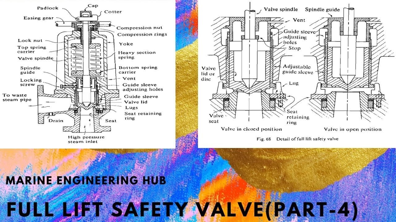
The terms full lift, high lift and low lift refer to the amount of travel the disc undergoes as it moves from its closed position to the position required to produce the certified discharge capacity, and how this affects the discharge capacity of the valve.
A full lift safety valve is one in which the disc lifts sufficiently, so that the curtain area no longer influences the discharge area. The discharge area, and therefore the capacity of the valve are subsequently determined by the bore area. This occurs when the disc lifts a distance of at least a quarter of the bore diameter. A full lift conventional safety valve is often the best choice for general steam applications.
The disc of a high lift safety valve lifts a distance of at least 1/12th of the bore diameter. This means that the curtain area, and ultimately the position of the disc, determines the discharge area. The discharge capacities of high lift valves tend to be significantly lower than those of full lift valves, and for a given discharge capacity, it is usually possible to select a full lift valve that has a nominal size several times smaller than a corresponding high lift valve, which usually incurs cost advantages.Furthermore, high lift valves tend to be used on compressible fluids where their action is more proportional.
In low lift valves, the disc only lifts a distance of 1/24th of the bore diameter. The discharge area is determined entirely by the position of the disc, and since the disc only lifts a small amount, the capacities tend to be much lower than those of full or high lift valves.
Except when safety valves are discharging, the only parts that are wetted by the process fluid are the inlet tract (nozzle) and the disc. Since safety valves operate infrequently under normal conditions, all other components can be manufactured from standard materials for most applications. There are however several exceptions, in which case, special materials have to be used, these include:
Cast steel -Commonly used on higher pressure valves (up to 40 bar g). Process type valves are usually made from a cast steel body with an austenitic full nozzle type construction.
For all safety valves, it is important that moving parts, particularly the spindle and guides are made from materials that will not easily degrade or corrode. As seats and discs are constantly in contact with the process fluid, they must be able to resist the effects of erosion and corrosion.
The spring is a critical element of the safety valve and must provide reliable performance within the required parameters. Standard safety valves will typically use carbon steel for moderate temperatures. Tungsten steel is used for higher temperature, non-corrosive applications, and stainless steel is used for corrosive or clean steam duty. For sour gas and high temperature applications, often special materials such as monel, hastelloy and ‘inconel’ are used.
A key option is the type of seating material used. Metal-to-metal seats, commonly made from stainless steel, are normally used for high temperature applications such as steam. Alternatively, resilient discs can be fixed to either or both of the seating surfaces where tighter shut-off is required, typically for gas or liquid applications. These inserts can be made from a number of different materials, but Viton, nitrile or EPDM are the most common. Soft seal inserts are not generally recommended for steam use.
Standard safety valves are generally fitted with an easing lever, which enables the valve to be lifted manually in order to ensure that it is operational at pressures in excess of 75% of set pressure. This is usually done as part of routine safety checks, or during maintenance to prevent seizing. The fitting of a lever is usually a requirement of national standards and insurance companies for steam and hot water applications. For example, the ASME Boiler and Pressure Vessel Code states that pressure relief valves must be fitted with a lever if they are to be used on air, water over 60°C, and steam.
A test gag (Figure 9.2.7) may be used to prevent the valve from opening at the set pressure during hydraulic testing when commissioning a system. Once tested, the gag screw is removed and replaced with a short blanking plug before the valve is placed in service.
The amount of fluid depends on the particular design of safety valve. If emission of this fluid into the atmosphere is acceptable, the spring housing may be vented to the atmosphere – an open bonnet. This is usually advantageous when the safety valve is used on high temperature fluids or for boiler applications as, otherwise, high temperatures can relax the spring, altering the set pressure of the valve. However, using an open bonnet exposes the valve spring and internals to environmental conditions, which can lead to damage and corrosion of the spring.
When the fluid must be completely contained by the safety valve (and the discharge system), it is necessary to use a closed bonnet, which is not vented to the atmosphere. This type of spring enclosure is almost universally used for small screwed valves and, it is becoming increasingly common on many valve ranges since, particularly on steam, discharge of the fluid could be hazardous to personnel.
Some safety valves, most commonly those used for water applications, incorporate a flexible diaphragm or bellows to isolate the safety valve spring and upper chamber from the process fluid, (see Figure 9.2.9).
LEADER VALVES LIMITED is a leading valve manufacturing company of India. We are a totally integrated valves manufacturing unit with our own Ferrous & Non Ferrous Foundries, Forging units and state of the art Machining and Testing facilities.
The company was set- up seven decades ago when India was on the threshold of industrial revolution and there were no good valve manufacturers in the country. It has over the years built up an excellent track record by following the policy of customer satisfaction through continual improvement in Designs, Manufacturing Processes and marketing products that are highly competitive, Safe and Harmless to the environment.
We are an ISO-9001:2015 company since Jan 1996 certified by LRQA, India. The company is also licensed to use API Spec 6D and API 600 monograms. Our Ferrous & Non-Ferrous foundries are PED certified by M/s. LRQA India & AD 2000-Merkblatt WO certified by TUV India. The Foundries are also adjudged as "Well Known FOUNDRY" under Indian Boiler Regulation 4C(2) of Central Boiler Board, Govt. of India. We also have IRS works approval certificate for Ferrous and Non Ferrous Foundry for casting of marine valves in accordance with the relevant requirements of Part 2, Chapter 4 & Chapter 8 of "Rules & Regulations for the Construction & Classification of Steel Ships". Our valves are certified by "FCRI" for functional and structural integrity for Seismic applications.

We are renowned manufacturers of well designed and highly efficient Double Port Safety Valves. Demanded by modern plants, our safety valves are capable of dealing with the pressure and temperature normally encountered in the steam process and compressed air. Our range of Double Port Safety Valves is as per the I.B.R guidelines . Our safety valves have a heat and corrosion resistant chrome alloy trim and are also top guided to ensure discharge capabilities. Moreover the carefully lapped flat faces of valve and seat to optical precision, guarantee pressure tightness and minimum size for the given duties.

Surface-controlled subsurface safety valves (SCSSVs) are critical components of well completions, preventing uncontrolled flow in the case of catastrophic damage to wellhead equipment. Fail-safe closure must be certain to ensure proper security of the well. However, this is not the only function in which it must be reliable—the valve must remain open to produce the well. Schlumberger surface controlled subsurface safety valves exceed all ISO 10432 and API Spec 14A requirements for pressure integrity, leakage acceptance criteria, and slam closure.
Through decades of innovation and experience, Schlumberger safety valve flapper systems are proven robust and reliable. The multizone dynamic seal technology for hydraulic actuation of subsurface safety valves is a further improvement in reliability performance when compared with traditional seal systems in the industry.
The multizone seal technology is currently available in the GeoGuard high-performance deepwater safety valves, which is validated to API Spec 14A V1 and V1-H.
Earlier, marine boilers were primarily installed on a ship for the propulsion plant, which used to run on steam (steam engine). Today, the steam generated by the boiler is utilized in various systems in the engine room, including heating of fuel for the main engine. Considering the importance of marine boilers and the risks involved with its operation on ships, there has been constant development in the industry to enhance boiler safety on board. Some even consider it one of the “deadliest” machinery systems on board.
Scalding: Scalding is a type of burn caused by high-temperature steam. Steam burn is one of the most common accidents seafarers experience on board. It is said that 8 out of 10 seamen, who work with the steam system, have experienced scalding (major or minor) in their careers at least once.
Hot Surface: The boiler and the associated pipes, valves, and auxiliaries have a very hot surface as they carry steam to different parts of the ship. A direct skin contact with any of the exposed surface will lead to severe burn.
Other Risks: Other risks such as high pressurized parts, handling harmful chemicals, moving machinery etc. are also associated with operating marine boilers.
Needless to say, safety is a critical aspect when operating a high or even a low-pressure boiler on a ship and therefore different marine boiler devices are provided.
Boiler Safety System and Instruments: A modern marine boiler is fitted with several safety devices for the protection of the operator. For easy understanding, let us divide these instruments/devices as per the system they are fitted in –
Steam Safety System: The steam system in the boiler is a high pressure, high-temperature area. To safeguard the operator and the boiler itself, it is fitted with the following safety features:
Safety Valve: Boiler safety valve is an extremely important safety equipment fitted on the steam drum of the boiler. As per SOLAS chapter II-1, every steam boiler and every un-fired steam generator shall be provided with not less than 2 safety valves of adequate capacity. However, with regards to the output or any other feature of a boiler or un-fired steam generator, the administration may permit only one safety valve to be fitted if adequate protection against overpressure is thereby satisfactorily provided.
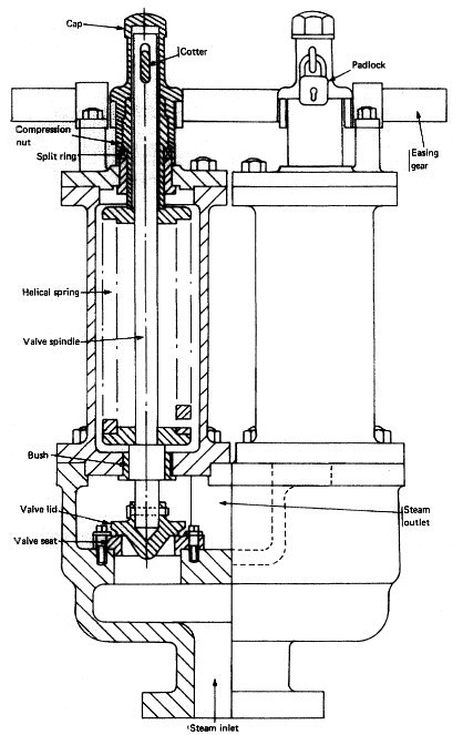
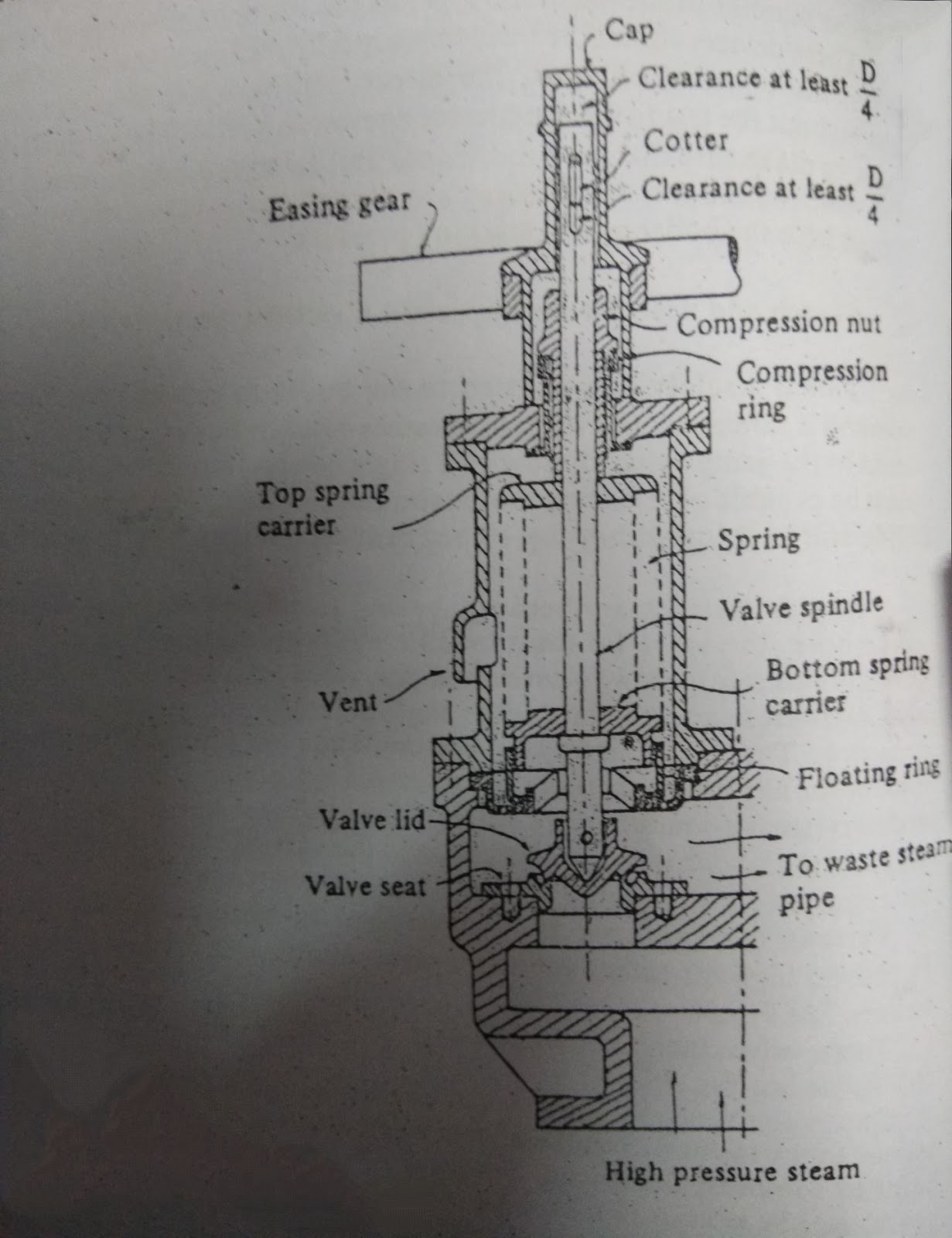
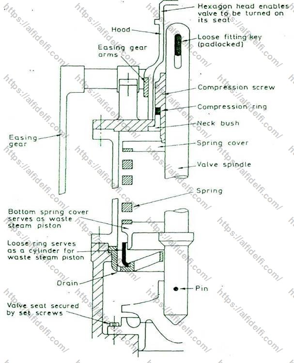
Usually, an improved high lift is one of the most popular types of safety valves used on a ship. They are set to lift at the blow-off pressure and shut when the pressure reduces to the safe limit. They are set to open at 3 % above working pressure. The lift of valve is one-twelfth of the valve diameter.
Easing Gear: The easing gear is attached to the boiler safety valve. Every individual safety valve is provided with its own easing gear, which is a pulley and wire arrangement (connected to the lever of the safety valve) with an accessible handle at the lower operating boiler platform. It is used to lift the boiler safety valve in case of an emergency (without getting near to the safety valve) and to regularly test the operation of the safety valves.
Steam Pressure Alarm and cutout: An audio-visual alarm is also provided for the steam pressure system to remind the operator about the steam pressure. Once the alarm activates and the pressure continues to rise (or decrease), the cut-out will get activated and it will shut off the fuel burner. The cutout functioning is different and independent of the automation which operates the burner. The low-pressure cutout has an option to override it, but the high-pressure cutout will stop the burner and should never be overridden in any case
Water Safety System: The water system is a high-temperature system and the level and quality of the water inside the water drum plays a crucial role in the safe operation of the boiler. Following are the equipment/system fitted on the water side of the marine boiler:
Low / high water level alarm and cutout: The boiler water drum is fitted with a level sensor, which will continuously monitor the level of water inside the drum. A full drum will carry over the water or will have no space to generate steam, thus reducing the efficiency of the boiler; whereas low or no water level in the drum will lead to over-heating of tubes and can lead to fire or meltdown of the complete boiler.
The low/ high water level provides an early warning to the operator for taking appropriate action to manage the water level inside the boiler water drum.
Too low water level alarm and shut down: The initial warning provided by the above arrangement (low/high water level alarm), may not be sufficient for the operator as there can be a major leak in the tubes, leading to a reduction in the water level. A secondary safety is therefore provided i.e. Too low water level alarm and shut down, which will stop the burner firing to control the overheating of the boiler internal parts.
Water level indicators: The boiler is fitted with multiple water level indicators to make it easy for the operator to see the water drum level and ensure operational safety of the boiler.
Salinity Sensor: The boiler drum is fitted with a salinity sensor, which continuously monitors the dissolved solids content in the water. If the solid (e.g. salt) content exceeds the set value, it trips the boiler to ensure the tubes and boiler internals does not get affected due to the contamination. The operator should either blow down the boiler and feed fresh water to the drum to eliminate the cause which is resulting in high salinity (for e.g. leakage in the condenser)
Fuel Safety System: The boiler is provided with heavy or marine gas fuel oil for generating the heat in the furnace. To ensure the fuel system is operating efficiently, it is fitted with the following boiler safety features:
Low / high fuel oil temperature alarm: Modern marine boilers are meant to operate in different grades of fuel due to the port / ECA regulations for minimizing the air pollution from the ship. The oil temperature is an important factor as it controls the viscosity of the fuel which is directly related to atomization and efficient combustion inside the furnace. If the fuel temperature is not at its set value (which will vary for different grades), the alarm will sound. The operator must stop the alarm and the oil temperature should be brought to normal before restarting the boiler.
Smoke Density alarm: With more stringent rules coming up for environmental protection, the boiler exhaust is fitted with a smoke density sensor which detects the post-combustion product, especially during starting of a boiler and at low loads. If the smoke density is higher than the required value, it will sound an alarm to which the operator needs to check the combustion of the boiler
Operational Safety: Automation, alarms, and warnings have made the life of seafarers on ships a lot easier than what it used to be in terms of boiler safety. However, professional engineers rarely depend on them and always rely on the best practice for efficiently running the machinery.
Lagging: Once the steam comes out of the boiler via main steam stop valve, it is supplied to several systems via pipes and distribution valves. A proper lagging on the pipes and valves will ensure the boiler need not run extra as the steam loss will be contained. Also, it ensures the safety of ship staff from surface burns.
Maintenance: On-time maintenance such as testing of safety valve, cleaning of boiler tubes etc. will result in safe and efficient working of the marine boiler.

Fluidyne Boiler Full Lift Full Flow Safety Relief Valve is a high performance valve designed and developed for steam and water service. It can also be used for most other applications like gases and vapors, saturated steam, superheated steam. Fluidyne Safety Relief Valve is designed for steam service. The valves are designed as per API 520, API 526 and meets the requirements of ASME Sec VIII-Division I. Fluidyne Boiler Safety Valves are offered with IBR Certification in Form III-C. The valves have a full nozzle or half nozzle and guided at the guide of the valve body, increasing the eficiency of the valve assembly. Specially designed disc holder ensures full lift within 5% to 10% overpressure or increase of pressure above the set pressure value. Blow down of a maximum of 5% to 10% is achieved in this design. Lapping of valve seat to optical flatness ensures leak tightness at seat. Full lift of valve disc ensures that the certified flow of the safety valve is discharged. Spring made of chrome vanadium steel is precisely selected and assembled so that the valve operates precisely and a good leak tightness is achieved at high temperatures with great repeatability.

A safety valve is a valve that acts as a fail-safe. An example of safety valve is a pressure relief valve (PRV), which automatically releases a substance from a boiler, pressure vessel, or other system, when the pressure or temperature exceeds preset limits. Pilot-operated relief valves are a specialized type of pressure safety valve. A leak tight, lower cost, single emergency use option would be a rupture disk.
Safety valves were first developed for use on steam boilers during the Industrial Revolution. Early boilers operating without them were prone to explosion unless carefully operated.
Vacuum safety valves (or combined pressure/vacuum safety valves) are used to prevent a tank from collapsing while it is being emptied, or when cold rinse water is used after hot CIP (clean-in-place) or SIP (sterilization-in-place) procedures. When sizing a vacuum safety valve, the calculation method is not defined in any norm, particularly in the hot CIP / cold water scenario, but some manufacturers

A safety valve is a valve that acts as a protection of equipment from exploding or damaging and it is mainly installed in pressure vessels such as chemical plants, electric power boilers, and gas storage tanks.
Safety Relief Valve is a type of valve that automatically actuates when the pressure of inlet side of the valve increases to a predetermined pressure, to open the valve disc and discharge the fluid (steam or gas); and when the pressure decreases to the prescribed value, to close the valve disc again.
There are a number of reasons why the pressure in a vessel or equipment can exceed a predetermined limit. The most common are: Blocked outlet; Exposure to external fire, often referred to as “Fire Case”; Thermal expansion of fluid; Abnormal process conditions (Chemical reaction); Cooling system failure; Heat exchanger tube rupture; Pipework component failure; Control Valve failure, etc.
Each of the above-listed events may occur individually or simultaneously. Every cause of over-pressure will create a different mass or volume flow to be discharged. For e.g. small mass flow for thermal expansion and large mass flow in case of a chemical reaction. It is the process engineer’s responsibility to determine the most worst-case scenario for the sizing and selection of a suitable pressure safety device.
Relief valve: A spring-loaded pressure-relief valve actuated by the static pressure upstream of the valve. The valve opens normally in proportion to the pressure increase over the opening pressure. A relief valve is used primarily with incompressible fluids such as any Liquid.
Safety valve: A spring-loaded pressure-relief valve actuated by the static pressure upstream of the valve and characterized by rapid opening or pop action. A safety valve is normally used with compressible fluids such as any Gases, Steam.
The terms full lift, high lift, and low lift refer to the amount of travel the disc undergoes as it moves from its closed position to the position required to produce the certified discharge capacity, and how this affects the discharge capacity of the valve.
A full lift safety valve is one in which the disc lifts sufficiently so that the curtain area no longer influences the discharge area. The discharge area, and therefore the capacity of the valve are subsequently determined by the bore area. This occurs when the disc lifts a distance of at least a quarter of the bore diameter. A full lift conventional safety valve is often the best choice for general steam applications.
The disc of a high lift safety valve lifts a distance of at least 1/12th of the bore diameter. This means that the curtain area, and ultimately the position of the disc, determines the discharge area. The discharge capacities of high lift valves tend to be significantly lower than those of full lift valves, and for a given discharge capacity, it is usually possible to select a full lift valve that has a nominal size several times smaller than a corresponding high lift valve, which usually incurs cost advantages. Furthermore, high lift valves tend to be used on compressible fluids where their action is more proportional.
In low lift valves, the disc only lifts a distance of 1/24th of the bore diameter. The discharge area is determined entirely by the position of the disc, and since the disc only lifts a small amount, the capacities tend to be much lower than those of full or high lift valves.
A conventional safety Relief Valve is a pressure Relief Valve which has its spring housing vented to the discharge side of the Valve. The operational characteristics (opening pressure, closing pressure, and relieving capacity) are directly affected by changes of the back pressure on the Valve.
A balanced safety Relief Valve is a pressure Relief Valve which incorporates means of minimizing the effect of back pressure on the operational characteristics (opening pressure, closing pressure, and relieving capacity).
A pilot-operated pressure Relief Valve is a pressure Relief Valve in which the major relieving device is combined with and is controlled by a self-actuated auxiliary pressure Relief Valve.
A power-actuated pressure Relief Valve is a pressure Relief Valve in which the major relieving device is combined with and controlled by a device requiring an external source of energy.
A temperature-actuated pressure Relief Valve is a pressure Relief Valve that may be actuated by external or internal temperature or by pressure on the inlet side.
A vacuum Relief Valve is a pressure relief device designed to admit fluid to prevent an excessive internal vacuum; it is designed to reclose and prevent further flow of fluid after normal conditions have been restored.
Actual discharge area or actual orifice area: The area of a pressure-relief valve (PRV) is the minimum net area that determines the flow through a valve.
Blowdown: The difference between the set pressure and the closing pressure of a pressure-relief valve, expressed as a percentage of the set pressure or in pressure units.
Closing pressure: The value of decreasing inlet static pressure at which the valve disc re-establishes contact with the seat or at which lift becomes zero as determined by seeing, feeling, or hearing.
Cold differential test pressure (CDTP): The pressure at which a pressure-relief valve is adjusted to open on the test stand. The CDTP includes corrections for the service conditions of backpressure or temperature or both.
Curtain area: The area of the cylindrical or conical discharge opening between the seating surfaces above the nozzle seat created by the lift of the disc.
Opening pressure: The value of increasing inlet static pressure at which there is a measurable lift of the disc or at which discharge of the fluid becomes continuous, as determined by seeing, feeling, or hearing.
Pressure-relief device (PRD): A device actuated by inlet static pressure and designed to open during an emergency or abnormal conditions to prevent a rise of internal fluid pressure in excess of specified design value. The device also may be designed to prevent an excessive internal vacuum. The device may be a pressure-relief valve, a non-reclosing pressure-relief device, or a vacuum relief valve.
Conventional pressure-relief valve: A spring-loaded pressure-relief valve whose operational characteristics are directly affected by changes in the backpressure.
Balanced pressure-relief valve: A spring-loaded pressure-relief valve that incorporates a bellows or other means for minimizing the effect of backpressure on the operational characteristics of the valve.
Modulating pressure-relief valve: A pressure-relief valve that opens and flows in proportion to the inlet pressure for some or all parts of the valve’s operating range from set pressure to overpressure at full lift.
Pilot-operated pressure-relief valve: A pressure-relief valve in which the major relieving device or main valve is combined with and controlled by a self-actuated auxiliary pressure-relief valve (pilot).
A fire-tube boiler can be fitted with one or more safety valves on the top of its shell, with each set to open when the boiler reaches its design pressure. Noisolation valvesor restrictions should be integrated between the safety valve(s) and boiler. If the valves are not installed directly onto the boiler shell, the pipework connecting the valves to the boiler must be kept clear of blockagesand water, and this must be confirmed by periodic testing.
Once a safety valve opens, steam is discharged via the exhaust pipe. Exhaust pipes must be designed to encounter as few bends as possible, be as short as possible, to have no reduction in pipe section (no internal pipe diameter reduction), and should lead to asafe point of discharge(typically outside the boiler house).
Water must be drained from the safety valve or exhaust pipework via a drainpipe. Drainpipes may be connected to holes drilled into the lowest section of the exhaust pipework, or, directly to drain holes in the safety valve body; these drains are not to be confused with the blowdown ring locking bolt, if one is fitted.
Where two safety valves are fitted, it is common that one is set just belowthe boiler’s design pressure. It is vital that each safety valve permits the full flow of steam produced when the boiler is operating at maximum capacity i.e. when the boiler is producing the maximum amount of steam it can possibly produce. If safety valves are sized correctly, a boiler can be firing at full capacity without the steam pressure exceeding design limits (because the safety valve(s) relieves pressure at a faster rate than it is accumulated).
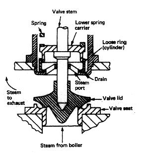
There are various types of safety valve, including high lift and improved high lift valves, which use the force of escaping steam to open a winged valve plug to achieve greater steam flow rates. In addition to this, some valves integrate a pistonat the bottom of the spring chamber. The piston has a larger surface area than the valve plug, which leads to the valve opening with a definitive ‘pop’ sound.
Some boiler safety valves include a blowdown ring. The blowdown ring can raise or lower the valve seat ring and is used to control the amount of blowdown through the valve. This ring is locked by a bolt that protrudes through the valve and into the adjusting ring segments.
Boiler safety valves should be fitted with an easing gear (looks like a handle), used, when necessary, to rapidly release boiler pressure. Easing gears can also be used for testing a safety valve, ensuring the spindle has freedom of movement and that the valve operating mechanism functions as intended. Easing gear testing is often not conducted due to operators having difficulty with the valves resealing, but this is generally only the case with valves that are not tested often enough. Actuating the easing gear several times is often all it takes to dislodge debris from the sealing area and allow the valve to seal again. For safe operation, the easing gear handle is usually connected via steel cables to an area neighbouring the boiler.
Like pressure gauges, all safety valves should be stripped, inspected, and calibrated, at least once a year; maintenance usually occurs during statutory inspections. Calibration of each valve should be conducted by a competent person, and any valve adjustment (including the blowdown ring) should be approved and sealed by the authorised inspector. After testing and calibration, all valves should be correctly marked, suitable certificates issued, and accurate records maintained.
An accumulation test can be conducted to ensure a safety valve can relieve over-pressure steam when the boiler burner is operating at maximum capacity. Accumulation testing of safety valves must be repeated after any alterations are made to the boiler e.g. replacement of a safety valve, fuel change, or changes to the control system. If, during an accumulation test, boiler pressure rises by more than 10% of its design pressure, the test must be aborted. Before the boiler is re-tested, amendments must be made to either the safety valve relieving capacity, thesafety valve exhaust pipework, or the boiler’s steaming capacity, to ensure the 10% limit is never exceeded.
Reliefand safetyvalves prevent equipment damage by relieving over-pressurisation of fluid systems. The main difference between a relief valve and a safety valve is the extent of opening at the set-point pressure.
A relief valve gradually opens as the inlet pressure increases above the set-point. A relief valve opens only as necessary to relieve the over-pressure condition. Relief valves are typically used for liquid systems.
A safety valve rapidly‘pops’ fully openas soon as the pressure setting is reached and will stay fully open until the pressure drops below the reset pressure. The reset pressure is lower than the actuating set-point pressure. The difference between the actuating pressure set-point, and the pressure at which the safety valve resets, is called blowdown. Safety valves are typically used for gas or vapour systems.
A safety relief valve may open fully, or proportionally, once the pressure setting is reached. SRVs may be used for any fluid system (gas, liquid, or vapour).

A safety valve is a valve that acts as a fail-safe. An example of safety valve is a pressure relief valve (PRV), which automatically releases a substance from a boiler, pressure vessel, or other system, when the pressure or temperature exceeds preset limits. Pilot-operated relief valves are a specialized type of pressure safety valve. A leak tight, lower cost, single emergency use option would be a rupture disk.
Safety valves were first developed for use on steam boilers during the Industrial Revolution. Early boilers operating without them were prone to explosion unless carefully operated.
Vacuum safety valves (or combined pressure/vacuum safety valves) are used to prevent a tank from collapsing while it is being emptied, or when cold rinse water is used after hot CIP (clean-in-place) or SIP (sterilization-in-place) procedures. When sizing a vacuum safety valve, the calculation method is not defined in any norm, particularly in the hot CIP / cold water scenario, but some manufacturers
The earliest and simplest safety valve was used on a 1679 steam digester and utilized a weight to retain the steam pressure (this design is still commonly used on pressure cookers); however, these were easily tampered with or accidentally released. On the Stockton and Darlington Railway, the safety valve tended to go off when the engine hit a bump in the track. A valve less sensitive to sudden accelerations used a spring to contain the steam pressure, but these (based on a Salter spring balance) could still be screwed down to increase the pressure beyond design limits. This dangerous practice was sometimes used to marginally increase the performance of a steam engine. In 1856, John Ramsbottom invented a tamper-proof spring safety valve that became universal on railways. The Ramsbottom valve consisted of two plug-type valves connected to each other by a spring-laden pivoting arm, with one valve element on either side of the pivot. Any adjustment made to one of valves in an attempt to increase its operating pressure would cause the other valve to be lifted off its seat, regardless of how the adjustment was attempted. The pivot point on the arm was not symmetrically between the valves, so any tightening of the spring would cause one of the valves to lift. Only by removing and disassembling the entire valve assembly could its operating pressure be adjusted, making impromptu "tying down" of the valve by locomotive crews in search of more power impossible. The pivoting arm was commonly extended into a handle shape and fed back into the locomotive cab, allowing crews to "rock" both valves off their seats to confirm they were set and operating correctly.
Safety valves also evolved to protect equipment such as pressure vessels (fired or not) and heat exchangers. The term safety valve should be limited to compressible fluid applications (gas, vapour, or steam).
For liquid-packed vessels, thermal relief valves are generally characterized by the relatively small size of the valve necessary to provide protection from excess pressure caused by thermal expansion. In this case a small valve is adequate because most liquids are nearly incompressible, and so a relatively small amount of fluid discharged through the relief valve will produce a substantial reduction in pressure.
Flow protection is characterized by safety valves that are considerably larger than those mounted for thermal protection. They are generally sized for use in situations where significant quantities of gas or high volumes of liquid must be quickly discharged in order to protect the integrity of the vessel or pipeline. This protection can alternatively be achieved by installing a high integrity pressure protection system (HIPPS).
In the petroleum refining, petrochemical, chemical manufacturing, natural gas processing, power generation, food, drinks, cosmetics and pharmaceuticals industries, the term safety valve is associated with the terms pressure relief valve (PRV), pressure safety valve (PSV) and relief valve.
The generic term is Pressure relief valve (PRV) or pressure safety valve (PSV). PRVs and PSVs are not the same thing, despite what many people think; the difference is that PSVs have a manual lever to open the valve in case of emergency.
Relief valve (RV): an automatic system that is actuated by the static pressure in a liquid-filled vessel. It specifically opens proportionally with increasing pressure
Pilot-operated safety relief valve (POSRV): an automatic system that relieves on remote command from a pilot, to which the static pressure (from equipment to protect) is connected
Low pressure safety valve (LPSV): an automatic system that relieves static pressure on a gas. Used when the difference between the vessel pressure and the ambient atmospheric pressure is small.
Vacuum pressure safety valve (VPSV): an automatic system that relieves static pressure on a gas. Used when the pressure difference between the vessel pressure and the ambient pressure is small, negative and near to atmospheric pressure.
Low and vacuum pressure safety valve (LVPSV): an automatic system that relieves static pressure on a gas. Used when the pressure difference is small, negative or positive and near to atmospheric pressure.
In most countries, industries are legally required to protect pressure vessels and other equipment by using relief valves. Also, in most countries, equipment design codes such as those provided by the ASME, API and other organizations like ISO (ISO 4126) must be complied with. These codes include design standards for relief valves and schedules for periodic inspection and testing after valves have been removed by the company engineer.
Today, the food, drinks, cosmetics, pharmaceuticals and fine chemicals industries call for hygienic safety valves, fully drainable and Cleanable-In-Place. Most are made of stainless steel; the hygienic norms are mainly 3A in the USA and EHEDG in Europe.
The first safety valve was invented by Denis Papin for his steam digester, an early pressure cooker rather than an engine.steelyard" lever a smaller weight was required, also the pressure could easily be regulated by sliding the same weight back and forth along the lever arm. Papin retained the same design for his 1707 steam pump.Greenwich in 1803, one of Trevithick"s high-pressure stationary engines exploded when the boy trained to operate the engine left it to catch eels in the river, without first releasing the safety valve from its working load.
Although the lever safety valve was convenient, it was too sensitive to the motion of a steam locomotive. Early steam locomotives therefore used a simpler arrangement of weights stacked directly upon the valve. This required a smaller valve area, so as to keep the weight manageable, which sometimes proved inadequate to vent the pressure of an unattended boiler, leading to explosions. An even greater hazard was the ease with which such a valve could be tied down, so as to increase the pressure and thus power of the engine, at further risk of explosion.
Although deadweight safety valves had a short lifetime on steam locomotives, they remained in use on stationary boilers for as long as steam power remained.
Weighted valves were sensitive to bouncing from the rough riding of early locomotives. One solution was to use a lightweight spring rather than a weight. This was the invention of Timothy Hackworth on his leaf springs.
These direct-acting spring valves could be adjusted by tightening the nuts retaining the spring. To avoid tampering, they were often shrouded in tall brass casings which also vented the steam away from the locomotive crew.
The Salter coil spring spring balance for weighing, was first made in Britain by around 1770.spring steels to make a powerful but compact spring in one piece. Once again by using the lever mechanism, such a spring balance could be applied to the considerable force of a boiler safety valve.
The spring balance valve also acted as a pressure gauge. This was useful as previous pressure gauges were unwieldy mercury manometers and the Bourdon gauge had yet to be invented.
Paired valves were often adjusted to slightly different pressures too, a small valve as a control measure and the lockable valve made larger and permanently set to a higher pressure, as a safeguard.Sinclair for the Eastern Counties Railway in 1859, had the valve spring with pressure scale behind the dome, facing the cab, and the locked valve ahead of the dome, out of reach of interference.
In 1855, John Ramsbottom, later locomotive superintendent of the LNWR, described a new form of safety valve intended to improve reliability and especially to be tamper-resistant. A pair of plug valves were used, held down by a common spring-loaded lever between them with a single central spring. This lever was characteristically extended rearwards, often reaching into the cab on early locomotives. Rather than discouraging the use of the spring lever by the fireman, Ramsbottom"s valve encouraged this. Rocking the lever freed up the valves alternately and checked that neither was sticking in its seat.
A drawback to the Ramsbottom type was its complexity. Poor maintenance or mis-assembly of the linkage between the spring and the valves could lead to a valve that no longer opened correctly under pressure. The valves could be held against their seats and fail to open or, even worse, to allow the valve to open but insufficiently to vent steam at an adequate rate and so not being an obvious and noticeable fault.Rhymney Railway, even though the boiler was almost new, at only eight months old.
Naylor valves were introduced around 1866. A bellcrank arrangement reduced the strain (percentage extension) of the spring, thus maintaining a more constant force.L&Y & NER.
All of the preceding safety valve designs opened gradually and had a tendency to leak a "feather" of steam as they approached "blowing-off", even though this was below the pressure. When they opened they also did so partially at first and didn"t vent steam quickly until the boiler was well over pressure.
The quick-opening "pop" valve was a solution to this. Their construction was simple: the existing circular plug valve was changed to an inverted "top hat" shape, with an enlarged upper diameter. They fitted into a stepped seat of two matching diameters. When closed, the steam pressure acted only on the crown of the top hat, and was balanced by the spring force. Once the valve opened a little, steam could pass the lower seat and began to act on the larger brim. This greater area overwhelmed the spring force and the valve flew completely open with a "pop". Escaping steam on this larger diameter also held the valve open until pressure had dropped below that at which it originally opened, providing hysteresis.
These valves coincided with a change in firing behaviour. Rather than demonstrating their virility by always showing a feather at the valve, firemen now tried to avoid noisy blowing off, especially around stations or under the large roof of a major station. This was mostly at the behest of stationmasters, but firemen also realised that any blowing off through a pop valve wasted several pounds of boiler pressure; estimated at 20 psi lost and 16 lbs or more of shovelled coal.
Pop valves derived from Adams"s patent design of 1873, with an extended lip. R. L. Ross"s valves were patented in 1902 and 1904. They were more popular in America at first, but widespread from the 1920s on.
Although showy polished brass covers over safety valves had been a feature of steam locomotives since Stephenson"s day, the only railway to maintain this tradition into the era of pop valves was the GWR, with their distinctive tapered brass safety valve bonnets and copper-capped chimneys.
Developments in high-pressure water-tube boilers for marine use placed more demands on safety valves. Valves of greater capacity were required, to vent safely the high steam-generating capacity of these large boilers.Naylor valve) became more critical.distilled feedwater and also a scouring of the valve seats, leading to wear.
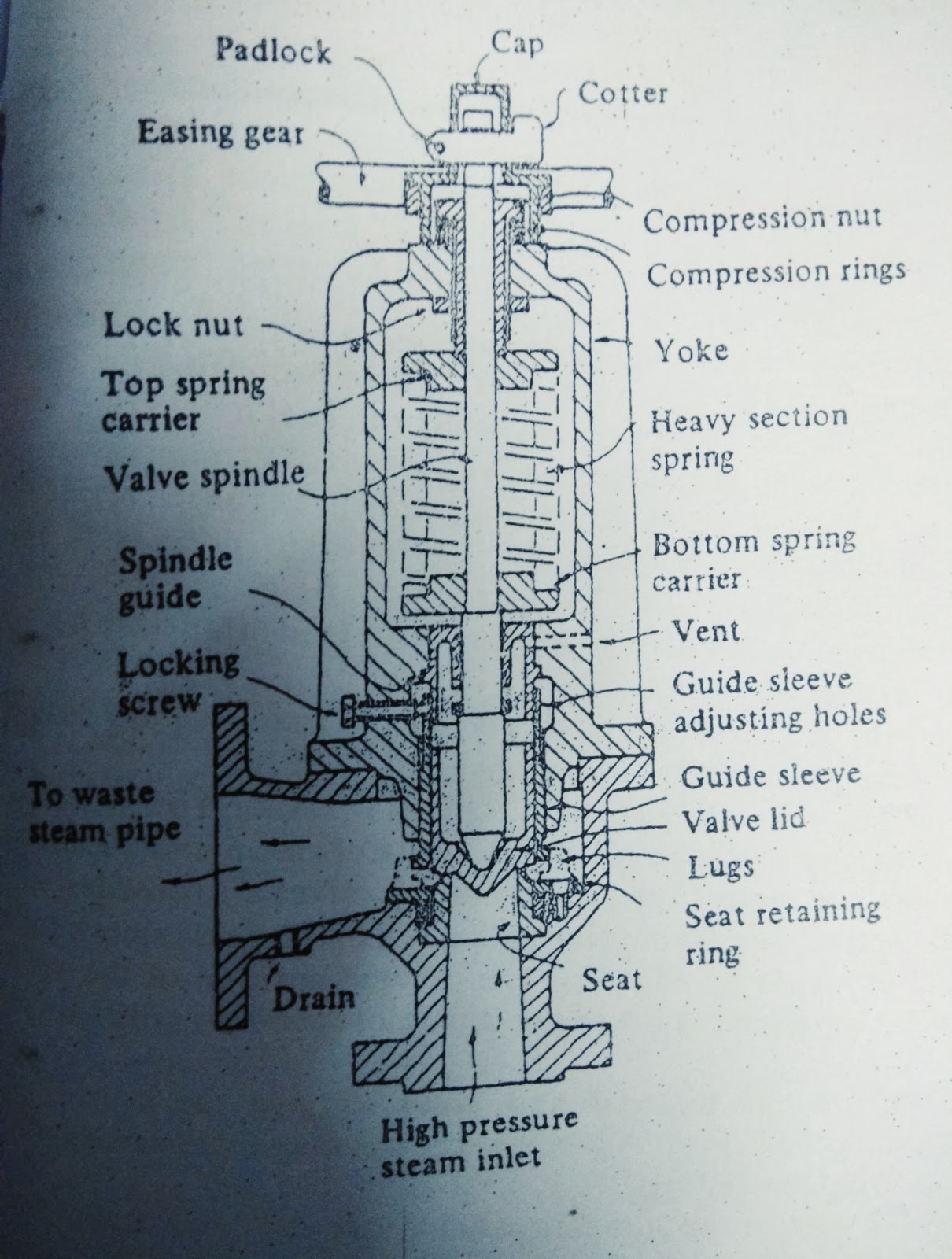
High-lift safety valves are direct-loaded spring types, although the spring does not bear directly on the valve, but on a guide-rod valve stem. The valve is beneath the base of the stem, the spring rests on a flange some height above this. The increased space between the valve itself and the spring seat allows the valve to lift higher, further clear of the seat. This gives a steam flow through the valve equivalent to a valve one and a half or twice as large (depending on detail design).
The Cockburn Improved High Lift design has similar features to the Ross pop type. The exhaust steam is partially trapped on its way out and acts on the base of the spring seat, increasing the lift force on the valve and holding the valve further open.
To optimise the flow through a given diameter of valve, the full-bore design is used. This has a servo action, where steam through a narrow control passage is allowed through if it passes a small control valve. This steam is then not exhausted, but is passed to a piston that is used to open the main valve.
There are safety valves known as PSV"s and can be connected to pressure gauges (usually with a 1/2" BSP fitting). These allow a resistance of pressure to be applied to limit the pressure forced on the gauge tube, resulting in prevention of over pressurisation. the matter that has been injected into the gauge, if over pressurised, will be diverted through a pipe in the safety valve, and shall be driven away from the gauge.
There is a wide range of safety valves having many different applications and performance criteria in different areas. In addition, national standards are set for many kinds of safety valves.
Safety valves are required on water heaters, where they prevent disaster in certain configurations in the event that a thermostat should fail. Such a valve is sometimes referred to as a "T&P valve" (Temperature and Pressure valve). There are still occasional, spectacular failures of older water heaters that lack this equipment. Houses can be leveled by the force of the blast.
Pressure cookers usually have two safety valves to prevent explosions. On older designs, one is a nozzle upon which a weight sits. The other is a sealed rubber grommet which is ejected in a controlled explosion if the first valve gets blocked. On newer generation pressure cookers, if the steam vent gets blocked, a safety spring will eject excess pressure and if that fails, the gasket will expand and release excess pressure downwards between the lid and the pan. Also, newer generation pressure cookers have a safety interlock which locks the lid when internal pressure exceeds atmospheric pressure, to prevent accidents from a sudden release of very hot steam, food and liquid, which would happen if the lid were to be removed when the pan is still slightly pressurised inside (however, the lid will be very hard or impossible to open when the pot is still pressurised).
NABIC have long been recognised as the industry standard for commercial and industrial safety and relief valves for hot water applications. NABIC products are all UK made with castings from the UK and Europe. NABIC products do not have castings from the far east as with many of its competitors.
Flowstar (UK) Limited (Company Number: 01384915, VAT Number: GB 475 448 317) is the largest worldwide stockist of NABIC safety valves and NABIC relief valves. Our NABIC prices are genuine discounts off the official NABIC list price. We have not increased our prices before discounting as on some websites. If you buy NABIC valves on a regular basis we can offer further discount and will price match were possible.
Returns: You need to tell us if you wish to return un-used goods within 14 days of purchase either by phone or email. You then have a further 14 days to return the goods back to us. We aim to process the refund within a few days of receiving them. Please note we charge a 20% restocking fee. This is to cover the work originally carried out setting and testing the valve and also the work we will need to do on its return to get it ready for resale.
The Nabic Fig 500ST High Lift Safety Valve is ideal for installations where the media / service fluid being used would normally necessitate a stainless steel valve, but where the working environment does not. It is suitable for use with hot water, steam, air, plus other media - please contact us for more information on which fluids are suitable. The valve comes supplied as a sealed dome unit or with a test lever, this high-quality valve is designed and tested to BS EN ISO 4126-1 standard.
To ensure quality and accuracy of set pressure, all Nabic 500ST valves are shell and seal tested before dispatch, and are fitted with a tamper-proof seal.
As standard, the superb Nabic 500ST features a tough and durable PTFE design with high seat tightness, along with stainless steel wetted parts with PTFE to metal seating. It incorporates diaphragm protected working parts and offers the user easy inspection and cleaning. The 500ST offers a range of additional features, including padlocks (compliant with M&E3), Viton seat design, and more.


 8613371530291