
kunkle safety valve catalog free sample

Kunkle Relief Valve OverviewWhen it comes to industrial and commercial safety and relief valve products, Kunkle’s valve’s catalog is second to none in steam, air, gas, and liquid applications.
Kunkle relief valves range in size from ¼” NPT to 6” flange and are suitable in cryogenic and high temperatures up to 800°F environments at vacuum to 7,500 psig pressure. Kunkle Valve’s code certifications meet several global and national board standards, including ASME Section I, Section IV, and Section VIII, PED, CRN, TU and Chinese, as well as non-code requirements.
Relief Valves for Steam ServiceSteam supplies heat for industrial and chemical processes and also is used to heat buildings, supply mechanical energy, and drive mechanical equipment. Steam moves from the boiler to the end point, then heats by direct heating or indirect heating through a heat exchanger. Kunkle steam relief valves are critical to protecting equipment such as boilers, steam lines, and pressure valves, from being over-pressurized.
Relief Valves for Air ServiceKunkle designs valves for air service, for example for air compressors in mechanical shops and small factories where either low-pressure or high-pressure air is required. NASVI stocks Kunkle relief valves for air service in iron, steel and bronze for a variety of uses.
Relief Valves for Liquid ServiceKunkle also makes valves for liquid service, which provide bypass relief in a variety of applications and liquid types.
More About KunkleKunkle Valve is a renowned pressure relief valve manufacturer. Erastus B. Kunkle invented the safety valve to prevent overpressure in locomotive engines. Kunkle patented it in 1875. Since that time, Kunkle has earned its reputation for high-quality valves, and other equipment manufacturers ship their products with Kunkle’s valves pre-installed.
NASVI has stocked Kunkle safety relief valves since we opened in 1975, so we are confident when we call ourselves Kunkle safety valve experts. Every day we fulfill orders for our customers looking for Kunkle relief valves for steam, air, gas, and liquid applications.
Available with soft seats, these safety and vacuum relief valves can be used with pressure tanks, air compressors, gas compressors, intercoolers, aftercoolers, and liquid filled pressure systems. Made with carbon and stainless steel, and providing exceptional leak-free durability, these 900 series safety relief and vacuum relief valves are PED certified for non-hazardous gas.

We strive to fulfill every valve order in a timely matter, but in the rare case that the product you ordered is out of stock or delayed, we will notify you directly.
General safety and relief valve informationGeneral safety and relief valve information.................................................................................. 6Safety and relief valve pointers...................................................................................................... 7Safety and relief valve principles of operation.............................................................................. 8-9Ordering information...................................................................................................................... 9
SelectionValve selection................................................................................................................................ 10Valve selection guide...................................................................................................................... 11-13
SizingValve sizing overview and coefficient method............................................................................... 14Sizing formulas............................................................................................................................... 15Sizing coefficient method............................................................................................................... 16Sizing table A................................................................................................................................... 17Sizing table B.................................................................................................................................. 18-19Sizing tables C and D...................................................................................................................... 20Physical properties......................................................................................................................... 21-25Conversion factors.......................................................................................................................... 26-27
A.S.M.E. Pre-open/warn Warn ring or regulator ringAmerican Society of Mechanical Engineers. An audible or visual discharge at a pressure The control ring which surrounds the seat,A.P.I. slightly lower than the set pressure. Warns the used to control preopen and blowdown.American Petroleum Institute operator that the valve is about to operate. Yoke/bonnetPRV Pressure relief device The portion of a safety/relief valve thatRelief valve, safety valve, safety relief valve. A device actuated by inlet static pressure and surrounds the spring; the spring housing.Back pressure designed to open during an emergency orThe pressure that exists at the outlet of a abnormal condition to prevent a rise of internalpressure relief device as a result of the pressure fluid pressure in excess of a specified value.in the discharge system. It is the sum of the The device may also be designed to preventsuperimposed and built-up back pressures. excessive internal vacuum. The device may be aBuilt-up back pressure pressure relief valve, a non-reclosing pressureThe increase in pressure in the discharge relief device, or a vacuum relief valve.header that develops as a result of flow after psiathe pressure relief device opens. Pounds per square inch absolute or absoluteBlowdown pressure. Absolute pressure is equal toThe difference in pressure between the gauge pressure plus atmospheric pressureopening pressure and reclose pressure. May be (14.7 psi [1.01 barg] at sea level).expressed in percent of set pressure or "psig". psigBody/nozzle/seat Pounds per square inch gauge or gaugeThe stationary seating surface, the inlet. pressure. Differential pressure across theCap valve, equal to absolute pressure inside theThe pressure screw cover and/or lever housing. pressure vessel minus atmospheric pressureMay be screwed, bolted, packed, or plain lever. (14.7 psi [1.01 barg] at sea level).Chatter Relief valveAbnormal, rapid reciprocating movement of the A spring-loaded pressure relief valve actuateddisc on the seat of a pressure relief valve. by the static pressure upstream of the valve.Coefficient of discharge The valve opens normally in proportion toThe ratio of the measured relieving capacity to the pressure increase over the openingthe theoretical relieving capacity. pressure. A relief valve is used primarily withDisc incompressible fluids (liquids).The moveable seating surface. Safety relief valveGag A spring-loaded pressure relief valve thatA device attached to a safety or safety relief valve may be used as either a safety or relief valvethat prevents it from opening at the set pressure. depending on the application.Guide Safety valveThat portion of the valve used to guide the disc. A spring-loaded pressure relief valve actuatedLift by the static pressure upstream of the valveThe distance between the seat and disc seating and characterized by rapid opening or popsurfaces when the valve is in the full open action. A safety valve is normally used withposition. compressible fluids.MAWP Set pressureMaximum allowable working pressure. This The gauge pressure at which a safety valvedata is found on the pressure vessel nameplate visibly and audibly opens or at which a relief valveand is the maximum pressure at which the discharges a 1" long unbroken stream of liquid.lowest set safety valve must be set (stamped). Spindle/stemN.B. The rod connecting to the disc.National Board of Boiler and Pressure Vessel Stamped capacityInspectors. The rated relieving capacity that appearsOperating pressure on the device nameplate. The stampedThe gauge pressure at which a pressure capacity is based on the set pressure or burstvessel is maintained in normal operation. The pressure plus the allowable overpressureoperating pressure should not be in excess of for compressible fluids and the differential90 percent of the PRV set pressure. pressure for incompressible fluids.Accumulation Superimposed back pressureThe permitted increase in pressure The static pressure that exists at the outlet of adeveloped after the valve has opened. Usually pressure relief device at the time the device isexpressed in percentage, maximum allowable required to operate. It is the result of pressureaccumulations are established by applicable in the discharge system coming from othercodes for operating and fire contingencies. sources and may be constant or variable.
The ASME (American Society of Mechanical Tanks/heat exchangers high temperature NOTESEngineers) boiler and pressure vessels code water-to-water heat exchangers 1. MAWP - Maximum allowable working pressure.requirements for overpressure protection as Valve(s) must be set at a pressure not greater 2. Information stated above is based on latest code atthey relate to Kunkle products is as follows: than the MAWP and with sufficient capacity to time of publication. prevent the pressure from increasing moreASME Section I than 10 percent above the MAWP.This code applies to boilers where steam Steam to hot water supplyor other vapor is generated at a pressure Valve(s) must be a least 1" (25 mm) diameterof 15 psig (1.03 barg) or greater and high with set pressure not greater than MAWP oftemperature water boilers intended for the tank.operation at pressures exceeding 160 psig High temperature water to steam heat(11.03 barg) and/or temperatures exceeding exchanger250°F (121°C). Valve(s) must be set at a pressure not greaterBoiler pressure accumulation than 15 psig (1.03 barg) and with sufficientNo more than 6 percent above the highest capacity to prevent the pressure from risingpressure at which any valve is set, or no more more than 5 psig (0.35 barg) above the MAWP.than 6 percent above MAWP. ASME section VIIISet pressure This code applies to unfired pressure vessels withThe set pressure of a one valve installation an inside diameter larger than 6" (130 mm) andcannot be higher than the MAWP. The set designed for use at or above 15 psig (1.03 barg).pressure of the second or other valves in a Valve(s) must prevent the pressure from risingmultiple valve installation can be up to 3 percent more than 10 percent or 3 psig (0.21 barg),above the MAWP. The complete range of valve whichever is greater, above the MAWP. For asettings for multiple valve installations cannot single valve installation, the set pressure maybe greater than 10 percent of the highest set not be greater than the MAWP. For multiplepressure. For high temperature water boilers, valve installations, the first valve cannot be setthis 10 percent range may be exceeded. higher than the MAWP, but the other valves canASME section IV be set up to 5 percent above the MAWP. TheThis code applies to steam boilers operating at pressure rise for multiple valve installations canpressures not greater than 15 psig (1.03 barg) be 16 percent or 4 psig (0.27 barg), whicheverand hot water heating boilers operating is greater. When the vessel is exposed to anat pressures not greater than 160 psig external heat source, such as fire, the pressure(11.03 barg) and/or temperatures not exceeding rise can be 21 percent above the MAWP.250°F (121°C).Steam boilersValve capacity must be selected to prevent theboiler pressure from rising more than 5 psig(0.35 barg) above the MAWP.Hot water boilersSafety valve must be set to relieve at a pressurenot greater than the MAWP of the boiler. If morethan one safety valve is used, the secondaryvalve(s) may be set up to 6 psig (0.41 barg)above the MAWP for boilers with MAWPs up toand including 60 psig (4.13 barg), and 5 percentfor boilers with MAWPs greater than 60 psig(4.13 barg). Capacity must be selected toprevent the pressure from rising more than10 percent above the set pressure of the highestset valve if more than one valve is used.
POWER BOILER - SECTION I - CODE "V" National boardSet pressure Kunkle valves are manufactured at facilitiespsig (barg) Set pressure tolerance Minimum blowdown2 Overpressure1 that meet the manufacturing requirements15 - 100 (1.03 - 6.90) 2 psig (0.14 barg) min. of the ASME Sections I, IV, and VIII codes for101+ (6.96+) 2% pressure relief valves. Valves that have the15 - 70 (1.03 - 4.83) ±2 psig (±0.14 barg) relief capacity certified by the National Board of71 - 300 (4.90 - 20.69) ±3% Boiler and Pressure Vessel Inspectors bear the301 - 1000 (20.95 - 68.96) ±10 psig (±0.69 barg) following code symbol stamp on the nameplate1001 and up (69.03 and up) ±1% and the letters NB. Most Kunkle valves have NB certified capacities.NOTES1. Overpressure would be 2 psig (0.14 barg) for pressures between 15 - 66 psig (1.03 - 4.55 barg). Pressures above 66 psig (4.55 barg) would have an overpressure of 3%.2. Maximum blowdown is 10% for "Special Application Section I" valves. Code stamps
"V" A pplies to all ASME aHEATING BOILER - SECTION IV - CODE "HV" S Section I valves M Set pressure Set pressure E psig (barg) tolerance Blowdown Overpressure V15 psig 15 (1.03) ±2 psig 2 - 4 psig 5 psigsteam (±0.14 barg) (0.14 - 0.28 barg) (0.34 barg) "HV" A applies to all ASMEHot water 15 - 60 (1.03 - 4.14) ±3 psig N/A 10% S Section IV valves M (±0.21 barg) EHot water 61 - 160 (4.20 - 11.0) ±5% N/A 10% HV
"UV" A pplies to all ASME aUNFIRED PRESSURE VESSEL - SECTION VIII - CODE "UV" S Section VIII valves M Set pressure E psig (barg) Set pressure tolerance Blowdown Overpressure UV15 – 30 (1.03 – 2.07 barg) ±2 psig (±0.14 barg) N/A 3 psig (0.21 barg)31 – 70 (2.14 – 4.83 barg) ±2 psig (±0.14 barg) N/A 10%71 and up (4.90 barg and up) ±3% N/A 10% NOTES 1. Information stated above is based on latest code at time of publication.NON-CODE SET PRESSURE TOLERANCE 2. Non-code liquid valves are capacity rated atSet pressure, psig (barg) Set pressure tolerance, psig (barg) 25 percent overpressure.Below 15 psig (1.03 barg) to 10 psig (0.69 barg) ±2.0 psig (±0.14 barg) 3. Non-code air/gas/vapor and steam valves areBelow 10 psig (0.69 barg) to 5.0 psig (0.34 barg) ±1.0 psig (±0.07 barg) capacity rated at 10 percent overpressure.Below 5.0 psig (0.34 barg) to 0.0 psig (0.0 barg) ±0.5 psig (±0.003 barg)Below 0.0-inch Hg (0.0 mb) to 10-inch Hg (337 mb) ±1.0-inch Hg (±33.7 mb)Below 10-inch Hg (337 mb) to 20-inch Hg (674 mb) ±2.0-inch Hg (±67.4 mb)Below 20-inch Hg (674 mb) ±4.0-inch Hg (±134.8 mb)
The terms "safety valve" and "relief valve"KUNKLE FACTORY STANDARD SEAT TIGHTNESS are frequently used interchangeably. This isCode section Service Performance standard satisfactory to the extent that both safety andI and VIII Steam No visible leakage for 15 seconds at 20% below nameplate set pressure or relief valves of the spring-loaded type are at 5 psig (0.35 barg) below nameplate set pressure, whichever is greater. similar in external appearance and both serveVIII Air/gas No audible leakage for 15 seconds at 20% below nameplate set pressure or the broad general purpose of limiting media at 5 psig (0.35 barg) below nameplate set pressure, whichever is greater. (liquid or gaseous) pressures by dischargingIV and VIII Liquid No visible leakage for 30 seconds at 20% below nameplate set pressure or some of the pressurized liquid or gas. Some at 5 psig (0.35 barg) below nameplate set pressure, whichever is greater. authorities restrict "safety valves" to thoseIV Steam No visible leakage for 30 seconds at 12 psig (0.83 barg). installed on boilers, superheaters, and fired vessels - all others being classified as relief valves. We prefer, however, to define themAPI - 527 SEAT TIGHTNESS briefly as follows:Model Code section Service Performance standard safety valves are used on gaseous service300/600 I and VIII Steam API 527 - No visible leakage for 1 minute at 10% (which include air and steam). Their design6000 below nameplate set pressure or 5 psig (0.35 barg) always includes a huddling chamber which900 below nameplate set pressure, whichever is greater. utilizes the expansion forces of these gases6010 (O-ring seat) VIII Air/gas API 527 - Bubble-tight for 1 minute at 10% below to effect quick opening (popping) and closing916/917 (soft seat) nameplate set pressure or 5 psig (0.35 barg) below actions. The difference between the opening918/919 (soft seat) nameplate set pressure, whichever is greater. and closing pressures is termed "blowdown"910/912 VIII Air/gas API 527 - D and E orifice: 40 bubbles/min, and for Section I and IV steam safety valves911/913 F thru J orifice: 20 bubbles/min at 10% below blowdown limitations are carefully stated in nameplate set pressure or 5 psig (0.35 barg) below the ASME Power Boiler Code. Relief valves are nameplate set pressure, whichever is greater. normally used for liquid service, although safety916/917 (soft seat) VIII Liquid API 527 - No leakage for 1 minute at 10% below valves may be so used. Ordinarily, relief valves918/919 (soft seat) nameplate set pressure, or 5 psig (0.35 barg) below do not have an accentuated huddling chamber nameplate set pressure, whichever is greater. nor a regulator ring for varying or adjusting910/912 VIII Liquid API 527 - 10 cc/h for inlet sizes less than 1” or 10 cc/h/in blowdown. They therefore operate with a semi-911/913 of inlet valve size for inlet sizes 1” and larger at 10% below modulating action in proportion to the system nameplate set pressure or 5 psig (0.35 barg) below nameplate pressure. Such relieving action is desirable to set pressure, whichever is greater. protect piping systems from water hammer.
1. ASME Codes require that steam and air safety valves have test levers, although levers may be omitted on valves used in hazardous or toxic gas service.2. Steam safety valves may be used for air service but not vice versa. Liquid valves should be used on liquid only.3. Safety/relief valves should be installed vertically with the drain holes open or piped to a convenient location.4. The inlet to and outlet from a safety/relief valve must be at least as large as the valve connections.5. Every safety/relief valve is individually tested and set by Kunkle.6. In the event you have safety/relief valve problems, first check the accuracy and cleanliness of pressure gauges and then refer to "Recommended installation" for help in determining the cause of your problem. Feel free to consult your sales representative.7. When ordering, we need to know size, type of connections, model number, pressure setting, required relieving capacity, and service media, or advise your complete requirements so that we can make a selection for you.8. Following are procedures on the operation and testing of safety/ relief valves: A. Avoid excessive operation of the safety/relief valve as even one opening can provide a means for leakage. Safety/relief valves should be operated only often enough to assure that they are in good working order. B. Test the valve by raising the operating pressure to the set pressure of the safety/relief valve, allowing it to open and reset as it would in normal service. C. Do not hand operate the valve with less than 75 percent of the stamped set pressure exerted on the underside of the disc. When hand operating, be sure to hold the valve in an open position long enough to purge accumulated foreign material from the seat area and then allow the valve to snap shut.
Kunkle direct spring operated pressure relief valves consist of a nozzle threaded into a castbody housing which is flanged to a pressurized system. A disc is held against the nozzle by aspring, which is contained in a bonnet. The spring is adjusted by a compression screw to permitthe calibration of opening or set pressure. An adjustable nozzle ring, threaded onto the nozzle,controls the geometry of the fluid exit control chamber (huddling chamber). The huddlingchamber geometry is very important in controlling valve opening and closing pressures, andstability of operation. The nozzle ring is locked into position by a ring pin assembly. A cap attachedto the top of the bonnet seals the internal calibration adjustments. Refer to the illustration to theright for the location of these important components.
Under normal system operation the valve remains in the closed position because the spring force(Fs) is greater than the system pressure acting on the internal nozzle seating area (PA). If systempressure increases to a point when these forces are equal, the valve begins to simmer. The disclifts and fluid flows through the valve. When pressure in the system returns to a safe level, thevalve closes.
Just prior to reaching set point, the pressure relief valve leaks system fluid into the huddlingchamber. The fluid now acts on a larger area of the disc inside the huddling chamber (PAh), causingthe valve to experience an instantaneous increase in the opening force. Refer to the Figure on page 9to see relationship between nozzle area (A) and the huddling chamber area (Ah). System pressureacting on the larger area will suddenly open the pressure relief valve at a rapid rate.Although the opening is rapid and dramatic, the valve does not open fully at set point. The systempressure must increase above the set point to open the valve to its full lift and full capacityposition. Maximum lift and certified flow rates will be achieved within the allowable limits(overpressure) established by various codes and standards. All pressure relief valves are allowedan overpressure allowance to reach full rated flow.
Once the valve has controlled the pressure excursion, system pressure will start to reduce. Since Ordering Informationthe huddling chamber area is now controlling the exit fluid flow, system pressure must reduce Purchase orders must show the size, modelbelow the set point before the spring force is able to close the valve. The difference between number, set pressure, and service (includethe set pressure and the closing pressure is called blowdown, and is usually expressed as a flange rating with size when applicable).percentage of set pressure. Refer to code for appropriate blowdown. 1. To make a proper catalog selection, theThe nozzle ring adjustment changes the shape and volume of the huddling chamber, and its following information will be needed:position will affect both the opening and closing characteristics of the valve. When the nozzle A. Connection sizes (in and out), and typesring is adjusted to its top position, the huddling chamber is restricted to its maximum. This ring (male, female, flanged; 125#, 150#, 250#,position will usually make the valve pop very distinctly with a minimum simmer (leakage before 300#, etc.)opening), but the blowdown will increase. When the nozzle ring is lowered to its lowest position, B. Material of constructionminimal restriction to the huddling chamber occurs. At this position, simmer increases and the a. Bronzeblowdown decreases. The final ring position is somewhere between these two extremes to provide b. Ironacceptable performance. c. Steel d. Stainless steel or otherLiquid service operation C. Pressure settingOn liquid service, a different dynamic situation exists. Liquids do not expand when flowing across D. Service (steam, air, gas, etc., includingorifices, and a small amount of fluid flow across the nozzle will produce a large local pressure any applicable codes or standards)drop at the nozzle orifice. This local pressure drop causes the spring to reclose the valve if the E. Capacity required, if availablefluid flow is minimal. Liquids leaking into the huddling chamber can quickly drain out by gravity F. Unusual conditions (temperature,and prevent fluid pressure from building up on the secondary area of the huddling chamber. location, etc.)Liquid relief valves are thus susceptible to a phenomenon called chatter, especially at low fluid Be sure to use the capacity correctionflow rates. Chatter is the rapid opening and closing of the pressure relief valve and is often factors for superheated steam, liquiddestructive in nature. overpressure (10 percent), air-gasSince no visible or audible pop is heard at set point, liquid set pressure is defined as the pressure temperature and density correction.when the first heavy flow occurs (first steady vertical flow). G. If valve is to be "equal to" another brand, provide nameplate information or specification data from brand being replaced.
2.Ordering data for replacement valves may be obtained from the valve nameplate or stamping.
Valve Opens, Force PAh Acting on Disc Relationship Relationship of nozzle area toofhuddling Nozzlechamber area Valve opens, force PAh acting on disc Area to Huddling Chamber Area
The most critical consideration when selecting • Pipe size. Connection pipe sizes should nota pressure relief valve is that the valve will be be determined by equipment connections, butcapable of passing the maximum expected flow rather by the relieving capacity of the PRV.capacity. To properly select a relief valve the • Applicable code compliance. The ASMEuser must first determine the following: Code summary section gives important1. The set pressure at which the valve is to information about pressure relief valves operate. This pressure is based on the from the code. Pressure relief valve users pressure limits of the system and the are strongly encouraged to reference the full applicable codes. The set pressure of the version of the code for important rules that primary pressure relief valve must not may not be included in this manual. exceed the maximum allowable pressure • Maximum allowable seat leakage. The of the system, but should be at least General safety and relief valve information 10 percent above the maximum operating (page 6) section of this manual shows the pressure. leakage acceptance criteria applied to each2. The physical properties of the fluid media Kunkle valve. Pressure relief valve users to be relieved. Capacity values are given in should keep in mind that if "zero leakage" is the Kunkle catalogs based on air, saturated a requirement, a soft seated valve must be steam, and water. Kunkle valves will relieve selected. many other fluids, but information such as • Environmental conditions. Environmental molecular weight, specific gravity, viscosity, conditions play a significant role in how ratio of specific heats, compressibility pressure relief valves operate. Extremely factor, and process temperature may high ambient temperatures may affect the be necessary to insure accurate valve set pressure of the valve, extremely low selection. temperatures combined with moisture3. The required relieving capacity. The ASME can cause valves to "freeze up" and prevent Boiler and Pressure Vessel Code, American proper operation, and vibration may severely Petroleum Institute Recommended shorten the service life of the valve. The Valve Practices, and other applicable standards selection guide (pages 11-13) in this manual have many rules for obtaining the required has general information on the pressure relieving capacity and should be referenced and temperature limits for each valve series. when making this determination. The user For specific model limitations refer to the must consider all sources of pressure individual model catalog. For vibration generation in the system that will be service, please contact your local Kunkle protected by the pressure relief valve. representative for assistance. Examples of pressure generation sources • Valve options. Each Kunkle model is are pumps, heat input that may cause the offered with useful options such as pressure system fluid to boil or expand, etc. The tight caps, lift lever options, or vibration pressure relief valve(s) selected must dampening preparation. When selecting exceed the worst case source of flow valve options, keep in mind that there are generation to prevent the system pressure code requirements that may dictate what from exceeding acceptable limits. options may be used. For instance the ASME Once the previous information has been code dictates that all air, steam and hot collected, the pressure relief valve may be water (140°F+ [60°C+]) pressure relief valves sized by using the capacity charts (included must be equipped with a lift lever. Refer to in each model’s catalog sheet) or by the individual model catalogs for listings of performing sizing calculations (see Valve available options. Sizing, pages 14-25). The user will also want • Installation space. The individual model to consider other important factors such as: catalogs show envelope dimensions for each • Connection size and type. This information configuration and size. is given in the Valve selection guide and in For assistance on valve sizing and selection, each of the Model catalog sheets. Please please contact your local sales representative. note that the inlet to and outlet from a pressure relief valve must be at least as large as the valve connections to prevent valve malfunction.
NOTES1. Soft seat available on some models.2. See also Section VIII air valves for non-code air/gas applications.3. Set pressures less than 15 psig (1.0 barg) are non-code only.4. Temperature limits of soft seats determine operating limits of valve.5.Kynar® or Urethane seat.6. SAE inlet thread available.7. V iton® and T eflon® are registered trademarks of the Chemours Company.Kynar® is a registered trademark of Arkema Inc.
NOTES1. Set pressures below 15 psig [1.0 barg] are non-code only.2. Temperature limits of soft seats determine operating limits of valve.3. FM approved only.
After the required relieving capacity has been determined, the pressure relief valve may be sizedby using the capacity charts that are included in each model’s catalog sheet. The capacities givenin those charts may be adjusted for special conditions such as fluid density and temperature byusing the correction factors given in Tables B through D (pages 18-20). Valves may also be sizedby performing sizing calculations per the formulas (pages 15 and 16) in this section.
Most Kunkle valves may be sized by using the "Coefficient method" (listed below). These valvestypically are high lift valves where the nozzle bore is the flow controlling orifice. This calculationmethod involves selecting the valve model and corresponding flow coefficient and orifice areafrom Table A (page 17) and then using the capacity formula (pages 15 and 16) for the service inwhich the valve will function.
Kunkle Models 30, 541, 542, and 548 use the "Slope method" for sizing calculations. These valvesare typically low lift valves, where the annular orifice between the disc and the nozzle seat is theflow controlling orifice. These models are characterized by having a linear increase in capacitywith respect to inlet pressure. The "slope" defines this direct relationship of inlet pressure tocapacity. Consult your sales representative for sizing assistance.
Kunkle Models 1, 2, 19, 20, 200, 71S, 171, 171S, 91, 218, 228, and 140 use the "KA method" forsizing calculations. This method is similar to the slope method, in that it is used for low lift valvesand is empirically derived. The major difference is that the relationship between inlet pressureand capacity is not linear. These valves are characterized by having low lift that varies withinlet pressure, which makes the flow controlling orifice area indeterminate. Consult your salesrepresentative for sizing assistance.
IV-A Coefficient methodFollow these steps for calculating what orifice size is necessary to flow the required capacity:1. Select the Model family that you are interested in from the Valve selection guide (pages 10-13).2. From Table A (page 17), record the flow coefficient (Kd) corresponding to the service in which the valve will operate.3. Select the proper formula(s) for the service in which the valve will operate. Calculate the minimum required orifice area.4. Select the Orifice/size designation from Table A (page 17) that has a flow area closest to, but not less than the minimum required orifice area calculated in step 3.
A Required effective discharge area of the valve, in2 (cm2)W Mass flow rate, lb/hr (kg/hr)V Volumetric flow rate (gases, vapors) in SCFM (Nm3/hr) at standard atmospheric conditions of 14.7 psia and 60°F (1.013 bara/0°C)Q Volumetric flow rate (liquids) in GPM (m3/hr) at standard atmospheric conditions of 14.7 psia and 70°F (1.013 bara/21°C)Kd ASME flow coefficient of dischargeP1 See chart belowP2 Atmospheric pressure = 14.7 psiap1 Set pressure (psig)p2 Back pressure (psig)F2 Coefficient of subcritical flowk Ratio of specific heat - 1.31 for steam, 1.4 for airr Ratio of back pressure to upstream relieving pressure = P2/P1M Molecular weight of process mediumT Relieving temperature, °R = °F + 460 (°K = °C + 273)Z Compressibility factor (assume Z = 1 if unknown)C Gas constant based on k (if unknown, use C = 315)G Specific gravity of process fluid at 70°F (21°C)Ksh Superheat steam correction factor
1. Before installing a new safety/relief valve, we recommend that a pipe tap be used to assure clean-cut and uniform threads in the vessel opening and to allow for normal hand engagement followed by a half to one turn by wrench.2. Install the valve in a vertical position so that discharge piping and code required drains can be properly piped to prevent build-up of back pressure and accumulation of foreign material around the valve seat area.3. Avoid over-tightening as this can distort safety/relief valve seats. One need only remember that as the vessel and valve are heated, the expansion involved will grasp the valve more firmly.4. When installing flange connected valves, use new gaskets and draw the mounting bolts down evenly.5. Do not use the valve outlet or cap as a lever for installation. Use only flat jawed wrenches on the flats provided.6. Avoid excessive "popping" of the safety/relief valve as even one opening can provide a means for leakage. Safety/relief valves should be operated only often enough to assure that they are in good working order.7. Avoid wire, cable, or chain pulls for attachment to levers that do not allow a vertical pull. The weight of these devices should not be directed to the safety/relief valve.8. Avoid having the operating pressure too near the safety/relief valve set pressure. A very minimum differential of 5 psig or 10 percent (whichever is greater) is recommended. An even greater differential is desirable, when possible, to assure better seat tightness and valve longevity. Safety/relief valves in high-temperature hot water and organic fluid service are more susceptible to damage and leakage than safety valves for steam. It is recommended that the maximum allowable working pressure of the boiler and the safety/relief valve setting be selected substantially higher than the operating pressure. A differential of 30-40 percent is recommended.9. Avoid discharge piping where its weight is carried by the safety/relief valve. Even though supported separately, changes in temperature alone can cause piping strain. We recommend that drip pan elbows or flexible connections be used wherever possible (see Type A, B, C installation, page 29).10.Apply a moderate amount of pipe compound to male threads only, leaving the first thread clean. Compound applied to female threads or used to excess can find its way into the valve, causing leakage.
1. Develop a regular program of visual inspection, looking for clogged drains and discharge pipe, dirt build-up in and around the valve seat and broken or missing parts.2. Test the valve every two to six months (depending on valves’ age and condition) preferably by raising the system pressure to the valves set pressure or operating the hand lever (see #3 in Operation).3. Do not paint, oil, or otherwise cover any interior or working parts of any safety valve. They do not require any lubrication or protective coating to work properly.When safety/relief valves require repair, service adjustments, or set pressure changes, work shallbe accomplished by the manufacturer, or holders of "V", "UV", and/or "VR" stamps.

Kunkle 6252 Seriesis constructed of heavy duty cast iron with stainless steel semi-nozzle trim and disc. Bolted bonnet design insures easy maintenance. Pressure Limit - 250 psig - 406°F. Available in various inlet sizes - 1-1/2" to 6".
2 KUNKLE SAFETY AND RELIEF VALVE PRODUCTS OVERVIEW Contents Models 1 and 2 Brass Safety Valves... 4 Models 19, 19M, 20, 20M, 20P, 20MP, 200A and 200H... 4 Model Models 40R, 40RL... 5 Models 71S, 171, 171P and 171S... 5 Models 91, 218 and Models 218, Model Models 189, 363 and Models 215V and Model 338 Blower Relief Valve... 7 Models 230, 330, 330S and 333S... 8 Models 264, 265, 266, 267,264P, 265P, 266P and 267P... 8 Model Models 300 and Model Models 541, 542 and Models 803 and Model Model Series Models 6252 and
3 Performance Kunkle Valve is a leading supplier of Safety and Relief Valve Products for industrial and commercial applications, such as steam boilers, air, or non-hazardous gases. Kunkle products are available with certification to ASME Section I, Section IV, and Section VIII. In addition, Kunkle Valve offers a range of non-code products. The breadth of the Kunkle Valve product offering is second to none in terms of industrial and commercial safety and relief valve products. Products range in size from 1/4" NPT to 6" flange and are suitable for services ranging from cryogenic to 850 F, at pressures ranging from vacuum to 6,500 psig. BSP threads available on selected models. KUKMC-0328-US I 3
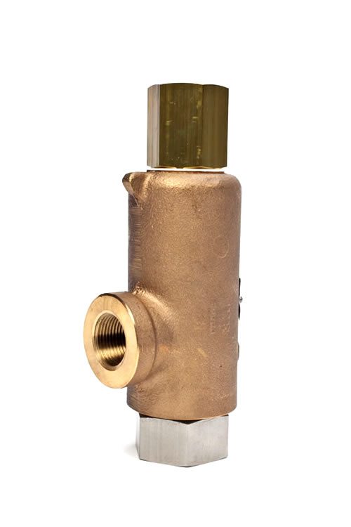
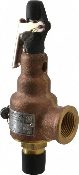
4 Bronze Safety ValVeS for air, GaS and Steam SerVice Model: Models 1 and 2 Compact assembly allows minimum space requirements. Precision lapped, metal-to-metal beveled seat provides premium shutoff. Adjustable blowdown for precise opening, with minimum preopen or simmer, and exact blowdown control. Available in top or side outlet. Nickel plating for use on institutional equipment and vibration dampener on lift lever both available. 1/2", 3 /4" and 1" [15, 18 and 25 mm] 250 psig [17.2 barg]/406 F [208 C] Air and non-hazardous gas service. Air/Gas compressors - portable or stationary. Pressure vessels - including tanks, receivers, intercoolers, aftercoolers. Steam turbines, kettles, other steam-processing equipment. Request KUKMC-0375-US Bronze relief ValVeS for liquid SerVice Model: Models 19, 20 and 200 Extra heavy, rugged construction. Both inlet and outlet connections are cast integral with body to permit easy inspection and servicing without disconnecting piping. Seats lapped for optimum performance. Spherical pivot between disc and spring corrects misalignment and compensates for spring side thrust. 1/2" to 3" [15 to 80 mm] 500 psig [20.7 barg]/406 F [208 C] Overpressure relief and protection of pumps, tanks,lines and hydraulic systems. Pressure regulation. Continuous bypass relief. Request KUKMC-0376-US BraSS Safety relief ValVe for air and GaS SerVice Model: Model 30 Top-guided disc provides optimum performance. 1/4" [7 mm] 4000 psig [276 barg]/300 F [150 C] Small to medium size, multi-stage, air compressors, intercoolers, aftercoolers, instrument/control air lines and systems. Air tanks/receivers and pressurized equipment. Request KUKMC-0377-US 4 I KUKMC-0328-US
5 Sentinel relief ValVeS for Steam SerVice Model: Models 40R and 40RL All parts are stainless steel. Precision lapped beveled seats for optimum performance. Pivot between spring and disc corrects misalignment and compensates for spring side thrust. 1/2" and 3 /4" [15 and 18 mm] 400 psig [27.6 barg]/850 F [455 C] Sentinel (warning) on steam equipment. Intended as audible warning device, not for pressure relief. Steam turbines. Request KUKMC-0378-US iron, Steel, StainleSS Steel relief ValVeS for liquid SerVice Model: Models 71S and 171 Extra heavy, rugged construction. Seats lapped for optimum performance. Spherical pivot between disc and spring corrects misalignment and compensates for spring side thrust. 1/2" to 2" [15 to 50 mm] 400 psig [27.6 barg]/550 F [288 C] Overpressure relief and protection of pumps, tanks, lines and hydraulic systems. Acid, caustic, ammonia and other corrosive liquids requiring iron, steel or stainless steel materials. Pressure regulation. Bypass relief. All 316 stainless steel Models 171S suitable for sanitary/edible corrosive applications. Request KUKMC-0379-US iron relief ValVeS for liquid SerVice Model: Model 91 Extra heavy, rugged construction with bolted bonnet to permit easy inspection and servicing without removal from system. Quality cast iron body and bonnet with bronze trim (insert and disc). Available with optional stainless steel insert and disc. Spring is steel with aluminum painting for corrosion protection. High lift, wing guided disc offers high relieving capacity. Insert and disc lapped for optimum performance. Pivot between disc and spring corrects misalignment and compensates for side thrust. 1 1 /2" to 6" [40 to 150 mm] 400 psig [27.6 barg]/406 F [208 C] Overpressure relief and protection of pumps, tanks, lines and hydraulic systems. Pressure regulation. Suitable for installations where back pressures to 60 psig [4.14 barg] are present. Request KUKMC-0380-US KUKMC-0328-US I 5
6 iron relief ValVeS for liquid SerVice Model: Models 218 and 228 Extra heavy, rugged construction with bolted bonnet to permit easy inspection and servicing without removal from system. Quality cast iron body and bonnet with bronze trim (insert and disc). Available with optional stainless steel insert and disc. Spring is steel with aluminum painting for corrosion protection. High lift, wing guided disc offers high relieving capacity. Insert and disc lapped for optimum performance. Pivot between disc and spring corrects misalignment and compensates for side thrust. 3", 4" and 6" [80, 100 and 150 mm] Adjustable 60/200 psig [4.14/13.8 barg]/406 F [208 C] Fire Pump Service, UL and FM approved. 218 standard with handwheel for easy adjustment. Request KUKMC-0380-US StainleSS Steel relief ValVeS for liquid SerVice Model: Model 140 Compact design requires minimum installation space. Angle lapped seat provides tight shut-off. 3/8" and 1 /2" [10 and 15 mm] 300 psig [20.7 barg]/406 F [208 C] A general utility valve of all stainless steel construction, including spring, for liquid and non-code vapor installations. Request KUKMC-0381-US Safety ValVeS for air GaS, cryogenic SerVice Model: Models 189, 363 and 389 Unique three-piece disc assembly (with Teflon seat/seal) offers superior leak-free performance over the entire pressure/temperature operating range. Control ring offers precise adjustment of blowdown. Heavy duty construction provides long service life. Pivot between disc and spring corrects for all misalignment and compensates for spring side thrust. 1/2" and 3 /4" [15 and 18 mm] 2500 psig [172.4 barg]/350 F [177 C] Cryogenic cold and liquefied gas, oxygen and gas service. Multi-stage air and gas compressors, intercoolers and aftercoolers and receivers. Thermal expansion relief and/or full rated capacity discharge. Air, gas and liquefied gas lines and systems. Request KUKMC-0382-US 6 I KUKMC-0328-US
7 iron Vacuum ValVeS Model: Vacuum Limits: Model 215V High capacity full nozzle design. Bronze nozzle, disc and guide with cast iron housing. Flat bronze valve seats are lapped for optimum performance. Warn ring offers easy adjustability for precise opening and minimum pre-open or simmer and exact blowdown control. Pivot between disc and spring corrects misalignment and compensates for spring side thrust. 2", 2 1 /2" and 3" [50, 65 and 80 mm] 2" to 29" Hg [67.7 to 982 mbarg]/406 F [208 C] Bulk hauling trailers/equipment. Light gauge tanks. Protection of high volume vacuum pumps and conveying systems. Request KUKMC-0383-US iron Safety ValVeS for air and non-hazardous GaS SerVice Model: Model 337 High capacity full nozzle design. Bronze nozzle, disc and guide with cast iron housing. Flat bronze valve seats are lapped for optimum performance. Warn ring offers easy adjustability for precise opening and minimum pre-open or simmer and exact blow-down control. Pivot between disc and spring corrects misalignment and compensates for spring side thrust. Reversible lift lever for pull-up or pull-down manual testing. Optional SS trim available. 2", 2 1 /2" and 3" [50, 65 and 80 mm] 60 psig [4.14 barg]/406 F [208 C] Protection of low-to-medium pressure, high volume blowers, compressors and pneumatic conveying systems. Bulk hauling trailers/equipment. Light gauge trucks. Blower relief ValVeS Request KUKMC-0383-US Model: Model 338 A non-code modulating relief valve for air service. 2" [50 mm] 5 to 30 psig [0.69 to 2.06 barg] -30 F to 400 F [-34 C to 204 C] Protection of low to medium pressure, high volume blowers. Bulk hauling trailers/equipment. Request KUKMC-0258-US KUKMC-0328-US I 7
8 relief ValVeS for air/gas SerVice Model: Models 230, 330, 330S and 333S Lightweight aluminum construction, resistant to environmental and internal corrosion. Opening pressure is repetitively consistent, relief action is smooth, reseating is positive with minimum pressure drop. The full spring load is never imparted to synthetic disc insert. Seat tightness increases to a maximum as inlet pressure approaches the opening pressure. Urethane soft seat available for improved seating performance. 1/4" to 1 /2" [7 to 15 mm] 330: 1000 psig [69.9 barg] minimum, 5500 psig [379.2 barg] maximum/ 185 F [85 C] 330S/333S: 1000 psig [69.9 barg] minimum, 6500 psig [448.1 barg] maximum/ 185 F [85 C] 230: 300 psig [20.7 barg] minimum, 1500 psig [103.4 barg] maximum/ 185 F [85 C] Multi-stage high pressure compressors, intercoolers and after-coolers. High pressure receivers and storage bottles. Thermal expansion relief. Breathing air pac recharge compressors. Scuba recharge compressors. Request KUKMC-0384-US Steel, StainleSS Steel Safety/relief ValVeS for liquid, air, GaS, Steam SerVice Model: Models 264, 265, 266, and 267 Extra heavy rugged construction. Top guided design offers high capacity with in 2 [ cm 2 ] orifice area. Seats lapped to optical flatness. Ball bearing pivot between disc and spring corrects misalignment and compensates for spring side thrust. O-ring soft seat available. 1/2", 3 /4" and 1" [15, 18, and 25 mm] 3300 psig [227.6 barg]/750 F [400 C] Protection of pumps, compressors, pressure vessels or systems handling corrosive liquids or vapors at high pressure and/or temperature. Sentinel (warning) on steam equipment. Request KUKMC-0385-US 8 I KUKMC-0328-US
9 Steel Safety ValVeS for Steam, air, non-hazardous GaS SerVice Model: Models 300 and 600 drip pan elbow Heavy duty construction of high quality steel with stainless steel full-nozzle trim. Bolted bonnet design for easy maintenance. Steel yoke incorporates a cover-shield for guiding surfaces and provides for fully exposed spring. Seats lapped to optical flatness. Dual control rings offer easy adjustability for precision opening with minimum pre-open or simmer and exact blowdown control. Heavy duty lift lever assembly. 1 1 /4" to 6" [32 through 150 mm] 1000 psig [69 barg]/750 F [ 400 C] Steam boilers and generators. Pressure reducing stations. Air/gas compressors reciprocating or rotary. Pressure vessels including tanks, receivers, intercoolers, oil-gas separators, lines. Gags available. Request KUKMC-0387-US Model: Model 299 Illustration shows a discharge elbow and drip pan unit attached to a safety valve with female NPT outlet. For safety valves with flanged outlets 2" to 4" use companion flange, short nipple and drip pan elbow, all same size as valve outlet. 6" and 8" elbows have integral 125# ANSI B16.1 Flange. Important - Length of discharge piping must be kept to a minimum. For design considerations see articles: Steam Flow Through Safety Valve Vent Pipes by H.E. Brandmaier and M.E. Knebel (Dec. 1975) and Analysis of Power Plant Safety and Relief Valve Vent Stacks by G.S. Liao (Nov. 1974) available through ASME Publications. Recommended installation on outlet/discharge pipe for safety valves. Used on steam service. Request KUKMC-0386-US KUKMC-0328-US I 9
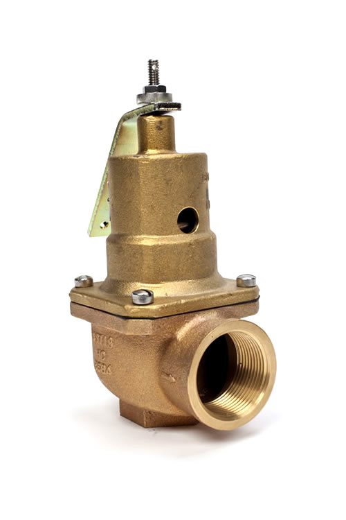
10 Safety ValVeS for Hot water HeatinG BoilerS Model: Model 537 Extra heavy construction provides long life. Top guided disc assembly incorporates resilient seal in seating area. Working parts are protected from corrosion by discharged liquid by an isolating diaphragm. Pivot between disc assembly and stem corrects for misalignment and compensates for spring side thrust. Heavy duty lift lever. 3/4" to 2" [18 to 50 mm] 160 psig [11 barg]/250 F [121 C] Hot water boiler and generators. ASME Code Section IV. Request KUKMC-0388-US Brass Safety Valves for Air, Non-hazardous Gas Model: Models 541, 542 and 548 Top guided disc High capacity Brass construction Manual lift ring Canadian registered. 541 Brass construction/buna-n seat 542 Brass construction/viton seat 548 Brass construction/ss seat (metal seats) 1/4" and 1 /2" [7 and 15 mm] 400 psig [27.6 barg]/400 F [204 C] Small-to-medium size, single and multi-stage, air compressors, intercoolers, aftercoolers, instrument/control air lines and systems. Air tanks/receivers and pressurized equipment. Request KUKMC-0389-US StainleSS Steel Safety ValVeS for air and GaS SerVice Model: Models 803 and 818 Lightweight aluminum and SS construction, resistant to environmental and internal corrosion. 1/4" and 2" [7 and 50 mm] 803: 6000 psig [413.8 barg]/185 F [85 C] 818: 150 psig [10.3 barg]/300 F [150 C] Small to medium size, single and multi-stage, air compressors, intercoolers, aftercoolers, instrument/control air lines and systems. Air tanks/receivers and pressurized equipment. Request KUKMC-0390-US 10 I KUKMC-0328-US
11 Bronze, Steel and StainleSS Steel Safety relief ValVeS for air, GaS, Steam, liquid and Vacuum SerVice Model: Models 910, 911, 912 and 913 Valve housing is heavy duty cast steel, stainless steel or bronze. Standard spring material is stainless steel suitable for temperatures to 550 F [288 C]. High temperature alloy spring good to 800 F [427 C]. Hex on valve nozzle provides for easy installation. Single control ring offers easy adjustability of blowdown. Pivoting disc design offers exceptional seat alignment. Seats lapped to optical flatness. Guide-to-nozzle ratio reduces friction. Models 920, 921 and 927 are certified for ASME Section I - Special Requirements. Models 916, 917, 918 and 919 O-ring soft seated valves are temperature limited by soft seat material. Available for FM Firepump service. 1/2" to 2" [15 to 50 mm] 910: 1400 psig [96.5 barg]/800 F [427 C] steel/stainless steel trim, 911: 1400 psig [96.5 barg]/800 F [427 C] all stainless steel, 912: 300 psig [17.2 barg]/406 F [208 C] bronze/brass trim, 913: 1400 psig [96.5 barg]/425 F [219 C] bronze/sst trim Air/gas compressors. Liquid Filled Pressure Vessels/Systems ASME Sec. VIII (UV). High Temperature/Pressure Hot Water Boilers ASME Sec. I (V). Pressure vessels containing gas, air or steam. Process and industrial applications requiring steel/stainless steel construction. Optional resilient soft seats available for superior leak free performance. Vacuum service. Request KUKMC-0392-US KUKMC-0328-US I 11
12 iron Safety ValVeS for Steam HeatinG BoilerS Model: Model 930 Extra high capacity for industrial, commercial and residential low pressure, steam heating boilers. Cast iron with bronze nozzle, disc and guide. Large seat area/guide area ratio, along with disc pivot design insures top valve performance. Flat bronze valve seats are lapped for optimum performance. Reversible lift lever for pull-up or pull-down manual testing. 2", 2 1 /2" and 3" [50, 65 and 80 mm] 5 psig [1.03 barg]/250 F [122 C] Low pressure steam heating boilers ASME Code Section IV, 15# set pressure. Request KUKMC-0391-US Bronze Safety ValVeS for air Steam, non-hazardous GaS Model: Series 6000 Valve housing A heavy duty casting. Wide hex on valve body provides clearance for easy installation. Seats lapped to optical flatness. Dual control rings offer easy adjustability for precise opening with minimum pre-open or simmer and exact blowdown control. Ball bearing pivot between disc and spring corrects misalignment and compensates for spring side thrust. Grooved piston type disc reduces sliding area and friction. Heavy duty lift lever assembly. Models 6010, 6030, 6182 and 6130 provided with optional resilient O-ring seat for superior leak- free performance. Models 6021, 6121, 6221, and 6934 offer Teflon (PFA) disc insert for exceptional leak-free performance (use on steam only). Models 6030, 6130, 6230, and 6935 supplied with stainless steel disc and nozzle for use on severe applications and/or set pressure up to 300 psig [20.7 barg]. 1/2" to 2 1 /2" [15 to 65 mm] 300 psig [20.7 barg]/425 F [219 C] Steam boilers and generators. Air/gas compressors reciprocating or rotary portable or stationary, intercoolers and aftercoolers. Pressure Vessels containing steam, air or non-hazardous gas. Including tanks, receivers, sterilizers and autoclaves. Pressure Reducing Valves protection of the discharge or low pressure side of system. Models 6933, 6934 and 6935 are certified for ASME Section IV. O-ring disk available with BUNA-N, EPR and Viton. Request KUKMC-0394-US 12 I KUKMC-0328-US
13 iron Safety ValVeS for air Steam, non-hazardous GaS SerVice Model: Models 6252 and 6254 Heavy duty construction of high quality cast iron with stainless steel semi-nozzle trim. Bolted bonnet design for easy maintenance. Seats lapped to optical flatness. Dual control rings offer easy adjustability for precision opening with minimum pre-open or simmer and exact blowdown control. Heavy duty lift lever assembly. 1 1 /2" to 6" [40 to 150 mm] 250 psig [17.2 barg]/406 F [208 C] Steam boilers and generators. Pressure reducing stations. Air/gas compressors reciprocating or rotary. Pressure vessels including tanks, receivers, intercoolers, oil-gas separators, lines. Blower applications. Vacuum service. Request KUKMC-0393-US KUKMC-0328-US I 13
14 Model Index Model in Inlet Sizes [mm] NPT Flange Air/Gas Steam Hot Water Liquid Vacuum Model in Inlet Sizes [mm] NPT Flange Air/Gas Steam Hot Water Liquid Vacuum 1 and 2 1/2, 3/4-1 [15, 18-25] n n n 19 1/2-3 [15-80] n n n 20 1/2-3 [15-80] n n n 200A/200H 1/2-2 [15-50] n n n 30 1/4 [7] n n 40R 1/2-3/4 [15-18] n n 71S 1/2-2 [15-50] n n 171 1/2-2 [15-50] n n 171S 1/2-2 [15-50] n n 91 11/4-6 [32-150] n n n [80-150] n n n [80-150] n n n 140 3/8-1/2 [10-15] n n 189 1/2-3/4 [15-18] n n 363 1/2-3/4 [15-18] n n 389 1/2-3


 8613371530291