
live steam safety valve factory

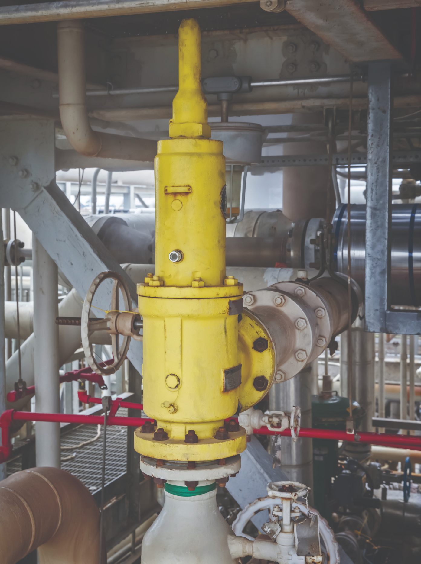
After a boiler has been engineered, built and tested for a given operating pressure there is only one reliable way to prevent operation of the boiler above this design pressure. This is a safety valve. The safety valve should be sized so that a single valve can handle the maximum steam production rate of the boiler and once open prevent boiler pressure to continue to rise. Standard operating procedure for the last century has been to install two safety valves on the boiler, one set 3-5 lbs below the design pressure and one valve set at the design pressure.
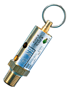
The 1st valve listed below is a true adjustable differential pop valve. The differential is adjured through the differential rings lock screw hole, from 3 PSI to whatever the operator desires. The pressure of the valve can be adjusted from 40 to 200 PSI.
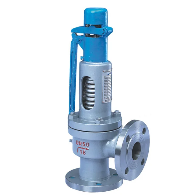
The other valves listed are adjustable for release pressure and have a "pop" action: The pressure differential is not adjustable on these valves. If the valves are operated above their nominal pressure, the set-reset differential increases. If operated at lower pressure, the differential decreases to the point of disappearing about 10-15% below nominal pressure.

... -start valve with Series MX2 air treatment units without the need for additional connection interfaces. The soft-start valve is positioned upstream of the safety valves, ...
Two hands safety valve, which allows a safety use of two hands pneumatic controls (for example two push-button 3/2 N.C. to a certain distance) excluding false signals in case of push-button ...
The SI2 safety valve prevents the allowed operating pressure from being exceeded by more than 10%. If, after opening, the adjusted response pressure falls ...
... stainless steel full-lift clean service safety valve designed to AD Merkblatt A2 and TRD 421 standards and suitable for pure steam, vapour and inert gases.
Insert style flow control valves are comprised of a precision orifice in parallel with a check valve, combined into a single component. Each is designed for easy installation into metal housings using ...
Press-in style flow control valves are comprised of a precision flow orifice in parallel with a check valve, combined into a single component. Each part is designed for easy installation into plastic ...
If you have been searching for a safety release valve that you can use to reduce short-term pressure surges successfully and diminish the effects of gas leaks, this is the product for you. With a pe of ...
... have been type tested as well. These pressure regulators have safety valves which will slam shut in the event of emergencies, such as the gas reaching too high a pressure level. The valve ...
This product has hydraulically actuated class A gas safety valves to EN 161 used for automatic shut-off. It shuts off when unstimulated for gas and air, or even biologically produced methane. It has AISi ...
The S 104 Safety Shut Off valve is mainly used to avoid any damage to components as well as to avoid too high or too low pressure in the gas train. This could cause high financial losses and/or injured ...
The S50 Safety Shut Off valve is mainly used to avoid any damage to components as well as to avoid too high or too low pressure in the gas train. This could cause high financial losses and/or injured ...
The S100 Safety Shut Off valve is mainly used to avoid any damage to components as well as to avoid too high or too low pressure in the gas train. This could cause high financial losses and/or injured ...
... Pressure Safety Valve + Rupture Disk is protected and may be utilized autonomously as essential security gadgets or in conjunction. There are 3 possible combinations. The first combinations ...
Excavator pipe-rupture valves prevent uncontrolled cylinder movement in the event that a pipe or hose bursts. The ESV valve fulfills all of the requirements of the ISO 8643 and EN 474-5 standards for ...
Material: Body- CF8M; Valve Seat- CF8M Métal Seat, PTFE Soft Seat available Orifice Size: fc"(15mm), 3/4M(20mm), l"(25mm), l1/4,’(32mm)I ltë”(40mm), ...
The Safety valves from ATOS are designed to guarantee protection for application on various devices, especially those that monitor spool position. They are also recommended for hydraulic ...

300LPM01-L is a safety relief valve for steam service on unfired pressure vessels. It is also used on Pressure Reducing Stations, Accumulators, Cleaners, and Distillers. Meets ASME code, Section VIII.
Model 300LPM01-K is a safety relief valve for air, gas and vapors. It is used on compressors, receivers, burners, dryers and other piping systems. Meets ASME code, Section VIII.

Taylor Valve Technology® is a manufacturer leader in high-quality industrial valves. We deliver safety relief, high-pressure relief, and back pressure relief valves. Our wide array of choke and control valves and pilot-operated valve products are second to none. Products are designed for demanding industrial needs, meeting quality API and ASME Code requirements. High-demand oil & gas industry, chemical plants, power generators, and the processing industry depend on our valves for consistency and durability. Get effective flow control of liquid, steam, and gas. Valves ship from the Taylor Valve Technology, Inc. United States facility. Delivering worldwide, you can depend on quick turnaround times.
Kunkle Relief Valve OverviewWhen it comes to industrial and commercial safety and relief valve products, Kunkle’s valve’s catalog is second to none in steam, air, gas, and liquid applications.
Kunkle relief valves range in size from ¼” NPT to 6” flange and are suitable in cryogenic and high temperatures up to 800°F environments at vacuum to 7,500 psig pressure. Kunkle Valve’s code certifications meet several global and national board standards, including ASME Section I, Section IV, and Section VIII, PED, CRN, TU and Chinese, as well as non-code requirements.
Relief Valves for Steam ServiceSteam supplies heat for industrial and chemical processes and also is used to heat buildings, supply mechanical energy, and drive mechanical equipment. Steam moves from the boiler to the end point, then heats by direct heating or indirect heating through a heat exchanger. Kunkle steam relief valves are critical to protecting equipment such as boilers, steam lines, and pressure valves, from being over-pressurized.
Relief Valves for Air ServiceKunkle designs valves for air service, for example for air compressors in mechanical shops and small factories where either low-pressure or high-pressure air is required. NASVI stocks Kunkle relief valves for air service in iron, steel and bronze for a variety of uses.
Relief Valves for Liquid ServiceKunkle also makes valves for liquid service, which provide bypass relief in a variety of applications and liquid types.
More About KunkleKunkle Valve is a renowned pressure relief valve manufacturer. Erastus B. Kunkle invented the safety valve to prevent overpressure in locomotive engines. Kunkle patented it in 1875. Since that time, Kunkle has earned its reputation for high-quality valves, and other equipment manufacturers ship their products with Kunkle’s valves pre-installed.
NASVI has stocked Kunkle safety relief valves since we opened in 1975, so we are confident when we call ourselves Kunkle safety valve experts. Every day we fulfill orders for our customers looking for Kunkle relief valves for steam, air, gas, and liquid applications.

Industry leading pressure and safety relief valve designs with over 140 years of technical and application expertise providing custom engineered solutions for O&G, Refining, Chemical, Petrochemical, Process and Power applications. Our designs meet global and local codes and standards (API 526; ASME Section I, IV & VIII; EN ISO 4126; PED & more). Gain insight into the performance of your pressure relief valves with wireless monitoring.

ASME Section IV Safety Relief Valve for protection of small hot water heating boilers and hydronic heating systems. Made from proven ASTM grade Brass and Bronze materials with decorative chrome finish.
ASME Section IV capacity certified bronze safety relief valve for protection of hot water heating boilers, systems and similar equipment. It can be Pre-set to any pressure ranging between 20 to 80 psig (1.4 to 5.5 bar) at 250�F (121�C) max
ASME Section IV capacity certified bronze safety relief valve for protection of hot water heating boilers, systems and similar equipment. It can be pre-set to any pressure ranging from 15 to 160 psig (1 to 11 bar) at 250�F (121�C) max.
ASME Section VIII design certified Safety Valve to protect portable steam vessel applications such as autoclaves, sterilizers and pressure cookers against excess pressure build-up. Made from proven ASTMgrade Brass with optional decorative chrome finish.
ASME Section I & VIII air and steam capacity certified safety valve for overpressure protection of steam power boilers, deaerators, accumulators, pressure reducing stations and pressure piping systems.
Medium capacity safety valves protect ASME Section IV low pressure steam heatingboilers. Cast bronze, full nozzle design features PTFE faced elastomer soft seatingfor dependable operation.
The Apollo� 13 Series bronze low pressure steam safety valve is designed to meet ASME Section IV code requirements for protection of steam heating boilers, systems and similar equipment.
The Apollo� 13 Series bronze low pressure steam safety valve is designed to meet ASME Section IV code requirements for protection of steam heating boilers, systems and similar equipment.
The Apollo� 14 Series is a 100% American Made Bronze Safety Relief Valve for protection of steam boilers, low pressure, high volume blowers, compressors and vacuum systems.
ASME Section I and VIII capacity certified safety valve for overpressure protection of steam power boilers, systems, pressure vessels, piping and similar equipment. Suitable for steam, air and non-hazardous gases.
ASME Section I/Section VIII capacity certified safety valve for overpressure protection of steam power boilers, steam and air systems, pressure vessels, piping and similar equipment. Compact and economic design ideal for OEM applications.
ASME Section VIII capacity certified safety relief valve for overpressure protection of steam, air/gas and liquid systems, pressure vessels, piping and similar equipment.
Drip Pan Elbows connect to the safety valveoutlet and direct steam discharge into the discharge piping, allowing condensate to drain away. Isolates the valve from piping stresses.Highly recommended in steam service.
ASME Section I & VIII air and steam capacity certified safety valve for overpressure protection of steam power boilers, deaerators, accumulators, pressure reducing stations and pressure piping systems.
High volume air relief valves designed for low pressure air and gas service. Ruggedbronze construction features elastomer soft seating and TFE coated discs fordependable operation.
ASME Section VIII capacity certified relief valve foroverpressure protection of compressors, intercoolers,dryers, receivers, control and instrument air lines andsimilar equipment.
ASME Section I and VIII capacity certified safety valve for overpressure protection of steam power boilers, systems, pressure vessels, piping and similar equipment. Suitable for steam, air and non-hazardous gases.
ASME Section I/Section VIII capacity certified safety valve for overpressure protection of steam power boilers, steam and air systems, pressure vessels, piping and similar equipment. Compact and economic design ideal for OEM applications.
ASME Section VIII capacity certified safety relief valve for overpressure protection of steam, air/gas and liquid systems, pressure vessels, piping and similar equipment.
High flow vacuum relief valves feature one piece cast bronze bodies, Teflon coated discs and elastomer soft seating provide accurate and dependable operation. Ideal for use with high volume vacuum systems, bulk hauling tanks and trailers, powdered solids/bulk handling and pneumatic conveying equipment.
The Apollo� Model VR Vacuum Relief valve is designed to automatically vent a system should avacuum occur. It prevents siphoning of water from the system and/or tank collapse.
There is a wide range of safety valves available to meet the many different applications and performance criteria demanded by different industries. Furthermore, national standards define many varying types of safety valve.
The ASME standard I and ASME standard VIII for boiler and pressure vessel applications and the ASME/ANSI PTC 25.3 standard for safety valves and relief valves provide the following definition. These standards set performance characteristics as well as defining the different types of safety valves that are used:
ASME I valve - A safety relief valve conforming to the requirements of Section I of the ASME pressure vessel code for boiler applications which will open within 3% overpressure and close within 4%. It will usually feature two blowdown rings, and is identified by a National Board ‘V’ stamp.
ASME VIII valve- A safety relief valve conforming to the requirements of Section VIII of the ASME pressure vessel code for pressure vessel applications which will open within 10% overpressure and close within 7%. Identified by a National Board ‘UV’ stamp.
Full bore safety valve - A safety valve having no protrusions in the bore, and wherein the valve lifts to an extent sufficient for the minimum area at any section, at or below the seat, to become the controlling orifice.
Conventional safety relief valve -The spring housing is vented to the discharge side, hence operational characteristics are directly affected by changes in the backpressure to the valve.
Balanced safety relief valve -A balanced valve incorporates a means of minimising the effect of backpressure on the operational characteristics of the valve.
Pilot operated pressure relief valve -The major relieving device is combined with, and is controlled by, a self-actuated auxiliary pressure relief device.
Power-actuated safety relief valve - A pressure relief valve in which the major pressure relieving device is combined with, and controlled by, a device requiring an external source of energy.
Standard safety valve - A valve which, following opening, reaches the degree of lift necessary for the mass flowrate to be discharged within a pressure rise of not more than 10%. (The valve is characterised by a pop type action and is sometimes known as high lift).
Full lift (Vollhub) safety valve -A safety valve which, after commencement of lift, opens rapidly within a 5% pressure rise up to the full lift as limited by the design. The amount of lift up to the rapid opening (proportional range) shall not be more than 20%.
Direct loaded safety valve -A safety valve in which the opening force underneath the valve disc is opposed by a closing force such as a spring or a weight.
Proportional safety valve - A safety valve which opens more or less steadily in relation to the increase in pressure. Sudden opening within a 10% lift range will not occur without pressure increase. Following opening within a pressure of not more than 10%, these safety valves achieve the lift necessary for the mass flow to be discharged.
Diaphragm safety valve -A direct loaded safety valve wherein linear moving and rotating elements and springs are protected against the effects of the fluid by a diaphragm
Bellows safety valve - A direct loaded safety valve wherein sliding and (partially or fully) rotating elements and springs are protected against the effects of the fluids by a bellows. The bellows may be of such a design that it compensates for influences of backpressure.
Controlled safety valve - Consists of a main valve and a control device. It also includes direct acting safety valves with supplementary loading in which, until the set pressure is reached, an additional force increases the closing force.
Safety valve - A safety valve which automatically, without the assistance of any energy other than that of the fluid concerned, discharges a quantity of the fluid so as to prevent a predetermined safe pressure being exceeded, and which is designed to re-close and prevent further flow of fluid after normal pressure conditions of service have been restored. Note; the valve can be characterised either by pop action (rapid opening) or by opening in proportion (not necessarily linear) to the increase in pressure over the set pressure.
Direct loaded safety valve -A safety valve in which the loading due to the fluid pressure underneath the valve disc is opposed only by a direct mechanical loading device such as a weight, lever and weight, or a spring.
Assisted safety valve -A safety valve which by means of a powered assistance mechanism, may additionally be lifted at a pressure lower than the set pressure and will, even in the event of a failure of the assistance mechanism, comply with all the requirements for safety valves given in the standard.
Supplementary loaded safety valve - A safety valve that has, until the pressure at the inlet to the safety valve reaches the set pressure, an additional force, which increases the sealing force.
Note; this additional force (supplementary load), which may be provided by means of an extraneous power source, is reliably released when the pressure at the inlet of the safety valve reaches the set pressure. The amount of supplementary loading is so arranged that if such supplementary loading is not released, the safety valve will attain its certified discharge capacity at a pressure not greater than 1.1 times the maximum allowable pressure of the equipment to be protected.
Pilot operated safety valve -A safety valve, the operation of which is initiated and controlled by the fluid discharged from a pilot valve, which is itself, a direct loaded safety valve subject to the requirement of the standard.
The common characteristic shared between the definitions of conventional safety valves in the different standards, is that their operational characteristics are affected by any backpressure in the discharge system. It is important to note that the total backpressure is generated from two components; superimposed backpressure and the built-up backpressure:
Subsequently, in a conventional safety valve, only the superimposed backpressure will affect the opening characteristic and set value, but the combined backpressure will alter the blowdown characteristic and re-seat value.
The ASME/ANSI standard makes the further classification that conventional valves have a spring housing that is vented to the discharge side of the valve. If the spring housing is vented to the atmosphere, any superimposed backpressure will still affect the operational characteristics. Thiscan be seen from Figure 9.2.1, which shows schematic diagrams of valves whose spring housings are vented to the discharge side of the valve and to the atmosphere.
By considering the forces acting on the disc (with area AD), it can be seen that the required opening force (equivalent to the product of inlet pressure (PV) and the nozzle area (AN)) is the sum of the spring force (FS) and the force due to the backpressure (PB) acting on the top and bottom of the disc. In the case of a spring housing vented to the discharge side of the valve (an ASME conventional safety relief valve, see Figure 9.2.1 (a)), the required opening force is:
In both cases, if a significant superimposed backpressure exists, its effects on the set pressure need to be considered when designing a safety valve system.
Once the valve starts to open, the effects of built-up backpressure also have to be taken into account. For a conventional safety valve with the spring housing vented to the discharge side of the valve, see Figure 9.2.1 (a), the effect of built-up backpressure can be determined by considering Equation 9.2.1 and by noting that once the valve starts to open, the inlet pressure is the sum of the set pressure, PS, and the overpressure, PO.
Balanced safety valves are those that incorporate a means of eliminating the effects of backpressure. There are two basic designs that can be used to achieve this:
Although there are several variations of the piston valve, they generally consist of a piston type disc whose movement is constrained by a vented guide. The area of the top face of the piston, AP, and the nozzle seat area, AN, are designed to be equal. This means that the effective area of both the top and bottom surfaces of the disc exposed to the backpressure are equal, and therefore any additional forces are balanced. In addition, the spring bonnet is vented such that the top face of the piston is subjected to atmospheric pressure, as shown in Figure 9.2.2.
The bellows arrangement prevents backpressure acting on the upper side of the disc within the area of the bellows. The disc area extending beyond the bellows and the opposing disc area are equal, and so the forces acting on the disc are balanced, and the backpressure has little effect on the valve opening pressure.
Bellows failure is an important concern when using a bellows balanced safety valve, as this may affect the set pressure and capacity of the valve. It is important, therefore, that there is some mechanism for detecting any uncharacteristic fluid flow through the bellows vents. In addition, some bellows balanced safety valves include an auxiliary piston that is used to overcome the effects of backpressure in the case of bellows failure. This type of safety valve is usually only used on critical applications in the oil and petrochemical industries.
Since balanced pressure relief valves are typically more expensive than their unbalanced counterparts, they are commonly only used where high pressure manifolds are unavoidable, or in critical applications where a very precise set pressure or blowdown is required.
This type of safety valve uses the flowing medium itself, through a pilot valve, to apply the closing force on the safety valve disc. The pilot valve is itself a small safety valve.
The diaphragm type is typically only available for low pressure applications and it produces a proportional type action, characteristic of relief valves used in liquid systems. They are therefore of little use in steam systems, consequently, they will not be considered in this text.
The piston type valve consists of a main valve, which uses a piston shaped closing device (or obturator), and an external pilot valve. Figure 9.2.4 shows a diagram of a typical piston type, pilot operated safety valve.
The piston and seating arrangement incorporated in the main valve is designed so that the bottom area of the piston, exposed to the inlet fluid, is less than the area of the top of the piston. As both ends of the piston are exposed to the fluid at the same pressure, this means that under normal system operating conditions, the closing force, resulting from the larger top area, is greater than the inlet force. The resultant downward force therefore holds the piston firmly on its seat.
If the inlet pressure were to rise, the net closing force on the piston also increases, ensuring that a tight shut-off is continually maintained. However, when the inlet pressure reaches the set pressure, the pilot valve will pop open to release the fluid pressure above the piston. With much less fluid pressure acting on the upper surface of the piston, the inlet pressure generates a net upwards force and the piston will leave its seat. This causes the main valve to pop open, allowing the process fluid to be discharged.
When the inlet pressure has been sufficiently reduced, the pilot valve will reclose, preventing the further release of fluid from the top of the piston, thereby re-establishing the net downward force, and causing the piston to reseat.
Pilot operated safety valves offer good overpressure and blowdown performance (a blowdown of 2% is attainable). For this reason, they are used where a narrow margin is required between the set pressure and the system operating pressure. Pilot operated valves are also available in much larger sizes, making them the preferred type of safety valve for larger capacities.
One of the main concerns with pilot operated safety valves is that the small bore, pilot connecting pipes are susceptible to blockage by foreign matter, or due to the collection of condensate in these pipes. This can lead to the failure of the valve, either in the open or closed position, depending on where the blockage occurs.
The terms full lift, high lift and low lift refer to the amount of travel the disc undergoes as it moves from its closed position to the position required to produce the certified discharge capacity, and how this affects the discharge capacity of the valve.
A full lift safety valve is one in which the disc lifts sufficiently, so that the curtain area no longer influences the discharge area. The discharge area, and therefore the capacity of the valve are subsequently determined by the bore area. This occurs when the disc lifts a distance of at least a quarter of the bore diameter. A full lift conventional safety valve is often the best choice for general steam applications.
The disc of a high lift safety valve lifts a distance of at least 1/12th of the bore diameter. This means that the curtain area, and ultimately the position of the disc, determines the discharge area. The discharge capacities of high lift valves tend to be significantly lower than those of full lift valves, and for a given discharge capacity, it is usually possible to select a full lift valve that has a nominal size several times smaller than a corresponding high lift valve, which usually incurs cost advantages.Furthermore, high lift valves tend to be used on compressible fluids where their action is more proportional.
In low lift valves, the disc only lifts a distance of 1/24th of the bore diameter. The discharge area is determined entirely by the position of the disc, and since the disc only lifts a small amount, the capacities tend to be much lower than those of full or high lift valves.
Except when safety valves are discharging, the only parts that are wetted by the process fluid are the inlet tract (nozzle) and the disc. Since safety valves operate infrequently under normal conditions, all other components can be manufactured from standard materials for most applications. There are however several exceptions, in which case, special materials have to be used, these include:
Cast steel -Commonly used on higher pressure valves (up to 40 bar g). Process type valves are usually made from a cast steel body with an austenitic full nozzle type construction.
For all safety valves, it is important that moving parts, particularly the spindle and guides are made from materials that will not easily degrade or corrode. As seats and discs are constantly in contact with the process fluid, they must be able to resist the effects of erosion and corrosion.
The spring is a critical element of the safety valve and must provide reliable performance within the required parameters. Standard safety valves will typically use carbon steel for moderate temperatures. Tungsten steel is used for higher temperature, non-corrosive applications, and stainless steel is used for corrosive or clean steam duty. For sour gas and high temperature applications, often special materials such as monel, hastelloy and ‘inconel’ are used.
A key option is the type of seating material used. Metal-to-metal seats, commonly made from stainless steel, are normally used for high temperature applications such as steam. Alternatively, resilient discs can be fixed to either or both of the seating surfaces where tighter shut-off is required, typically for gas or liquid applications. These inserts can be made from a number of different materials, but Viton, nitrile or EPDM are the most common. Soft seal inserts are not generally recommended for steam use.
Standard safety valves are generally fitted with an easing lever, which enables the valve to be lifted manually in order to ensure that it is operational at pressures in excess of 75% of set pressure. This is usually done as part of routine safety checks, or during maintenance to prevent seizing. The fitting of a lever is usually a requirement of national standards and insurance companies for steam and hot water applications. For example, the ASME Boiler and Pressure Vessel Code states that pressure relief valves must be fitted with a lever if they are to be used on air, water over 60°C, and steam.
A standard or open lever is the simplest type of lever available. It is typically used on applications where a small amount of leakage of the fluid to the atmosphere is acceptable, such as on steam and air systems, (see Figure 9.2.5 (a)).
A test gag (Figure 9.2.7) may be used to prevent the valve from opening at the set pressure during hydraulic testing when commissioning a system. Once tested, the gag screw is removed and replaced with a short blanking plug before the valve is placed in service.
The amount of fluid depends on the particular design of safety valve. If emission of this fluid into the atmosphere is acceptable, the spring housing may be vented to the atmosphere – an open bonnet. This is usually advantageous when the safety valve is used on high temperature fluids or for boiler applications as, otherwise, high temperatures can relax the spring, altering the set pressure of the valve. However, using an open bonnet exposes the valve spring and internals to environmental conditions, which can lead to damage and corrosion of the spring.
When the fluid must be completely contained by the safety valve (and the discharge system), it is necessary to use a closed bonnet, which is not vented to the atmosphere. This type of spring enclosure is almost universally used for small screwed valves and, it is becoming increasingly common on many valve ranges since, particularly on steam, discharge of the fluid could be hazardous to personnel.
Some safety valves, most commonly those used for water applications, incorporate a flexible diaphragm or bellows to isolate the safety valve spring and upper chamber from the process fluid, (see Figure 9.2.9).
In order to ensure that the maximum allowable accumulation pressure of any system or apparatus protected by a safety valve is never exceeded, careful consideration of the safety valve’s position in the system has to be made. As there is such a wide range of applications, there is no absolute rule as to where the valve should be positioned and therefore, every application needs to be treated separately.
A common steam application for a safety valve is to protect process equipment supplied from a pressure reducing station. Two possible arrangements are shown in Figure 9.3.3.
The safety valve can be fitted within the pressure reducing station itself, that is, before the downstream stop valve, as in Figure 9.3.3 (a), or further downstream, nearer the apparatus as in Figure 9.3.3 (b). Fitting the safety valve before the downstream stop valve has the following advantages:
• The safety valve can be tested in-line by shutting down the downstream stop valve without the chance of downstream apparatus being over pressurised, should the safety valve fail under test.
• When setting the PRV under no-load conditions, the operation of the safety valve can be observed, as this condition is most likely to cause ‘simmer’. If this should occur, the PRV pressure can be adjusted to below the safety valve reseat pressure.
Indeed, a separate safety valve may have to be fitted on the inlet to each downstream piece of apparatus, when the PRV supplies several such pieces of apparatus.
• If supplying one piece of apparatus, which has a MAWP pressure less than the PRV supply pressure, the apparatus must be fitted with a safety valve, preferably close-coupled to its steam inlet connection.
• If a PRV is supplying more than one apparatus and the MAWP of any item is less than the PRV supply pressure, either the PRV station must be fitted with a safety valve set at the lowest possible MAWP of the connected apparatus, or each item of affected apparatus must be fitted with a safety valve.
• The safety valve must be located so that the pressure cannot accumulate in the apparatus viaanother route, for example, from a separate steam line or a bypass line.
It could be argued that every installation deserves special consideration when it comes to safety, but the following applications and situations are a little unusual and worth considering:
• Fire - Any pressure vessel should be protected from overpressure in the event of fire. Although a safety valve mounted for operational protection may also offer protection under fire conditions,such cases require special consideration, which is beyond the scope of this text.
• Exothermic applications - These must be fitted with a safety valve close-coupled to the apparatus steam inlet or the body direct. No alternative applies.
• Safety valves used as warning devices - Sometimes, safety valves are fitted to systems as warning devices. They are not required to relieve fault loads but to warn of pressures increasing above normal working pressures for operational reasons only. In these instances, safety valves are set at the warning pressure and only need to be of minimum size. If there is any danger of systems fitted with such a safety valve exceeding their maximum allowable working pressure, they must be protected by additional safety valves in the usual way.
In order to illustrate the importance of the positioning of a safety valve, consider an automatic pump trap (see Block 14) used to remove condensate from a heating vessel. The automatic pump trap (APT), incorporates a mechanical type pump, which uses the motive force of steam to pump the condensate through the return system. The position of the safety valve will depend on the MAWP of the APT and its required motive inlet pressure.
This arrangement is suitable if the pump-trap motive pressure is less than 1.6 bar g (safety valve set pressure of 2 bar g less 0.3 bar blowdown and a 0.1 bar shut-off margin). Since the MAWP of both the APT and the vessel are greater than the safety valve set pressure, a single safety valve would provide suitable protection for the system.
Here, two separate PRV stations are used each with its own safety valve. If the APT internals failed and steam at 4 bar g passed through the APT and into the vessel, safety valve ‘A’ would relieve this pressure and protect the vessel. Safety valve ‘B’ would not lift as the pressure in the APT is still acceptable and below its set pressure.
It should be noted that safety valve ‘A’ is positioned on the downstream side of the temperature control valve; this is done for both safety and operational reasons:
Operation - There is less chance of safety valve ‘A’ simmering during operation in this position,as the pressure is typically lower after the control valve than before it.
Also, note that if the MAWP of the pump-trap were greater than the pressure upstream of PRV ‘A’, it would be permissible to omit safety valve ‘B’ from the system, but safety valve ‘A’ must be sized to take into account the total fault flow through PRV ‘B’ as well as through PRV ‘A’.
A pharmaceutical factory has twelve jacketed pans on the same production floor, all rated with the same MAWP. Where would the safety valve be positioned?
One solution would be to install a safety valve on the inlet to each pan (Figure 9.3.6). In this instance, each safety valve would have to be sized to pass the entire load, in case the PRV failed open whilst the other eleven pans were shut down.
If additional apparatus with a lower MAWP than the pans (for example, a shell and tube heat exchanger) were to be included in the system, it would be necessary to fit an additional safety valve. This safety valve would be set to an appropriate lower set pressure and sized to pass the fault flow through the temperature control valve (see Figure 9.3.8).
Note: these have simple adjustable spring loaded relief balls/surfaces that progressively release pressure when the setting is passed. They are not "pop"valves that trigger at a set pressure.

Consolidated boasts 140+ years of dedicated Pressure Relief Valve (PRV) Engineering and Manufacturing expertise. We know overpressure protection! With more than 10 major first-to-market products and features, Consolidated continues to deliver innovative technical solutions to the world"s most challenging overpressure protection applications. When combined with the expertise and full-scale service of the Green Tag Center (GTC) Network, Consolidated is able to provide a comprehensive approach to Valve Lifecycle Management (VLM) that is second to none.
Comprehensive Valve Lifecycle Management (VLM) enabled by state-of-the-art tools and delivered by the unparalleled Consolidated Green Tag Center (GTC) Network, Consolidated supports our product throughout the entire lifecycle.
Safety valves are an arrangement or mechanism to release a substance from the concerned system in the event of pressure or temperature exceeding a particular preset limit. The systems in the context may be boilers, steam boilers, pressure vessels or other related systems. As per the mechanical arrangement, this one get fitted into the bigger picture (part of the bigger arrangement) called as PSV or PRV that is pressure safety or pressure relief valves.
This type of safety mechanism was largely implemented to counter the problem of accidental explosion of steam boilers. Initiated in the working of a steam digester, there were many methodologies that were then accommodated during the phase of the industrial revolution. And since then this safety mechanism has come a long way and now accommodates various other aspects.
These aspects like applications, performance criteria, ranges, nation based standards (countries like United States, European Union, Japan, South Korea provide different standards) etc. manage to differentiate or categorize this safety valve segment. So, there can be many different ways in which these safety valves get differentiated but a common range of bifurcation is as follows:
The American Society of Mechanical Engineers (ASME) I tap is a type of safety valve which opens with respect to 3% and 4% of pressure (ASME code for pressure vessel applications) while ASME VIII valve opens at 10% over pressure and closes at 7%. Lift safety valves get further classified as low-lift and full lift. The flow control valves regulate the pressure or flow of a fluid whereas a balanced valve is used to minimize the effects induced by pressure on operating characteristics of the valve in context.
A power operated valve is a type of pressure relief valve is which an external power source is also used to relieve the pressure. A proportional-relief valve gets opened in a relatively stable manner as compared to increasing pressure. There are 2 types of direct-loaded safety valves, first being diaphragms and second: bellows. diaphragms are valves which spring for the protection of effects of the liquid membrane while bellows provide an arrangement where the parts of rotating elements and sources get protected from the effects of the liquid via bellows.
In a master valve, the operation and even the initiation is controlled by the fluid which gets discharged via a pilot valve. Now coming to the bigger picture, the pressure safety valves based segment gets classified as follows:
So all in all, pressure safety valves, pressure relief valves, relief valves, pilot-operated relief valves, low pressure safety valves, vacuum pressure safety valves etc. complete the range of safety measures in boilers and related devices.
Safety valves have different discharge capacities. These capacities are based on the geometrical area of the body seat upstream and downstream of the valve. Flow diameter is the minimum geometrical diameter upstream and downstream of the body seat.
The nominal size designation refers to the inlet orifice diameter. A safety Valve"s theoretical flowing capacity is the mass flow through an orifice with the same cross-sectional area as the valve"s flow area. This capacity does not account for the flow losses caused by the valve. The actual capacity is measured, and the certified flow capacity is the actual flow capacity reduced by 10%.
A safety valve"s discharge capacity is dependent on the set pressure and position in a system. Once the set pressure is calculated, the discharge capacity must be determined. Safety valves may be oversized or undersized depending on the flow throughput and/or the valve"s set pressure.
The actual discharge capacity of a safety valve depends on the type of discharge system used. In liquid service, safety valves are generally automatic and direct-pressure actuated.
A safety valve is used to protect against overpressure in a fluid system. Its design allows for a lift in the disc, indicating that the valve is about to open. When the inlet pressure rises above the set pressure, the guide moves to the open position, and media flows to the outlet via the pilot tube. Once the inlet pressure falls below the set pressure, the main valve closes and prevents overpressure. There are five criteria for selecting a safety valve.
The first and most basic requirement of a safety valve is its ability to safely control the flow of gas. Hence, the valve must be able to control the flow of gas and water. The valve should be able to withstand the high pressures of the system. This is because the gas or steam coming from the boiler will be condensed and fill the pipe. The steam will then wet the safety valve seat.
The other major requirement for safety valves is their ability to prevent pressure buildup. They prevent overpressure conditions by allowing liquid or gas to escape. Safety valves are used in many different applications. Gas and steam lines, for example, can prevent catastrophic damage to the plant. They are also known as safety relief valves. During an emergency, a safety valve will open automatically and discharge gas or liquid pressure from a pressurized system, preventing it from reaching dangerous levels.
The discharge capacity of a safety valve is based on its orifice area, set pressure, and position in the system. A safety valve"s discharge capacity should be calculated based on the maximum flow through its inlet and outlet orifice areas. Its nominal size is often determined by manufacturer specifications.
Its discharge capacity is the maximum flow through the valve that it can relieve, based on the maximum flow through each individual flow path or combined flow path. The discharge pressure of the safety valve should be more than the operating pressure of the system. As a thumb rule, the relief pressure should be 10% above the working pressure of the system.
It is important to choose the discharge capacity of a safety valve based on the inlet and output piping sizes. Ideally, the discharge capacity should be equal to or greater than the maximum output of the system. A safety valve should also be installed vertically and into a clean fitting. While installing a valve, it is important to use a proper wrench for installation. The discharge piping should slope downward to drain any condensate.
The discharge capacity of a safety valve is measured in a few different ways. The first is the test pressure. This gauge pressure is the pressure at which the valve opens, while the second is the pressure at which it re-closes. Both are measured in a test stand under controlled conditions. A safety valve with a test pressure of 10,000 psi is rated at 10,000 psi (as per ASME PTC25.3).
The discharge capacity of a safety valve should be large enough to dissipate a large volume of pressure. A small valve may be adequate for a smaller system, but a larger one could cause an explosion. In a large-scale manufacturing plant, safety valves are critical for the safety of personnel and equipment. Choosing the right valve size for a particular system is essential to its efficiency.
Before you use a safety valve, you need to know its discharge capacity. Here are some steps you need to follow to calculate the discharge capacity of a safety valve.
To check the discharge capacity of a safety valve, the safety valve should be installed in the appropriate location. Its inlet and outlet pipework should be thoroughly cleaned before installation. It is important to avoid excessive use of PTFE tape and to ensure that the installation is solid. The safety valve should not be exposed to vibration or undue stress. When mounting a safety valve, it should be installed vertically and with the test lever at the top. The inlet connection of the safety valve should be attached to the vessel or pipeline with the shortest length of pipe. It must not be interrupted by any isolation valve. The pressure loss at the inlet of a safety valve should not exceed 3% of the set pressure.
The sizing of a safety valve depends on the amount of fluid it is required to control. The rated discharge capacity is a function of the safety valve"s orifice area, set pressure, and position in the system. Using the manufacturer"s specifications for orifice area and nominal size of the valve, the capacity of a safety valve can be determined. The discharge flow can be calculated using the maximum flow through the valve or the combined flows of several paths. When sizing a safety valve, it"s necessary to consider both its theoretical and actual discharge capacity. Ideally, the discharge capacity will be equal to the minimum area.
To determine the correct set pressure for a safety valve, consider the following criteria. It must be less than the MAAP of the system. Set pressure of 5% greater than the MAAP will result in an overpressure of 10%. If the set pressure is higher than the MAAP, the safety valve will not close. The MAAP must never exceed the set pressure. A set pressure that is too high will result in a poor shutoff after discharge. Depending on the type of valve, a backpressure variation of 10% to 15% of the set pressure cannot be handled by a conventional valve.


 8613371530291