
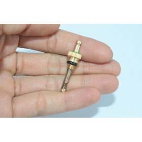
live steam safety valve free sample

After a boiler has been engineered, built and tested for a given operating pressure there is only one reliable way to prevent operation of the boiler above this design pressure. This is a safety valve. The safety valve should be sized so that a single valve can handle the maximum steam production rate of the boiler and once open prevent boiler pressure to continue to rise. Standard operating procedure for the last century has been to install two safety valves on the boiler, one set 3-5 lbs below the design pressure and one valve set at the design pressure.
The 1st valve listed below is a true adjustable differential pop valve. The differential is adjured through the differential rings lock screw hole, from 3 PSI to whatever the operator desires. The pressure of the valve can be adjusted from 40 to 200 PSI.
The other valves listed are adjustable for release pressure and have a "pop" action: The pressure differential is not adjustable on these valves. If the valves are operated above their nominal pressure, the set-reset differential increases. If operated at lower pressure, the differential decreases to the point of disappearing about 10-15% below nominal pressure.

In order to ensure that the maximum allowable accumulation pressure of any system or apparatus protected by a safety valve is never exceeded, careful consideration of the safety valve’s position in the system has to be made. As there is such a wide range of applications, there is no absolute rule as to where the valve should be positioned and therefore, every application needs to be treated separately.
A common steam application for a safety valve is to protect process equipment supplied from a pressure reducing station. Two possible arrangements are shown in Figure 9.3.3.
The safety valve can be fitted within the pressure reducing station itself, that is, before the downstream stop valve, as in Figure 9.3.3 (a), or further downstream, nearer the apparatus as in Figure 9.3.3 (b). Fitting the safety valve before the downstream stop valve has the following advantages:
• The safety valve can be tested in-line by shutting down the downstream stop valve without the chance of downstream apparatus being over pressurised, should the safety valve fail under test.
• When setting the PRV under no-load conditions, the operation of the safety valve can be observed, as this condition is most likely to cause ‘simmer’. If this should occur, the PRV pressure can be adjusted to below the safety valve reseat pressure.
Indeed, a separate safety valve may have to be fitted on the inlet to each downstream piece of apparatus, when the PRV supplies several such pieces of apparatus.
• If supplying one piece of apparatus, which has a MAWP pressure less than the PRV supply pressure, the apparatus must be fitted with a safety valve, preferably close-coupled to its steam inlet connection.
• If a PRV is supplying more than one apparatus and the MAWP of any item is less than the PRV supply pressure, either the PRV station must be fitted with a safety valve set at the lowest possible MAWP of the connected apparatus, or each item of affected apparatus must be fitted with a safety valve.
• The safety valve must be located so that the pressure cannot accumulate in the apparatus viaanother route, for example, from a separate steam line or a bypass line.
It could be argued that every installation deserves special consideration when it comes to safety, but the following applications and situations are a little unusual and worth considering:
• Fire - Any pressure vessel should be protected from overpressure in the event of fire. Although a safety valve mounted for operational protection may also offer protection under fire conditions,such cases require special consideration, which is beyond the scope of this text.
• Exothermic applications - These must be fitted with a safety valve close-coupled to the apparatus steam inlet or the body direct. No alternative applies.
• Safety valves used as warning devices - Sometimes, safety valves are fitted to systems as warning devices. They are not required to relieve fault loads but to warn of pressures increasing above normal working pressures for operational reasons only. In these instances, safety valves are set at the warning pressure and only need to be of minimum size. If there is any danger of systems fitted with such a safety valve exceeding their maximum allowable working pressure, they must be protected by additional safety valves in the usual way.
In order to illustrate the importance of the positioning of a safety valve, consider an automatic pump trap (see Block 14) used to remove condensate from a heating vessel. The automatic pump trap (APT), incorporates a mechanical type pump, which uses the motive force of steam to pump the condensate through the return system. The position of the safety valve will depend on the MAWP of the APT and its required motive inlet pressure.
This arrangement is suitable if the pump-trap motive pressure is less than 1.6 bar g (safety valve set pressure of 2 bar g less 0.3 bar blowdown and a 0.1 bar shut-off margin). Since the MAWP of both the APT and the vessel are greater than the safety valve set pressure, a single safety valve would provide suitable protection for the system.
Here, two separate PRV stations are used each with its own safety valve. If the APT internals failed and steam at 4 bar g passed through the APT and into the vessel, safety valve ‘A’ would relieve this pressure and protect the vessel. Safety valve ‘B’ would not lift as the pressure in the APT is still acceptable and below its set pressure.
It should be noted that safety valve ‘A’ is positioned on the downstream side of the temperature control valve; this is done for both safety and operational reasons:
Operation - There is less chance of safety valve ‘A’ simmering during operation in this position,as the pressure is typically lower after the control valve than before it.
Also, note that if the MAWP of the pump-trap were greater than the pressure upstream of PRV ‘A’, it would be permissible to omit safety valve ‘B’ from the system, but safety valve ‘A’ must be sized to take into account the total fault flow through PRV ‘B’ as well as through PRV ‘A’.
A pharmaceutical factory has twelve jacketed pans on the same production floor, all rated with the same MAWP. Where would the safety valve be positioned?
One solution would be to install a safety valve on the inlet to each pan (Figure 9.3.6). In this instance, each safety valve would have to be sized to pass the entire load, in case the PRV failed open whilst the other eleven pans were shut down.
If additional apparatus with a lower MAWP than the pans (for example, a shell and tube heat exchanger) were to be included in the system, it would be necessary to fit an additional safety valve. This safety valve would be set to an appropriate lower set pressure and sized to pass the fault flow through the temperature control valve (see Figure 9.3.8).
Safety valves are precision items of safety equipment; they are set to close tolerances and have accurately machined internal parts. They are susceptible to misalignment and damage if mishandled or incorrectly installed.
Valves should be transported upright if possible and they should never be carried or lifted by the easing lever. In addition, the protective plugs and flange protectors should not be removed until actual installation. Care should also be taken during movement of the valve to avoid subjecting it to excessive shock as this can result in considerable internal damage or misalignment.
When designing the inlet pipework, one of the main considerations is to ensure that the pressure drop in this pipework is minimised. EN ISO 4126 recommends that the pressure drop be kept below 3% of the set pressure when discharging. Where safety valves are connected using short ‘stub’ connections, inlet pipework must be at least the same size as the safety valve inlet connection. For larger lines or any line incorporating bends or elbows, the branch connection should be at least two pipe sizes larger than the safety valve inlet connection, at which point it is reduced in size to the safety valve inlet size (see Figure 9.5.5a). Excessive pressure loss can lead to ‘chatter’, which may result in reduced capacity and damage to the seating faces and other parts of the valve. In order to reduce the pressure loss in the inlet, the following methods can be adopted:
Safety valves should always be installed with the bonnet vertically upwards. Installing the valve in any other orientation can affect the performance characteristics.
The API Recommended Practice 520 guidelines also state that the safety valve should not be installed at the end of a long horizontal pipe that does not normally have flow through it. This can lead to the accumulation of foreign material or condensate in the pipe, which may cause unnecessary damage to the valve, or interfere with its operation.
There are two possible types of discharge system – open and closed. An open system discharges directly into the atmosphere whereas a closed system discharges into a manifold along with other safety valves.
It is recommended that discharge pipework should rise for steam and gas systems, whereas for liquids, it should fall. Horizontal pipework should have a downward gradient of at least 1 in 100 away from the valve ensuring that any discharge will be self-draining. It is important to drain any rising discharge pipework. Vertical rises will require separate drainage. Note: all points of system drainage are subject to the same precautions, notably that valve performance must not be affected, and any fluid must be discharged to a safe location.
It is essential to ensure that fluid cannot collect on the downstream side of a safety valve, as this will impair its performance and cause corrosion of the spring and internal parts. Many safety valves are provided with a body drain connection, if this is not used or not provided, then a small bore drain should be fitted in close proximity to the valve outlet (see Figure 9.5.3).
One of the main concerns in closed systems is the pressure drop or built-up backpressure in the discharge system. As mentioned in Module 9.2, this can drastically affect the performance of a safety valve. The EN ISO 4126: Part 1 standard states that the pressure drop should be maintained below 10% of the set pressure. In order to achieve this, the discharge pipe can be sized using Equation 9.5.1.
Calculate the nominal diameter of the discharge pipework for a safety valve required to discharge 1 000 kg/h of saturated steam; given that the steam is to be discharged into a vented tank via the pipework, which has an equivalent length of 25 m. The set pressure of the safety valve is 10 bar g and the acceptable backpressure is 10% of the set pressure. (Assume zero pressure drop along the tank vent).
Therefore, the pipework connected to the outlet of the safety valve should have an internal diameter of at least 54 mm. With schedule 40 pipe, this would require a DN65 pipe.
Balanced safety valves require that their bonnets be vented to atmosphere. In the case of the balanced bellows type, there will be no discharge of the process fluid, so they can be vented directly to the atmosphere. The main design consideration is to ensure that this vent will not become blocked, for example, by foreign material or ice. With the balanced piston type, consideration must be given to the fact that process fluid may be discharged through the bonnet vent. If discharging to a pressurised system, the vent has to be suitably sized, so that no backpressure exists above the piston.
Safety valves that are installed outside of a building for discharge directly into the atmosphere should be covered using a hood. The hood allows the discharge of the fluid, but prevents the build up of dirt and other debris in the discharge pipework, which could affect the backpressure. The hood should also be designed so that it too does not affect the backpressure.
Manifolds must be sized so that in the worst case (i.e. when all the manifold valves are discharging), the pipework is large enough to cope without generating unacceptable levels of backpressure. The volume of the manifold should ideally be increased as each valve outlet enters it, and these connections should enter the manifold at an angle of no greater than 45° to the direction of flow (see Figure 9.5.6). The manifold must also be properly secured and drained where necessary.
For steam applications, it is generally not recommended to use manifolds, but they can be utilised if proper consideration is given to all aspects of the design and installation.
In open systems, careful consideration must be given to the effects of the reaction forces generated in the discharge system when the valve lifts. In these systems, there will be significant resultant force acting in the opposite direction to that of discharge. It is important to prevent excessive loads being imposed on the valve or the inlet connection by these reaction forces, as they can cause damage to the inlet pipework. The magnitude of the reaction forces can be calculated using the formula in Equation 9.5.2:
The reaction forces are typically small for safety valves with a nominal diameter of less than 75 mm, but safety valves larger than this usually have mounting flanges for a reaction bar on the body to allow the valve to be secured.
Regardless of the magnitude of the reaction forces, the safety valve itself should never be relied upon to support the discharge pipework itself and a support should be provided to resist the weight of the discharge pipework. This support should be located as close as possible to the centreline of the vent pipe (see Figure 9.5.7).
Changeover valves (see Figure 9.5.10) permit two valves to be mounted side by side, with one in service and one isolated. This means regular maintenance can be carried out without interruption of service or the vessel being protected. Changeover valves are designed in such a way that when they are operated, the pass area is never restricted.
Changeover valves can also be used to connect safety valve outlets so that the discharge pipework does not have to be duplicated. The action of both inlet and outlet changeover valves has to be limited and synchronised for safety reasons. This is usually by means of a chain drive system linking both handwheels.
Consideration must be made to pressure loss caused by the changeover valve when establishing the safety valve inlet pressure drop, which should be limited to 3% of the set pressure.
The plate mounted on the side of your Kunkle valves is small yet mighty — it’s full of concise information that can help inform your next purchase decision or develop plans for new processes. But like most data snapshots (think the jargon on your “About this Mac” or “About my PC” window), it’s not always clear what everything means.
The ASME stamp is typically in the top corner of your nameplate. This stamp means that the valve has been assembled and set to meet the standards of a specific ASME code section. In this example, the valve has a “V” stamp. That indicates the valve is certified for an ASME Section I application.
Some Kunkle valves are non-coded by design, often for liquid applications that don’t require an ASME certified valve (e.g. Models 19, 20) or for vacuum service (Model 215V).
On the top of your nameplate, you’ll notice an NB stamp, which is associated with theNational Board of Boiler and Pressure Vessel Inspectors. If your pressure relief valve bears the NB stamp, it means it has a relief capacity certified by the NBBPVI in accordance withNB-501. Most Kunkle valves have certified capacities.
Often located near the top of the plate, and in this example, directly to the right of the NB stamp, you’ll notice the manufacturer and assembler name. This particular valve has been set by the factory, which makes Emerson (“EMRN”) the assembler.
Note: The value directly below the product and manufacturer names beginning with “CRN” is the Canadian Registration Number and will not be present on all Kunkle Valves.
Your valve’s nameplate also contains the model number, which is extremely useful for when you need to reorder the same valve. In this case, the model number is6010HGM01. The first two to four digits are generally the series or model the valve belongs to — here,6010.
In most cases, the letter indicating service will be somewhere further along in the model number. However, this letter could be in various positions depending on the valve series, making it tricky to recognize. For the most accurate information, check the product catalog of your valve series.
The size on the nameplate will tell you the nominal pipe diameter of the inlet (the connection on the bottom of the valve), which is 1 ½” in the case of this valve.
To the right of the size on this nameplate is the set pressure, which is 150 psig (pounds per square inch gauge). So in this pressure relief valve’s case, it will open as soon as it detects 150 psig at the inlet of the valve.
On Kunkle nameplates, the rated capacity is abbreviated as CAP. This value needs to meet or exceed your required capacity. In other words, the valve you purchase must be able to relieve pressure at least as quickly as your system’s worst-case overpressure scenario can generate it.
Knowing what all of these values and stamps mean is incredibly helpful when you’re reordering the same part. In most cases, you can just provide your distributor with the model number and be on your way! But if you need assistance specifying a valve for another application, or even to improve your current process,check out this articleor give our experts a call at (314) 665-1741.

Safety is of the utmost importance when dealing with pressure relief valves. The valve is designed to limit system pressure, and it is critical that they remain in working order to prevent an explosion. Explosions have caused far too much damage in companies over the years, and though pressurized tanks and vessels are equipped with pressure relief vales to enhance safety, they can fail and result in disaster.
That’s also why knowing the correct way to test the valves is important. Ongoing maintenance and periodic testing of pressurized tanks and vessels and their pressure relief valves keeps them in working order and keep employees and their work environments safe. Pressure relief valves must be in good condition in order to automatically lower tank and vessel pressure; working valves open slowly when the pressure gets high enough to exceed the pressure threshold and then closes slowly until the unit reaches the low, safe threshold. To ensure the pressure relief valve is in good working condition, employees must follow best practices for testing them including:
If you consider testing pressure relief valves a maintenance task, you’ll be more likely to carry out regular testing and ensure the safety of your organization and the longevity of your
It’s important to note, however, that the American Society of Mechanical Engineers (ASME) and National Board Inspection Code (NBIC), as well as state and local jurisdictions, may set requirements for testing frequency. Companies are responsible for checking with these organizations to become familiar with the testing requirements. Consider the following NBIC recommendations on the frequency for testing relief valves:
High-pressure steam boilers greater than 15 psi and less than 400 psi – perform manual check every six months and pressure test annually to verify nameplate set pressure
High-pressure steam boilers 400 psi and greater – pressure test to verify nameplate set pressure every three years or as determined by operating experience as verified by testing history
High-temperature hot water boilers (greater than 160 psi and/or 250 degrees Fahrenheit) – pressure test annually to verify nameplate set pressure. For safety reasons, removal and testing on a test bench is recommended
When testing the pressure relief valve, raise and lower the test lever several times. The lever will come away from the brass stem and allow hot water to come out of the end of the drainpipe. The water should flow through the pipe, and then you should turn down the pressure to stop the leak, replace the lever, and then increase the pressure.
One of the most common problems you can address with regular testing is the buildup of mineral salt, rust, and corrosion. When buildup occurs, the valve will become non-operational; the result can be an explosion. Regular testing helps you discover these issues sooner so you can combat them and keep your boiler and valve functioning properly. If no water flows through the pipe, or if there is a trickle instead of a rush of water, look for debris that is preventing the valve from seating properly. You may be able to operate the test lever a few times to correct the issue. You will need to replace the valve if this test fails.
When testing relief valves, keep in mind that they have two basic functions. First, they will pop off when the pressure exceeds its safety threshold. The valve will pop off and open to exhaust the excess pressure until the tank’s pressure decreases to reach the set minimum pressure. After this blowdown process occurs, the valve should reset and automatically close. One important testing safety measure is to use a pressure indicator with a full-scale range higher than the pop-off pressure.
Thus, you need to be aware of the pop-off pressure point of whatever tank or vessel you test. You always should remain within the pressure limits of the test stand and ensure the test stand is assembled properly and proof pressure tested. Then, take steps to ensure the escaping pressure from the valve is directed away from the operator and that everyone involved in the test uses safety shields and wears safety eye protection.
After discharge – Because pressure relief valves are designed to open automatically to relieve pressure in your system and then close, they may be able to open and close multiple times during normal operation and testing. However, when a valve opens, debris may get into the valve seat and prevent the valve from closing properly. After discharge, check the valve for leakage. If the leakage exceeds the original settings, you need to repair the valve.
According to local jurisdictional requirements – Regulations are in place for various locations and industries that stipulate how long valves may operate before needing to be repair or replaced. State inspectors may require valves to be disassembled, inspected, repaired, and tested every five years, for instance. If you have smaller valves and applications, you can test the valve by lifting the test lever. However, you should do this approximately once a year. It’s important to note that ASME UG136A Section 3 requires valves to have a minimum of 75% operating pressure versus the set pressure of the valve for hand lifting to be performed for these types of tests.
Depending on their service and application– The service and application of a valve affect its lifespan. Valves used for clean service like steam typically last at least 20 years if they are not operated too close to the set point and are part of a preventive maintenance program. Conversely, valves used for services such as acid service, those that are operated too close to the set point, and those exposed to dirt or debris need to be replaced more often.
Pressure relief valves serve a critical role in protecting organizations and employees from explosions. Knowing how and when to test and repair or replace them is essential.

A series of anomalies occurred in the boiler room that evening. The steel compression tank for the hydronic loop flooded, leaving no room for expansion. Water will expand at 3% of its volume when heated from room temperature to 180° F. When the burner fired, the expansion of the water increased the system pressure within the boiler. The malfunctioning operating control did not shut off the burner at the set point which caused the relief valve to open.
The brass relief valve discharge was installed with copper tubing piped solid to a 90° ell on the floor and the tubing further extended to the floor drain. The combination of hot water and steam from the boiler caused the discharge copper tubing to expand, using the relief valve as a fulcrum. The expansion of the copper discharge tubing pressing against the floor was enough to crack the brass relief valve, flooding the boiler room. The damage was not discovered until the next morning, several hours after the leak occurred. Thousands of dollars in damage was sustained and luckily no one was injured.
Each boiler requires some sort of pressure relieving device. They are referred to as either a safety, relief or safety relief valve. While these names are often thought of as interchangeable, there are subtle differences between them. According to the National Board of Boiler and Pressure Vessel Inspectors, the following are the definitions of each:
• Safety valve— This device is typically used for steam or vapor service. It operates automatically with a full-opening pop action and recloses when the pressure drops to a value consistent with the blowdown requirements prescribed by the applicable governing code or standard.
• Relief valve— This device is used for liquid service. It operates automatically by opening farther as the pressure increases beyond the initial opening pressure and recloses when the pressure drops below the opening pressure.
• Safety relief valve— This device includes the operating characteristics of both a safety valve and a relief valve and may be used in either application.
• Temperature and pressure safety relief valve— This device is typically used on potable water heaters. In addition to its pressure-relief function, it also includes a temperature-sensing element which causes the device to open at a predetermined temperature regardless of pressure. The set temperature on these devices is usually 210°.
• Relief valve piping— The boiler contractor installed a bushing on the outlet of the safety relief valve. Instead of 1 1/2-in. pipe, the installer used 3/4-in. pipe. When asked about it, he answered that he did not have any 1 1/2-in. pipe but had plenty of 3/4-in. pipe. I explained and then had to show the disbelieving contractor the code that states that the relief valve discharge piping has to be the same diameter as the relief valve outlet (see 2012 International Mechanical Code, 1006.6). By reducing the discharge pipe size, the relieving capacity of the safety valve may not be adequate to properly relieve the pressure inside the boiler, causing a dangerous situation.
The code also states that the discharge material shall be of rigid pipe that is approved for the temperature of the system. The inlet pipe size shall be full diameter of the pipe inlet for the relief valve. Some manufacturers suggest using black iron pipe rather than copper tubing. If using copper, it should have an air space that allows expansion should the relief valve open to avoid the accident that I referenced above. The discharge piping has to be supported and the weight of the piping should not be on the safety relief valve. Valves are not permitted in the inlet piping to or discharge piping from the relief valve. If you are using copper tubing on discharge piping, verify that there is room for expansion.
• Installation— Read the manufacturer’s installation manual as each may have different requirements. For instance, Conbraco requires that the discharge piping must terminate with a plain end and use a material that can handle temperatures of 375° or greater. This will preclude PVC or CPVC pipe for the discharge piping. The instruction manual for its model 12-14 steam relief valve stipulates that you cannot use a pipe wrench to install it. That would be good to know.
I once visited Boiler Utopia as the floor was clean and waxed. All the pipes were covered and exposed pipes were painted. There were large stickers detailing what was inside each pipe as well as directional arrows. Nothing was stacked next to the boilers. Yellow caution lines were painted on the floor around each boiler. I was in heaven. As I walked around the rear of the boiler, something clicked and triggered a warning bell. The discharge of the relief valve piping was about 6 in. from the floor but instead of a plain or angled cut end, the pipe had a threaded pipe cap on the termination. I asked the maintenance person about it and he said that the valve was leaking all over his newly waxed floor and this was the only way he could stop it. When I said that the discharge pipe should not have been threaded, he explained that it was not threaded and he had to take it to the local hardware store to thread it. I informed him that the cap had to be removed. We cut the pipe on an angle to prevent this.
• Steam boiler— Most manufacturers recommend a drip pan ell on the discharge of the steam boiler relief valve to eliminate the weight of the discharge piping on the relief valve. Some codes require the discharge to be vented outdoors.
• Testing— I will ask the attendees in my classes, “How often do you test the relief valves?” Most do not make eye contact and when I follow up with, “Why are they not tested?” I often hear that opening the relief valve will cause it to leak. I suggest that you refer to each manufacturer’s directions for testing. For instance, one will recommend once a year while another recommends twice a year. One manufacturer says, “Safety/relief valves should be operated only often enough to assure they are in good working order.” I am not sure what that even means. You want to also verify the proper test procedure as some will only want the relief valve tested when the boiler is at 75% of the rated pressure or higher of the relief valve.

A question we commonly receive is why a valve appears to open, or actuate, earlier than expected. Often, we find that the valve is not, in fact, opening early. Rather, the perception that it is actuating early is due to a misunderstanding of set pressure.
The set pressure, also called the opening pressure, of a safety or relief valve is the inlet pressure at which the valve begins to open as required by code.
A valve should be set to open at the maximum allowable working pressure (MAWP) of the vessel the valve is intended to protect. There is some tolerance to actual set pressure, which means that a valve set at 100 psig may open slightly above or slightly below this level.
The first step is to determine if your valve really is opening early. Sometimes safety and safety relief valves appear to open before they reach the set pressure — there may be an audible or visible release of fluid between the seat and the disc. This is known as “simmer” or “warn,” and it is not the same as a full open.
Simmer, or warn, occurs when a valve opens slightly, discharging only a small percentage of its rated capacity. For example, direct spring-operated safety valves may simmer or warn at 90% of the nameplate set pressure. A valve that is simmering is not considered open.
The next step is to check your gauge to ensure that it is reporting the set pressure correctly. The gauge should be calibrated properly and located upstream of the valve, close to the valve inlet. Rapid increases in system pressure can make it appear that a valve is opening early because the gauge can’t accurately report the pressure.
If you still believe your valve is opening early, assess the operating factors that might be contributing to the situation. Valves are factory set using standard conditions, and factors like high temperature, vibration, and back pressure can cause them to open early. These conditions can be compensated for using cold set pressure, aka cold differential test pressure (CDTP). Learn more about CDTP from the National Board.


 8613371530291