
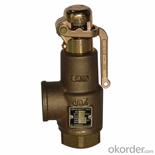
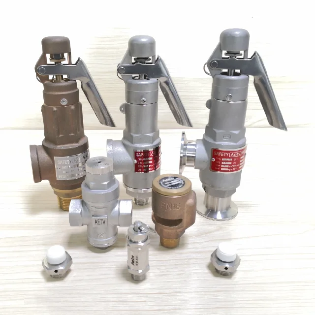
live steam safety valve made in china

The development of valves is closely related to the development of industrial production processes. In ancient times, large stones and trunks were used to impede or change the direction of the flow of rivers or creeks. And as early as the end of the Warring States Period, Li Bing, the governor of Qinshu County had already dug a salt well in the Chengdu Plain and used a bamboo-made valve for drawing brine.
The ancient Egyptians and Greeks invented several original valves for crop irrigation, etc. It is generally accepted that the ancient Romans invented and developed a rather complex crop irrigation system that used plug valves, plunger valves, and check valves to prevent water backflow.
During the Renaissance, in the design of the artist and inventor Da Vinci, valves were used in the canals, irrigation projects and other large hydraulic systems, and many of his technical solutions still exist. Subsequently, in Europe, the requirements for valves became gradually strict due to the development of technology and hydraulic machinery. Metal valves, like copper and aluminum plug valveswere created in this time.
The modern history of the valve industry is in parallel with the industrial revolution. In 1712, Thomas Newcomen invented the first practical steam engine which put control requirements on the operation of the steam engine. From 1763 to 1776, James Watt improved the engine and valves, including plug valves, safety valves, check valves and butterfly valves used on steam engines, officially entered the mechanical industry.
In the 1960s, the economies of developed, industrialized countries went into a period of prosperity. Countries such as West Germany, Japan, Italy, France, and the United Kingdom were eager to find an international market so as to export their products, including complete sets of machinery and equipment, which drove the export of valves.
From the late 1960s to the early 1980s, many colonial countries were independent, for developing their industries, they imported large quantities of equipment, including valves. Besides, the oil crisis caused oil-producing countries to invest heavily in the highly profitable oil industry. These were reasons that the international valve production and trade were rapidly developing during that period of time.
China"s valve industry production started from the 1960s, and mostly imitated the products from the former Soviet Union. Because of the backwardness of machinery industry and low accuracy of machining, valves made in China at that time had large leakage and could not meet the general control requirements of the industrial production process.
Since the 1970s, with the expansion of industrial production and the improvement of industrial process control requirements, some regulating valves were unable to meet the requirements of high pressure, high-pressure drop, low and high temperature, conveying corrosive media. Because of these, some large petrochemical enterprises imported equipment with control valves, like sleeve valves with balanced plug, eccentric rotary valves, etc. Those imported valves pointed out the development direction for domestic control valve manufacturers, and some of them began to model on those products.
Started from the 1980s, with the implementation of reform and opening up policy, China had organized major enterprises to import and learn from advanced technique, design and equipment from other countries, so the quality of valve and manufacturing technique had been rapidly improved. With the progress of industrial projects such as large power stations, various electro-hydraulic actuators, long-stroke actuators, etc. had been developed to meet the control requirements.
In the 1990s, China"s regulating valve industry began to develop rapidly after introducing foreign advanced technologies, filling some blank space and shortening the gap with other countries. At present, many valves production enterprises in China have been able to design and manufacture various kinds of valves in accordance with ISO, DIN, AWWA and other standards, some of which have reached the international advanced level.
For outlining, valves are a kind of control components in pipeline transportation systems, including shut-off valves with the simplest structure and various valves used in extremely complex automatic control systems, such as ball valves, butterfly valves, gate valves, globe valves, check valves, safety valves, plug valves, etc. Valves can be used to control the flow of different kinds of fluids such as air, water, mud, oil, liquid metals, radioactive media, corrosive media. The distribution of the valve market is mainly based on the construction of engineering projects, industries, among which the biggest users are petrochemical, electric power, metallurgical, chemical and construction industries。

As soon as mankind was able to boil water to create steam, the necessity of the safety device became evident. As long as 2000 years ago, the Chinese were using cauldrons with hinged lids to allow (relatively) safer production of steam. At the beginning of the 14th century, chemists used conical plugs and later, compressed springs to act as safety devices on pressurised vessels.
Early in the 19th century, boiler explosions on ships and locomotives frequently resulted from faulty safety devices, which led to the development of the first safety relief valves.
In 1848, Charles Retchie invented the accumulation chamber, which increases the compression surface within the safety valve allowing it to open rapidly within a narrow overpressure margin.
Today, most steam users are compelled by local health and safety regulations to ensure that their plant and processes incorporate safety devices and precautions, which ensure that dangerous conditions are prevented.
The principle type of device used to prevent overpressure in plant is the safety or safety relief valve. The safety valve operates by releasing a volume of fluid from within the plant when a predetermined maximum pressure is reached, thereby reducing the excess pressure in a safe manner. As the safety valve may be the only remaining device to prevent catastrophic failure under overpressure conditions, it is important that any such device is capable of operating at all times and under all possible conditions.
Safety valves should be installed wherever the maximum allowable working pressure (MAWP) of a system or pressure-containing vessel is likely to be exceeded. In steam systems, safety valves are typically used for boiler overpressure protection and other applications such as downstream of pressure reducing controls. Although their primary role is for safety, safety valves are also used in process operations to prevent product damage due to excess pressure. Pressure excess can be generated in a number of different situations, including:
The terms ‘safety valve’ and ‘safety relief valve’ are generic terms to describe many varieties of pressure relief devices that are designed to prevent excessive internal fluid pressure build-up. A wide range of different valves is available for many different applications and performance criteria.
In most national standards, specific definitions are given for the terms associated with safety and safety relief valves. There are several notable differences between the terminology used in the USA and Europe. One of the most important differences is that a valve referred to as a ‘safety valve’ in Europe is referred to as a ‘safety relief valve’ or ‘pressure relief valve’ in the USA. In addition, the term ‘safety valve’ in the USA generally refers specifically to the full-lift type of safety valve used in Europe.
Pressure relief valve- A spring-loaded pressure relief valve which is designed to open to relieve excess pressure and to reclose and prevent the further flow of fluid after normal conditions have been restored. It is characterised by a rapid-opening ‘pop’ action or by opening in a manner generally proportional to the increase in pressure over the opening pressure. It may be used for either compressible or incompressible fluids, depending on design, adjustment, or application.
Safety valves are primarily used with compressible gases and in particular for steam and air services. However, they can also be used for process type applications where they may be needed to protect the plant or to prevent spoilage of the product being processed.
Relief valve - A pressure relief device actuated by inlet static pressure having a gradual lift generally proportional to the increase in pressure over opening pressure.
Relief valves are commonly used in liquid systems, especially for lower capacities and thermal expansion duty. They can also be used on pumped systems as pressure overspill devices.
Safety relief valve - A pressure relief valve characterised by rapid opening or pop action, or by opening in proportion to the increase in pressure over the opening pressure, depending on the application, and which may be used either for liquid or compressible fluid.
In general, the safety relief valve will perform as a safety valve when used in a compressible gas system, but it will open in proportion to the overpressure when used in liquid systems, as would a relief valve.
Safety valve- A valve which automatically, without the assistance of any energy other than that of the fluid concerned, discharges a quantity of the fluid so as to prevent a predetermined safe pressure being exceeded, and which is designed to re-close and prevent further flow of fluid after normal pressure conditions of service have been restored.
Pressure relief valves (safety relief valves) are designed to open at a preset pressure and discharge fluid until pressure drops to acceptable levels. The development of the safety relief valve has an interesting history.
Denis Papin is credited by many sources as the originator of the first pressure relief valve (circa 1679) to prevent overpressure of his steam powered “digester”. His pressure relief design consisted of a weight suspended on a lever arm. When the force of the steam pressure acting on the valve exceeded the force of the weight acting through the lever arm the valve opened. Designs requiring a higher relief pressure setting required a longer lever arm and/or larger weights. This simple system worked however more space was needed and it coud be easily tampered with leading to a possible overpressure and explosion. Another disadvantage was premature opening of the valve if the device was subjected to bouncing movement.
Direct-acting deadweight pressure relief valves: Later to avoid the disadvantages of the lever arrangement, direct-acting deadweight pressure relief valves were installed on early steam locomotives. In this design, weights were applied directly to the top of the valve mechanism. To keep the size of the weights in a reasonable range, the valve size was often undersized resulting in a smaller vent opening than required. Often an explosion would occur as the steam pressure rose faster than the vent could release excess pressure. Bouncing movements also prematurely released pressure.
Direct acting spring valves: Timothy Hackworth is believed to be the first to use direct acting spring valves (circa 1828) on his locomotive engine called the Royal George. Timothy utilized an accordion arrangement of leaf springs, which would later be replaced with coil springs, to apply force to the valve. The spring force could be fine tuned by adjusting the nuts retaining the leaf springs.
Refinements to the direct acting spring relief valve design continued in subsequent years in response to the widespread use of steam boilers to provide heat and to power locomotives, river boats, and pumps. Steam boilers are less common today but the safety relief valve continues to be a critical component, in systems with pressure vessels, to protect against damage or catastrophic failure.
Each application has its own unique requirements but before we get into the selection process, let’s have a look at the operating principles of a typical direct acting pressure relief valve.
In operation, the pressure relief valve remains normally closed until pressures upstream reaches the desired set pressure. The valve will crack open when the set pressure is reached, and continue to open further, allowing more flow as over pressure increases. When upstream pressure falls a few psi below the set pressure, the valve will close again.
Most commonly, pressure relief valves employ a spring loaded “poppet” valve as a valve element. The poppet includes an elastomeric seal or, in some high pressure designs a thermoplastic seal, which is configured to make a seal on a valve seat. In operation, the spring and upstream pressure apply opposing forces on the valve. When the force of the upstream pressure exerts a greater force than the spring force, then the poppet moves away from the valve seat which allows fluid to pass through the outlet port. As the upstream pressure drops below the set point the valve then closes.
Piston style designs are often used when higher relief pressures are required, when ruggedness is a concern or when the relief pressure does not have to be held to a tight tolerance. Piston designs tend to be more sluggish, compared to diaphragm designs due to friction from the piston seal. In low pressure applications, or when high accuracy is required, the diaphragm style is preferred. Diaphragm relief valves employ a thin disc shaped element which is used to sense pressure changes. They are usually made of an elastomer, however, thin convoluted metal is used in special applications. Diaphragms essentially eliminate the friction inherent with piston style designs. Additionally, for a particular relief valve size, it is often possible to provide a greater sensing area with a diaphragm design than would be feasible with a piston style design.
The reference force element is usually a mechanical spring. This spring exerts a force on the sensing element and acts to close the valve. Many pressure relief valves are designed with an adjustment which allows the user to adjust the relief pressure set-point by changing the force exerted by the reference spring.
The chemical properties of the fluid should be considered before determining the best materials for your application. Each fluid will have its own unique characteristics so care must be taken to select the appropriate body and seal materials that will come in contact with the fluid. The parts of the pressure relief valve in contact with the fluid are known as the “wetted” components. If the fluid is flammable or hazardous in nature the pressure relief valve must be capable of discharging it safely.
In many high technology applications space is limited and weight is a factor. Some manufactures specialize in miniature components and should be consulted. Material selection, particularly the relief valve body components, will impact weight. Also carefully consider the port (thread) sizes, adjustment styles, and mounting options as these will influence size and weight.
In many high technology applications space is limited and weight is a factor. Some manufactures specialize in miniature components and should be consulted. Material selection, particularly the relief valve body components, will impact weight. Also carefully consider the port (thread) sizes, adjustment styles, and mounting options as these will influence size and weight.
A wide range of materials are available to handle various fluids and operating environments. Common pressure relief valve component materials include brass, plastic, and aluminum. Various grades of stainless steel (such as 303, 304, and 316) are available too. Springs used inside the relief valve are typically made of music wire (carbon steel) or stainless steel.
The materials selected for the pressure relief valve not only need to be compatible with the fluid but also must be able to function properly at the expected operating temperature. The primary concern is whether or not the elastomer chosen will function properly throughout the expected temperature range. Additionally, the operating temperature may affect flow capacity and/or the spring rate in extreme applications.
Beswick Engineering manufactures four styles of pressure relief valves to best suit your application. The RVD and RVD8 are diaphragm based pressure relief valves which are suited to lower relief pressures. The RV2 and BPR valves are piston based designs.
Description: The spring type double safety valve is suitable for equipment and pipelines of steam, water and other media with working temperature ≤350 °C. As an overpressure protection device. Specification: Model: A37H, A38Y, A43H Size: DN50~DN150 Pressure: PN16~PN40...
Description: This valve is suitable for use as an overpressure protection device for equipment and pipelines with a working temperature of 300 °C for air, steam, petroleum gas and other media. When the pressure in the equipment and pipeline exceeds the allowable value, the...
Pressure Safety Valve Specification: Feature: Spring loaded Connection: Flanged Body Material: A216 WCB Size: DN32~300mm (1 1/4"~12") Pressure: 150Lb-2500Lb Design Manufacture: API 520, API 526 Pressure-Temperature Ratings: ASME B16.34 Face to Face Dimension: API...
Product Description This type at a working temperture less than 450c, and are used for the equipment and pipeliness with such media as air,petroleum gas and N2-H2 mixed gas as an overpressure protection device. Specification: Name: Flange Type Stainless Steel Safety Valve for...


 8613371530291