
locomotive safety valve factory

Kunkle Relief Valve OverviewWhen it comes to industrial and commercial safety and relief valve products, Kunkle’s valve’s catalog is second to none in steam, air, gas, and liquid applications.
Kunkle relief valves range in size from ¼” NPT to 6” flange and are suitable in cryogenic and high temperatures up to 800°F environments at vacuum to 7,500 psig pressure. Kunkle Valve’s code certifications meet several global and national board standards, including ASME Section I, Section IV, and Section VIII, PED, CRN, TU and Chinese, as well as non-code requirements.
Relief Valves for Steam ServiceSteam supplies heat for industrial and chemical processes and also is used to heat buildings, supply mechanical energy, and drive mechanical equipment. Steam moves from the boiler to the end point, then heats by direct heating or indirect heating through a heat exchanger. Kunkle steam relief valves are critical to protecting equipment such as boilers, steam lines, and pressure valves, from being over-pressurized.
Relief Valves for Air ServiceKunkle designs valves for air service, for example for air compressors in mechanical shops and small factories where either low-pressure or high-pressure air is required. NASVI stocks Kunkle relief valves for air service in iron, steel and bronze for a variety of uses.
Relief Valves for Liquid ServiceKunkle also makes valves for liquid service, which provide bypass relief in a variety of applications and liquid types.
More About KunkleKunkle Valve is a renowned pressure relief valve manufacturer. Erastus B. Kunkle invented the safety valve to prevent overpressure in locomotive engines. Kunkle patented it in 1875. Since that time, Kunkle has earned its reputation for high-quality valves, and other equipment manufacturers ship their products with Kunkle’s valves pre-installed.
NASVI has stocked Kunkle safety relief valves since we opened in 1975, so we are confident when we call ourselves Kunkle safety valve experts. Every day we fulfill orders for our customers looking for Kunkle relief valves for steam, air, gas, and liquid applications.

... -start valve with Series MX2 air treatment units without the need for additional connection interfaces. The soft-start valve is positioned upstream of the safety valves, ...
Two hands safety valve, which allows a safety use of two hands pneumatic controls (for example two push-button 3/2 N.C. to a certain distance) excluding false signals in case of push-button ...
The SI2 safety valve prevents the allowed operating pressure from being exceeded by more than 10%. If, after opening, the adjusted response pressure falls ...
... stainless steel full-lift clean service safety valve designed to AD Merkblatt A2 and TRD 421 standards and suitable for pure steam, vapour and inert gases.
Insert style flow control valves are comprised of a precision orifice in parallel with a check valve, combined into a single component. Each is designed for easy installation into metal housings using ...
Press-in style flow control valves are comprised of a precision flow orifice in parallel with a check valve, combined into a single component. Each part is designed for easy installation into plastic ...
If you have been searching for a safety release valve that you can use to reduce short-term pressure surges successfully and diminish the effects of gas leaks, this is the product for you. With a pe of ...
... have been type tested as well. These pressure regulators have safety valves which will slam shut in the event of emergencies, such as the gas reaching too high a pressure level. The valve ...
This product has hydraulically actuated class A gas safety valves to EN 161 used for automatic shut-off. It shuts off when unstimulated for gas and air, or even biologically produced methane. It has AISi ...
The S 104 Safety Shut Off valve is mainly used to avoid any damage to components as well as to avoid too high or too low pressure in the gas train. This could cause high financial losses and/or injured ...
The S50 Safety Shut Off valve is mainly used to avoid any damage to components as well as to avoid too high or too low pressure in the gas train. This could cause high financial losses and/or injured ...
The S100 Safety Shut Off valve is mainly used to avoid any damage to components as well as to avoid too high or too low pressure in the gas train. This could cause high financial losses and/or injured ...
... Pressure Safety Valve + Rupture Disk is protected and may be utilized autonomously as essential security gadgets or in conjunction. There are 3 possible combinations. The first combinations ...
Excavator pipe-rupture valves prevent uncontrolled cylinder movement in the event that a pipe or hose bursts. The ESV valve fulfills all of the requirements of the ISO 8643 and EN 474-5 standards for ...
Material: Body- CF8M; Valve Seat- CF8M Métal Seat, PTFE Soft Seat available Orifice Size: fc"(15mm), 3/4M(20mm), l"(25mm), l1/4,’(32mm)I ltë”(40mm), ...
The Safety valves from ATOS are designed to guarantee protection for application on various devices, especially those that monitor spool position. They are also recommended for hydraulic ...

In its 100-plus year history, the Ashton Valve company saved countless lives by producing safety and relief valves, gauges of all types, testing equipment, whistles, clocks and other steam-related products for railroads, marine ships and power stations.
He worked for Hinkley Locomotive Works and the Eagle Sugar Refinery before inventing his lock pop safety valve in 1871. It was a breakthrough in boiler safety. Basically, the safety valve would close quickly after “popping,” saving a lot of steam. The boiler would then be able to get up to steam much quicker. Time is money, as they say.
Henry patented his idea and in 1872 started producing the valves with three other employees at 138 Pearl St. Burned out by the great Boston Fire of 1872, the company relocated to other Boston addresses until settling down at 271 Franklin St., its home for the next 27 years.
The demand for its products grew. In 1885, the Railway Purchasing Agent journal quoted the company as stating “Ashton Valve has not discharged a man on account of any falling off in orders, nor run less than 10 hours a day during the last four years.”
“The reputation gained by nearly 20 years experience in the manufacture of safety valves and the widely recognized quality of the Ashton Valve company will be the only guarantee needed for the unsurpassed quality of the goods we shall put upon the market,” the company announced.
Before long, the company’s gauges commanded as much respect throughout the industry as its valves. The business continued to grow at a rapid pace with a reputation based on quality products. Its motto, “higher in first cost, but cheaper in the end.”
Despite adding a fifth floor to the Franklin Street facility in 1900, the company could not keep up with demand. So in 1907 Ashton Valve purchased a dirt lot in East Cambridge. It then contracted the Densmore and LeClear company to design a four-story, 45,820 sq. ft. building. Located at 161 First St., the building still stands today. It cost $67,000 in 1907 money for C.A. Dodge & Company to build, and it featured modern bathrooms and electricity throughout.
By 1922 Ashton Valve employed 250 workers. 1922 also saw the death of Albert Ashton, who had been running the company since his father’s death in 1895. The 1920s and 1930s represented the peak years for the company. And the profits were good. In 1916, it showed a profit of $182,234, and in 1919 $214,178–in the millions by today’s dollars.
Then business slowed in the 1940s as diesel locomotives, the rise in gasoline usage and electricity as a power source quickly replaced steam. The steam era was coming to a close and the company suffered because it never ventured far from its steam-related products.
A letter from the Ashton management to the shareholders explains how the DPC would affect Ashton Valve. Basically, the DPC would purchase the Ashton Valve factory and Ashton Valve would then merge with another valve producer, Crosby Valve. Crosby Valve would run the two companies at the Ashton facility.
Crosby/Ashton produced safety valves and relief valves for navy ships for the duration of the war. The safety valves used by the government ship builders were most likely the same valves Ashton had been selling to them since 1872. Then Ashton Valve had received government approval for the valve’s usage on military vessels. The valve design had not changed much since then.
After the war ended in 1945, Ashton and Crosby were both purchased by Dewey David Stone, a businessman who owned multiple companies including Converse Rubber. Both companies moved to Wrentham, Mass., in 1948. They occupied the old Winter Brothers tap and die factory. They continued to produce valves under the Crosby/Ashton name and gauges under the Ashton Valve name. The last gauges under the Ashton name were produced in 1978. The Wrentham factory was torn down in 2012.
Today the company is known more for its beautiful gauges that demand a high price on eBay than for its life saving safety valves. If you happen to be driving down First Street in Cambridge you can see the granite lintel on the building. It proudly states, “Ashton Valve 1907.”
Rick Ashton, the author of this story, has retired and lives on an island off the coast of Maine. “I am currently continuing my research on my ancestors and the Ashton Valve company they created, as well as enjoying reading and listening to music,” he said. “Probably the most enjoyable part of researching the company is the wonderful people I have met along the way. Their encouragement and help has made it a great experience. I do not miss work.”

At almost every show I attend, I ask a few engine owners and operators if they are satisfied with their new-style safety valves. It would be only a small exaggeration to say that I get just two responses. “I have been using a new-style valve for 15 years and I haven’t had any trouble with it” or “They are junk!” I have cleaned up the second response to spare the reader the unpleasant expletives.
As the result of these conversations, I have attempted to understand why there is such a discrepancy between the reactions to modern safety valves. It now appears that there are a few simple steps we can take when purchasing and installing these valves that might improve our satisfaction with the new-style valves, which are the only ones currently available.
To understand the issues involved in the selection of a safety valve, it is necessary to review the history of safety valves used on hand-fired boilers. I am referring to hand-fired boilers rather than historical boilers because the issues are determined by how the boilers are fired, not how they are constructed or how old they are. The requirements for a modern welded boiler made to the American Society of Mechanical Engineers (ASME) code are the same as for a 100-year-old riveted boiler, if both boilers are hand-fired. The requirements for a safety valve for a boiler that is automatically fired are dramatically different.
With automatic firing, the safety valve’s function as defined by Anderson Greenwood Crosby, a manufacturer of modern safety valves, is to protect life and property if all other safety measures fail. A safety valve on a hand-fired boiler, as defined by ASME almost a hundred years ago, is to give notice of the highest pressure permissible and to give alarm that more water or less fuel is needed. (The evolution of the purpose of the safety valve is summarized in “The Purpose of a Safety Valve,” at the end of this article.)
When hand-fired boilers, such as found on traction engines, steam cranes and locomotives disappeared, most of the boilers that remained were automatically fired. The safety valve manufacturers adapted their designs accordingly. The old-style valves with bottom guided, beveled seats were capable of withstanding vibration and operating near their setpoint, and were replaced by smaller top-guided valves with flat seats.
At the same time, steam system designs were adapted so there was no need to operate within 10 percent of the setpoint of the safety valve. Not all old-style valves had beveled seats, but the ones that didn’t were designed much differently from the modern flat-seated valves.
When I speak of a modern-style safety valve, I am referring to a valve shown in the second diagram of this article’s image gallery. An example of an old-style safety valve can also be seen in the image gallery. Changes in the design of safety valves had a dramatic effect on their capacity in pounds of steam per hour. If a boiler built in 1920 required a valve capable of releasing 1,000 pounds of steam per hour at a pressure of 100 pounds per square inch, it would have been equipped with a 2-inch safety valve. Today, 3/4-inch valves are available to release that much steam at that pressure.
The evolution of the safety valve did not end with the development of the modern, flat-seated valve. In the last 20 years, the design of safety valves has continued to evolve.
In 1985, a new-style 3/4-inch valve set at 150 pounds per square inch could have a capacity of 1,497 pounds of steam per hour. In 2002 this same valve could have a capacity of 1,651 pounds of steam per hour.
From 1914 until 1998, the blowdown allowed by the ASME boiler code was 2 to 4 percent of the setpoint. In 1998, this was changed to allow the blowdown to be as high as 6 percent. Beginning with the 2004 ASME code, there is no limit on blowdown. The code has not required that the amount of blowdown be stamped on a safety valve since 1986.
When I asked owners and operators how well they liked their new-style safety valves, I was not aware of the need to ask about the age of the valve. Instead, I would ask about the amount of blowdown. In almost every case, the people who were satisfied had valves that would blowdown 4 percent or less. It appears that this is almost the same as if I had asked the age of the valve. If the valve were purchased prior to 1998, it would have been set for 4 percent blowdown. If purchased after that date, unless specified otherwise, it would have been set for 6 percent. The change from 4 to 6 percent causes a 50 percent increase in the amount the pressure changes in a boiler each time the valve pops. The resulting increase in the flexing of the components of the boiler may be associated with a corresponding increase in seepage at stay bolts and tubes.
When you order a new safety valve, you will need to provide four pieces of information: the setpoint, the capacity in pounds of steam per hour, the blowdown and the requirement that the valve be stamped with the ASME “V” stamp. If you specify the pipe size, you may get a valve with far too much capacity, as I have already explained. To determine the capacity you need, do not use the capacity stamped on the old valve. First, if the valve has been replaced, it might not be the right capacity. Secondly, the capacity stamped on the valve is probably the capacity of the smallest valve available and might be significantly larger than the required capacity.
As I talked to many owners, they would offer other comments regarding their valves. One comment I heard from several owners who were satisfied with the new-style valves was that their valves were larger in pounds per hour than the minimum required by the ASME code. I am not certain as to exactly how the capacity affects the operation of the valve. What I do know is the larger the valve, the more force it takes to raise it off its seat. The force of the steam on the boiler-side of the valve cannot overcome the force of the spring in the safety valve until the pressure in the boiler rises to the setpoint of the valve.
When this happens, the valve pops open. It seems the larger diameter, and thus the greater forces, may result in more stable operation of the valve near its setpoint. There is a concern in the boiler code that safety valves should not be so large that water is drawn out of the boiler. It would seem, because of the relatively small size of portable and traction boilers, the pressure would drop so quickly that little water, if any, would be lost. I have seen boilers where the owners have installed modern safety valves of the same pipe size as the old style valves installed by the factory. The capacity of these valves was far greater than I believe anyone would recommend, but I am not aware that they caused water to be discharged from the boiler. It is important to be careful when sizing a safety valve. I suggest owners talk to each other and share their experiences before making such a decision.
If you would prefer to have a top-discharge safety valve, which looks more authentic, shop around. They are available in a few sizes. You might also want to consider specifying that the valve have a non-metallic seat.
When installing a safety valve, do not install any fitting smaller than the inlet to the valve and do not install any kind of valve between the safety valve and the boiler. Examples of what not to do can be seen in the image gallery. Do not use a pipe wrench on a safety valve, it can damage or destroy the valve.
Once you have carefully selected your safety valve and have installed it on your boiler, it is important to verify the setpoint and the blowdown have been set according to your specifications. The first step in this process is to have the accuracy of your steam gauge checked with a dead-weight gauge tester. If your gauge does not agree with the setpoint of your new safety valve do not assume that the gauge is wrong.
Do not use the lifting lever to lift the valve from its seat until the boiler pressure is up to 75 percent of the setpoint of the valve. If the valve is lifted from its seat at a lower pressure, any dirt or foreign material in the valve might not be blown clear of the seat and could damage the seats when the valve closes.
Because new-style safety valves are not designed to be operated within 10 percent of their setpoint, many owners have elected to install the new valve along with an old-style valve. In doing so, the old style valve operates in the range of 5 to 10 percent below the setpoint of the new valve. With this arrangement, the new valve satisfies the code requirements while the old-style valve performs the function for which it was designed. Two possible arrangements can be seen in the image gallery.
In response to complaints from owners of historical boilers who had recently purchased new safety valves, Dean Jagger, Ohio’s chief boiler inspector, requested that the National Board test valves from the manufacturer to determine if the valves complied with the requirements of the ASME boiler code. As a result of these tests the Ohio Department of Commerce issued a safety notice:
“The State of Ohio Boiler Division has been made aware of the fact that some recently purchased Kunkle safety valves, which were assembled by Allied Industries, have been tested by the National Board Testing Laboratory and found not to be in compliance. The tests indicated that the valves blowdown and setpoint pressure settings were out of tolerance as established by Section I of the ASME Boiler Code.”
This may be an indication that all of the problems with modern safety valves are not entirely the result of design issues, but insufficient oversight of manufacturing and quality control processes may also be a factor. A new valve may be “junk” as has been so often alleged.
The errors found by the National Board Laboratories were significant. One of the valves was stamped 165 psi but popped low at 148.8 psi. Another was stamped 150 psi and popped high at 164.5 psi. On the other three valves the pop was consistent with the setting stamped on the valve. The 2001 edition of the ASME Boiler Code specifies that for pressures from 70 to 300 psi the tolerance, plus or minus from the set pressure, shall not exceed 3 percent of the set pressure. The 165 psi valve popped 9.6 percent below the set pressure stamped on the valve, and the 150 psi valve popped 9.7 percent above the set pressure stamped on the valve.
The blowdowns on all of the valves that were tested were out of tolerance. The 2001 edition of the ASME Boiler Code specifies that for pressures from 67 to 250 psi the blowdown shall not be greater than 6 percent of the set pressure. With such a wide range of variations in both setpoint and blowdown, in a sample of just five valves, it seems reasonable to suspect that even greater variations may exist. The results of the tests are shown in the image gallery.
Complaints about quality problems are not limited to the five valves recently tested by the National Board; for example, an engine owner told me of purchasing a new 1-1/4-inch valve stamped 175 psi. When installed on a traction engine, the valve consistently popped at 185 psi and blew down 15 psi. (A pressure of 11.1 psi equals the allowed 6 percent.) The manufacturer told the owner that the valve had been tested properly prior to shipment but accepted it back. The owner had verified the accuracy of the pressure gauge prior to contacting the manufacturer.
The ASME and National Board procedures for safety valves merely confirm the adequacy of the design of the valve and do not assure the adequacy of production and quality control practices. Each boiler owner and operator must carefully confirm the accuracy of the setpoint and blowdown on every safety valve and not rely on the ASME and National Board stamps as assurances of quality. At this time, I have no reason to believe the monitoring of the ASME and National Board requirements at other valve manufacturers and assemblers is any different than what existed at Kunkle and Allied.
One scenario that concerns me is the owner who installs a new safety valve on his boiler and, seeing that the pop does not coincide with the reading on his 80- or 100-year-old gauge, decides that obviously his gauge must be wrong. This is a conclusion I am sure I would have considered when I first began my study of safety valves.
Incorrect settings of safety valves are more likely to be detected when the valves are used on hand-fired boilers than when used on modern boilers. If the controls on a modern boiler are to limit the pressure to 10 percent or more below the setpoint of the safety valve, the valve can be set as much as 10 percent below its rating and the error might not be apparent. Errors above the setpoint also wouldn’t be obvious even if the boiler were operated up to the setpoint stamped on the valve. Also, incorrect setting of the blowdown would not be apparent until the valve had operated.
1909: “The function of the safety valve is two fold: (A) it gives notice of the highest pressure permissible; (B) it gives alarm that more water or less fuel is needed.”
Today: “A PRV (pressure relief valve) is a safety device intended to protect life and property if all other safety measures fail.” – Anderson Greenwood Crosby, 2001 (safety valve manufactuer)
A safety valve is a valve that acts as a fail-safe. An example of safety valve is a pressure relief valve (PRV), which automatically releases a substance from a boiler, pressure vessel, or other system, when the pressure or temperature exceeds preset limits. Pilot-operated relief valves are a specialized type of pressure safety valve. A leak tight, lower cost, single emergency use option would be a rupture disk.
Safety valves were first developed for use on steam boilers during the Industrial Revolution. Early boilers operating without them were prone to explosion unless carefully operated.
Vacuum safety valves (or combined pressure/vacuum safety valves) are used to prevent a tank from collapsing while it is being emptied, or when cold rinse water is used after hot CIP (clean-in-place) or SIP (sterilization-in-place) procedures. When sizing a vacuum safety valve, the calculation method is not defined in any norm, particularly in the hot CIP / cold water scenario, but some manufacturers
The earliest and simplest safety valve was used on a 1679 steam digester and utilized a weight to retain the steam pressure (this design is still commonly used on pressure cookers); however, these were easily tampered with or accidentally released. On the Stockton and Darlington Railway, the safety valve tended to go off when the engine hit a bump in the track. A valve less sensitive to sudden accelerations used a spring to contain the steam pressure, but these (based on a Salter spring balance) could still be screwed down to increase the pressure beyond design limits. This dangerous practice was sometimes used to marginally increase the performance of a steam engine. In 1856, John Ramsbottom invented a tamper-proof spring safety valve that became universal on railways. The Ramsbottom valve consisted of two plug-type valves connected to each other by a spring-laden pivoting arm, with one valve element on either side of the pivot. Any adjustment made to one of valves in an attempt to increase its operating pressure would cause the other valve to be lifted off its seat, regardless of how the adjustment was attempted. The pivot point on the arm was not symmetrically between the valves, so any tightening of the spring would cause one of the valves to lift. Only by removing and disassembling the entire valve assembly could its operating pressure be adjusted, making impromptu "tying down" of the valve by locomotive crews in search of more power impossible. The pivoting arm was commonly extended into a handle shape and fed back into the locomotive cab, allowing crews to "rock" both valves off their seats to confirm they were set and operating correctly.
Safety valves also evolved to protect equipment such as pressure vessels (fired or not) and heat exchangers. The term safety valve should be limited to compressible fluid applications (gas, vapour, or steam).
For liquid-packed vessels, thermal relief valves are generally characterized by the relatively small size of the valve necessary to provide protection from excess pressure caused by thermal expansion. In this case a small valve is adequate because most liquids are nearly incompressible, and so a relatively small amount of fluid discharged through the relief valve will produce a substantial reduction in pressure.
Flow protection is characterized by safety valves that are considerably larger than those mounted for thermal protection. They are generally sized for use in situations where significant quantities of gas or high volumes of liquid must be quickly discharged in order to protect the integrity of the vessel or pipeline. This protection can alternatively be achieved by installing a high integrity pressure protection system (HIPPS).
In the petroleum refining, petrochemical, chemical manufacturing, natural gas processing, power generation, food, drinks, cosmetics and pharmaceuticals industries, the term safety valve is associated with the terms pressure relief valve (PRV), pressure safety valve (PSV) and relief valve.
The generic term is Pressure relief valve (PRV) or pressure safety valve (PSV). PRVs and PSVs are not the same thing, despite what many people think; the difference is that PSVs have a manual lever to open the valve in case of emergency.
Relief valve (RV): an automatic system that is actuated by the static pressure in a liquid-filled vessel. It specifically opens proportionally with increasing pressure
Pilot-operated safety relief valve (POSRV): an automatic system that relieves on remote command from a pilot, to which the static pressure (from equipment to protect) is connected
Low pressure safety valve (LPSV): an automatic system that relieves static pressure on a gas. Used when the difference between the vessel pressure and the ambient atmospheric pressure is small.
Vacuum pressure safety valve (VPSV): an automatic system that relieves static pressure on a gas. Used when the pressure difference between the vessel pressure and the ambient pressure is small, negative and near to atmospheric pressure.
Low and vacuum pressure safety valve (LVPSV): an automatic system that relieves static pressure on a gas. Used when the pressure difference is small, negative or positive and near to atmospheric pressure.
In most countries, industries are legally required to protect pressure vessels and other equipment by using relief valves. Also, in most countries, equipment design codes such as those provided by the ASME, API and other organizations like ISO (ISO 4126) must be complied with. These codes include design standards for relief valves and schedules for periodic inspection and testing after valves have been removed by the company engineer.
Today, the food, drinks, cosmetics, pharmaceuticals and fine chemicals industries call for hygienic safety valves, fully drainable and Cleanable-In-Place. Most are made of stainless steel; the hygienic norms are mainly 3A in the USA and EHEDG in Europe.
The first safety valve was invented by Denis Papin for his steam digester, an early pressure cooker rather than an engine.steelyard" lever a smaller weight was required, also the pressure could easily be regulated by sliding the same weight back and forth along the lever arm. Papin retained the same design for his 1707 steam pump.Greenwich in 1803, one of Trevithick"s high-pressure stationary engines exploded when the boy trained to operate the engine left it to catch eels in the river, without first releasing the safety valve from its working load.
Although the lever safety valve was convenient, it was too sensitive to the motion of a steam locomotive. Early steam locomotives therefore used a simpler arrangement of weights stacked directly upon the valve. This required a smaller valve area, so as to keep the weight manageable, which sometimes proved inadequate to vent the pressure of an unattended boiler, leading to explosions. An even greater hazard was the ease with which such a valve could be tied down, so as to increase the pressure and thus power of the engine, at further risk of explosion.
Although deadweight safety valves had a short lifetime on steam locomotives, they remained in use on stationary boilers for as long as steam power remained.
Weighted valves were sensitive to bouncing from the rough riding of early locomotives. One solution was to use a lightweight spring rather than a weight. This was the invention of Timothy Hackworth on his leaf springs.
These direct-acting spring valves could be adjusted by tightening the nuts retaining the spring. To avoid tampering, they were often shrouded in tall brass casings which also vented the steam away from the locomotive crew.
The Salter coil spring spring balance for weighing, was first made in Britain by around 1770.spring steels to make a powerful but compact spring in one piece. Once again by using the lever mechanism, such a spring balance could be applied to the considerable force of a boiler safety valve.
The spring balance valve also acted as a pressure gauge. This was useful as previous pressure gauges were unwieldy mercury manometers and the Bourdon gauge had yet to be invented.
Paired valves were often adjusted to slightly different pressures too, a small valve as a control measure and the lockable valve made larger and permanently set to a higher pressure, as a safeguard.Sinclair for the Eastern Counties Railway in 1859, had the valve spring with pressure scale behind the dome, facing the cab, and the locked valve ahead of the dome, out of reach of interference.
In 1855, John Ramsbottom, later locomotive superintendent of the LNWR, described a new form of safety valve intended to improve reliability and especially to be tamper-resistant. A pair of plug valves were used, held down by a common spring-loaded lever between them with a single central spring. This lever was characteristically extended rearwards, often reaching into the cab on early locomotives. Rather than discouraging the use of the spring lever by the fireman, Ramsbottom"s valve encouraged this. Rocking the lever freed up the valves alternately and checked that neither was sticking in its seat.
A drawback to the Ramsbottom type was its complexity. Poor maintenance or mis-assembly of the linkage between the spring and the valves could lead to a valve that no longer opened correctly under pressure. The valves could be held against their seats and fail to open or, even worse, to allow the valve to open but insufficiently to vent steam at an adequate rate and so not being an obvious and noticeable fault.Rhymney Railway, even though the boiler was almost new, at only eight months old.
Naylor valves were introduced around 1866. A bellcrank arrangement reduced the strain (percentage extension) of the spring, thus maintaining a more constant force.L&Y & NER.
All of the preceding safety valve designs opened gradually and had a tendency to leak a "feather" of steam as they approached "blowing-off", even though this was below the pressure. When they opened they also did so partially at first and didn"t vent steam quickly until the boiler was well over pressure.
The quick-opening "pop" valve was a solution to this. Their construction was simple: the existing circular plug valve was changed to an inverted "top hat" shape, with an enlarged upper diameter. They fitted into a stepped seat of two matching diameters. When closed, the steam pressure acted only on the crown of the top hat, and was balanced by the spring force. Once the valve opened a little, steam could pass the lower seat and began to act on the larger brim. This greater area overwhelmed the spring force and the valve flew completely open with a "pop". Escaping steam on this larger diameter also held the valve open until pressure had dropped below that at which it originally opened, providing hysteresis.
These valves coincided with a change in firing behaviour. Rather than demonstrating their virility by always showing a feather at the valve, firemen now tried to avoid noisy blowing off, especially around stations or under the large roof of a major station. This was mostly at the behest of stationmasters, but firemen also realised that any blowing off through a pop valve wasted several pounds of boiler pressure; estimated at 20 psi lost and 16 lbs or more of shovelled coal.
Pop valves derived from Adams"s patent design of 1873, with an extended lip. R. L. Ross"s valves were patented in 1902 and 1904. They were more popular in America at first, but widespread from the 1920s on.
Although showy polished brass covers over safety valves had been a feature of steam locomotives since Stephenson"s day, the only railway to maintain this tradition into the era of pop valves was the GWR, with their distinctive tapered brass safety valve bonnets and copper-capped chimneys.
Developments in high-pressure water-tube boilers for marine use placed more demands on safety valves. Valves of greater capacity were required, to vent safely the high steam-generating capacity of these large boilers.Naylor valve) became more critical.distilled feedwater and also a scouring of the valve seats, leading to wear.
High-lift safety valves are direct-loaded spring types, although the spring does not bear directly on the valve, but on a guide-rod valve stem. The valve is beneath the base of the stem, the spring rests on a flange some height above this. The increased space between the valve itself and the spring seat allows the valve to lift higher, further clear of the seat. This gives a steam flow through the valve equivalent to a valve one and a half or twice as large (depending on detail design).
The Cockburn Improved High Lift design has similar features to the Ross pop type. The exhaust steam is partially trapped on its way out and acts on the base of the spring seat, increasing the lift force on the valve and holding the valve further open.
To optimise the flow through a given diameter of valve, the full-bore design is used. This has a servo action, where steam through a narrow control passage is allowed through if it passes a small control valve. This steam is then not exhausted, but is passed to a piston that is used to open the main valve.
There are safety valves known as PSV"s and can be connected to pressure gauges (usually with a 1/2" BSP fitting). These allow a resistance of pressure to be applied to limit the pressure forced on the gauge tube, resulting in prevention of over pressurisation. the matter that has been injected into the gauge, if over pressurised, will be diverted through a pipe in the safety valve, and shall be driven away from the gauge.
There is a wide range of safety valves having many different applications and performance criteria in different areas. In addition, national standards are set for many kinds of safety valves.
Safety valves are required on water heaters, where they prevent disaster in certain configurations in the event that a thermostat should fail. Such a valve is sometimes referred to as a "T&P valve" (Temperature and Pressure valve). There are still occasional, spectacular failures of older water heaters that lack this equipment. Houses can be leveled by the force of the blast.
Pressure cookers usually have two safety valves to prevent explosions. On older designs, one is a nozzle upon which a weight sits. The other is a sealed rubber grommet which is ejected in a controlled explosion if the first valve gets blocked. On newer generation pressure cookers, if the steam vent gets blocked, a safety spring will eject excess pressure and if that fails, the gasket will expand and release excess pressure downwards between the lid and the pan. Also, newer generation pressure cookers have a safety interlock which locks the lid when internal pressure exceeds atmospheric pressure, to prevent accidents from a sudden release of very hot steam, food and liquid, which would happen if the lid were to be removed when the pan is still slightly pressurised inside (however, the lid will be very hard or impossible to open when the pot is still pressurised).

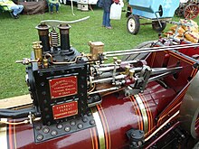
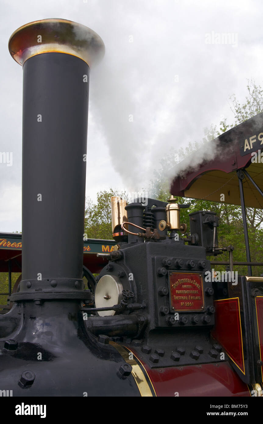
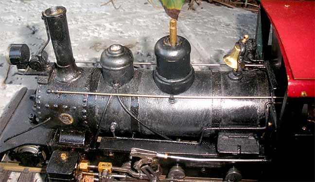
The boiler of a steam locomotive has a maximum operating pressure, which is 250 pounds per square inch (psi) in our case. It is very important that this pressure is not exceeded, as a boiler explosion would have disastrous effects. Therefore, we have safety valves on our boiler to release any excess steam pressure. The correct operation of the safety valves is so important for the safety of the boiler that the regulations state that we need at least two. We have three to ensure that excess steam can always be released quicker than it can be generated.
The three safety valves are positioned, side by side, on top of the boiler barrel, just behind the regulator dome. The middle one points directly upwards, and the other two, because of the curvature of the barrel, point slightly outwards. We set the middle one to lift first, at 250 psi, because a vertical plume of white water vapour looks better. We have the one on the fireman’s side set to lift next, very slightly above 250 psi, so that the fireman can see it. The one on the driver’s side is set to lift last, as that is more likely to dislodge debris from bridges and tunnels, obscuring the driver’s view and damaging the loco.
Our safety valves are of the Ross “pop” type. They are designed to open suddenly at the set point, which allows the fireman to keep the boiler pressure quite close to 250 psi without wasting much steam through “feathering”. They also close suddenly, making a “pop” sound – hence the name.
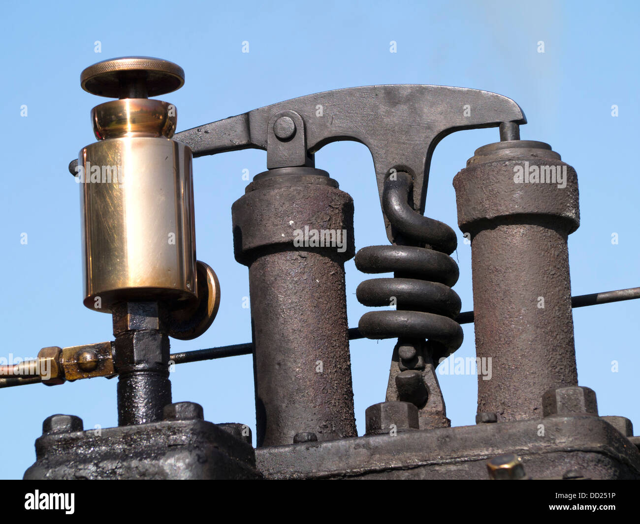
The valve is held down on to its seat by a coil spring. This, in turn, is held down by the main casing of the safety valve, which is screwed down on to the body. The valve has a guide to keep it in position, and there is an outer lip, known as the Adams Lip.
When the valve starts to lift, and steam escapes, the surface area subject to the pressurised steam is larger, because of the Adams Lip, increasing the force operating on the spring. This makes the transition from shut to feathering quite definite.
As the pressure from the feathering valve builds inside the chamber, it exerts an upward pressure on the cap. When the pressure has increased enough, the cap rises and lifts the nut slightly. This decreases the downward force on the valve, causing it to rise. As it rises, more steam escapes, the pressure in the chamber increases, and the downward force on the valve decreases even more. All this happens almost instantaneously, and this is why the safety valve lifts very suddenly.
The safety valves have to be set. There are two adjustments. The pressure at which the valve lifts is set by screwing or unscrewing the outer casing, which adjusts the compression of the spring. The number of holes in the top cap can be adjusted, which affects the threshold between the valve opening and it closing again.
The safety valves are roughly set beforehand, but the only way to set them accurately is with the engine in steam. Setting them usually requires four people. There are two on top of the firebox, setting the valves, and there are two on the footplate. One of those on the footplate is controlling the pressure, and the other is relaying the readings to those on the firebox. The people working on the safety valves have to have a lot of trust in the people on the footplate.
The boiler pressure is brought up up to see where each valve lifts, and it is then brought down again so that any adjustments can be made. This involves partially dismantling the valve. The top nut and the cap are removed first, using a screwdriver and pliers. The parts are too hot to touch, and you mustn’t put your hand over the valve, just in case it lifts unexpectedly. We then use a specially designed large spanner to turn the outer casing, and adjust the compression of the spring.
Erastus Boise Kunkle, born on December 14th, 1836, learned the machine trade from his dad. Kunkle labored in a high pressure job before inventing the relief valve.
He worked in the locomotive shops for Pennsylvania Railroad where he invented a lock-up pop safety valve, designed to release steam pressure in locomotive engines. Boiler over pressure was a serious problem, yet relief valves were unheard of at the time.
The Fort Wayne Safety Valve Works, operated by E.B. Kunkle & Company grew and a 100 years later a modified version of the original invention was still in production and the eggbeater was a standard kitchen tool .
In 1947 Kunkle Valve acquired the valve division of the Star Brass Manufacturing . The navy used Kunkle relief valves on ships and later on nuclear submarines.Valve shipments were over 1,000 a day in the 1970s.
In 1991, Kunkle Industries became a division of Anderson, Greenwood & Company. Anderson Greenwood (AGCO) is a current leader in pressure management valve solutions and has a unique back story all it’s own in aviation design.
Contact Flotech for all your valve requirements including pressure safety valves , control valves, manual valves or anything that requires an expert and/or fast turn around. Contact us for Crosby Valves, Kunkle Valves, Consolidated Relief Valve Repairs, Varecand many other Valves.

In 1872 Henry G. Ashton patented a new steam-boiler safety valve to help prevent boiler explosions. In that year, or perhaps in 1871, he established Ashton"s Lock Safety Valve Co., with C. J. Bishop, operating out of premises on Pearl Street in Boston. The 1872 Boston Fire burned them out. They relocated briefly to 9 Rowe"s Wharf, and in 1874 they relocated to 262 Purchase Street. By this time the business was doing well and Ashton continued to improve his safety valve. In 1878 or "79 they relocated briefly to 83 Federal Street but another fire forced them to move again in 1879, this time to 271 Franklin Street. Sometime during 1878 or "79 they reorganized as the Ashton Valve Co.
In 1892 they acquired the Boston Steam Gauge Co., and steam gauges would become at least as important a product line as their safety valves. They were also making other accessories for steam boilers and engines, such as a feed-water heaters and water relief valves, and they had introduced a line of steam heating valves.
Henry G. Ashton died in 1895; his son Albert, a recent engineering graduate from MIT, replaced his father as vice-president and continued running the day-to-day operations for more than a quarter century. By 1922, when Albert died, the company was at its peak, with about 250 employees and robust sales. Harry Ashton, who was sales manager, took over some of his brother"s responsibilities but as steam power became increasing obsolescent the company never expanded into other markets. In 1948 the Ashton Valve Co. merged with the Crosby Steam Gage & Valve Co.
1874 Massachusetts Register and Business Directory lists, under "Boiler Safety Apparatus", "Ashton"s Lock Safety Valve Co. C. J. Bishop, 9 Rowe"s wharf".
1875 Sampson, Davenport & Co."s Boston Directory lists "Ashton"s Lock Safety Valve Co., H. G. Ashton, patentee, C. J. Bishop. treas., 262 and 264 Purchase".
1879 Sampson, Davenport & Co."s Boston Directory lists "Ashton Valve Co., 93 Federal". H. G. Ashton was listed as owner and William Howell Reed was treasurer.
1885 Annual Report of the Executive Committee of the Western Railroad Association reports that Consolidated Safety Valve Co. was suing several others, including Ashton Valve Company, for infringing their G. W. Richardson patents 58,294 and 85,963..
1887-06-29 American Engineer has a text ad for "The Ashton Valve Co., / the Ashton noiseless blow back locomotive safety valve, / the Ashton lock safety valve, / the Ashton water relief valve..."
1890 Annual Report of the Executive Committee of the Western Railroad Association reports that Ashton Valve Company had brought suit against the Coale Muffler & Safety Valve Company for infringement of patents 200,119 and 299,504.
1907-01-01 The Plumbers Trade Journal, Steam and Hot Water Fitters" Review. "The Ashton Valve Co.—When the Ashton Valve Company, of 271 Franklin street, Boston, Mass., was organized twenty-five years ago, the officers elected were: President, Charles J. Bishop; treasurer, William Howell Reed, and Henry G. Ashton, vice-president and general manager. Since that time several changes have been made and at the present time John Avery is president; Fred A. Case, vice-president, and Albert S. Ashton, secretary-treasurer. The firm manufactures a line of well-known specialties, including pop safety valves, steam heating valves, water relief valves, and pressure and vacuum gauges."
According to patent records, Ashton Valve Co. was located in Hartford, CT., between 1900 and 1902; in Boston, MA, between 1909 and 1924; and in Cambridge, MA, between 1927 and 1938.

As soon as mankind was able to boil water to create steam, the necessity of the safety device became evident. As long as 2000 years ago, the Chinese were using cauldrons with hinged lids to allow (relatively) safer production of steam. At the beginning of the 14th century, chemists used conical plugs and later, compressed springs to act as safety devices on pressurised vessels.
Early in the 19th century, boiler explosions on ships and locomotives frequently resulted from faulty safety devices, which led to the development of the first safety relief valves.
In 1848, Charles Retchie invented the accumulation chamber, which increases the compression surface within the safety valve allowing it to open rapidly within a narrow overpressure margin.
Today, most steam users are compelled by local health and safety regulations to ensure that their plant and processes incorporate safety devices and precautions, which ensure that dangerous conditions are prevented.
The principle type of device used to prevent overpressure in plant is the safety or safety relief valve. The safety valve operates by releasing a volume of fluid from within the plant when a predetermined maximum pressure is reached, thereby reducing the excess pressure in a safe manner. As the safety valve may be the only remaining device to prevent catastrophic failure under overpressure conditions, it is important that any such device is capable of operating at all times and under all possible conditions.
Safety valves should be installed wherever the maximum allowable working pressure (MAWP) of a system or pressure-containing vessel is likely to be exceeded. In steam systems, safety valves are typically used for boiler overpressure protection and other applications such as downstream of pressure reducing controls. Although their primary role is for safety, safety valves are also used in process operations to prevent product damage due to excess pressure. Pressure excess can be generated in a number of different situations, including:
The terms ‘safety valve’ and ‘safety relief valve’ are generic terms to describe many varieties of pressure relief devices that are designed to prevent excessive internal fluid pressure build-up. A wide range of different valves is available for many different applications and performance criteria.
In most national standards, specific definitions are given for the terms associated with safety and safety relief valves. There are several notable differences between the terminology used in the USA and Europe. One of the most important differences is that a valve referred to as a ‘safety valve’ in Europe is referred to as a ‘safety relief valve’ or ‘pressure relief valve’ in the USA. In addition, the term ‘safety valve’ in the USA generally refers specifically to the full-lift type of safety valve used in Europe.
Pressure relief valve- A spring-loaded pressure relief valve which is designed to open to relieve excess pressure and to reclose and prevent the further flow of fluid after normal conditions have been restored. It is characterised by a rapid-opening ‘pop’ action or by opening in a manner generally proportional to the increase in pressure over the opening pressure. It may be used for either compressible or incompressible fluids, depending on design, adjustment, or application.
Safety valves are primarily used with compressible gases and in particular for steam and air services. However, they can also be used for process type applications where they may be needed to protect the plant or to prevent spoilage of the product being processed.
Relief valve - A pressure relief device actuated by inlet static pressure having a gradual lift generally proportional to the increase in pressure over opening pressure.
Relief valves are commonly used in liquid systems, especially for lower capacities and thermal expansion duty. They can also be used on pumped systems as pressure overspill devices.
Safety relief valve - A pressure relief valve characterised by rapid opening or pop action, or by opening in proportion to the increase in pressure over the opening pressure, depending on the application, and which may be used either for liquid or compressible fluid.
In general, the safety relief valve will perform as a safety valve when used in a compressible gas system, but it will open in proportion to the overpressure when used in liquid systems, as would a relief valve.
Safety valve- A valve which automatically, without the assistance of any energy other than that of the fluid concerned, discharges a quantity of the fluid so as to prevent a predetermined safe pressure being exceeded, and which is designed to re-close and prevent further flow of fluid after normal pressure conditions of service have been restored.

Ask anyone in the industry what brands are synonymous with high-quality safety and relief valves and you are sure to hear the name Kunkle. Kunkle Valve has long been a top manufacturer of safety and relief valves and valve products for a wide variety of commercial and industrial applications, and it all began with the building of the railroad.
Kunkle Valve’s history dates back to about 150 years ago in Fort Wayne, Indiana. It was there that machinist and inventor Erastus B. Kunkle invented the first lock-up pop safety valve. He was working on locomotives for the Pennsylvania Railroad, and at that time, overpressure in the engines could cause serious problems. Kunkle’s invention of the safety valve to release engine pressure revolutionized the industry. In 1875, Kunkle patented the invention, and the following year he and his brother-in-law entered the valve manufacturing business.
The Fort Wayne Safety Valve Works operated as such until four years after Kunkle’s death. In 1917, local Fort Wayne businessman Oscar A. Fox purchased the firm and renamed it Kunkle Valve Company.
In the decades following World War II, Kunkle Valve made an even bigger name for itself providing relief valves for navy ships, nuclear submarines, and other large nautical vessels. In 1991, Kunkle Valve became a part of Anderson, Greenwood & Company, which was later acquired by Tyco Flow Control. In 2012, Tyco Flow Control merged with Pentair Inc. to form Pentair Ltd., which today provides industrial valves, pumps, and other water and fluid solutions on a global scale.
Kunkle Valve continues to be a leading brand in the manufacture of safety and relief valves and valve products. Kunkle products are available for ASME Sections I, IV, and VIII services, and most Kunkle valves have their relief capacity certified by the National Board of Boiler and Pressure Vessel Inspectors. Kunkle safety and pressure relief valves are set and tested in accordance with the API 527 standard for seat tightness of pressure relief valves as well as Kunkle Factory seat tightness standards for air/gas, steam, and liquid service. The company also offers non-code products, which are set and tested to the customer’s specifications. Refer to the Kunkle Safety and Relief Products Technical Reference for more information.
Kunkle safety and relief valve products come in a range of sizes and materials, suitable for use in a variety of services. Explore Allied’s full line of Kunkle Valve products.
Kunkle delivers quality products from cryogenic to high temperature and vacuum to high pressure Steam, Air, Gas, and Liquid applications. Kunkle Valve provides code certifications that meet various global standards such as ASME, PED, CRN, TU and Chinese as well as non-code requirements.
Nearly 30-year handwritten note book kept by the Directors of The Consolidated Safety Valve Company, a Hartford, Connecticut based manufacturer of safety valves for steam boilers, marine engines, generators, and locomotives. The company’s manufactory was first located in Hartford, but later removed to Bridgeport in 1886. (p79) The company had offices in New York and Chicago.

Steam locomotives use boilers to generate steam. To prevent the boiler to be overpressurised a device called a safety valve is used. This releases a small amount of pressure before resealing.
Once it is printed check all of the surfaces mate correctly you should be able to blow the bottom casing and hold the valve down with little gas leakage. the same with the top casing and valve. Once put together if you blow the bottom casing the top should nudge up if you reduce the pressure the top should still hold. This is until a low enough pressure that the spring is able to close both valves with a satisfying "pop" (Hence the name).
This safety valve works by the pressure from the boiler acting on the area of the bottom valve when the blowing off pressure is reached the top lifts. the steam is now acting upon both the top and bottom valve surfaces so a significantly lower pressure must be reached before the valves shut.
As a design engineer responsible for developing and specifying boilers, dryers, furnaces, heaters, ovens and other industrial heating equipment, you face a daunting labyrinth of standards and industry regulations. Regulatory bodies sound a bit like alphabet soup, with acronyms like UL, FM, CSA, UR, AGA, ASME, ANSI, IRI, CE and NFPA tossed about. This article will help explain a common task for many thermal processing equipment specifiers: meeting the requirements of key codes — including Underwriters Laboratories (UL), Factory Mutual Insurers (FM) and the National Fire Protection Association (NFPA) — for safety valve equipment used in process heating applications.
Key to designing safety into your fuel train configurations are familiar technologies such as safety shutoff valves and vent valves as well as visual-indication mechanisms and proof-of-closure switches.
Your design skills come into play with how you take advantage of the wide range of products available. You can mix and match solenoid and safety shutoff valves — within designs from catalytic reactors to multi-zone furnaces — to create easily installed, cost-effective solutions that comply with all necessary standards. (See table.)
Make sure, however, that you start with a good grasp of valve element fundamentals. For example, examining a proof-of-closure (POC) switch underlines how reliably modern valves can ensure combustion safety. The POC unit provides an electrical contact interlocked with the controller safety circuit. In a typical design, the switch is located at the bottom of the valve, positioned to trace the stroke of the valve disc. When the disc seal reaches the fully closed position, it triggers the mechanism to push down on the contact, closing it and triggering the unit’s visual indicator to show open or closed status. As a result, the operator can act with full confidence in situations where it is critical that a safety valve be safely closed.
To provide ease of installation, many users prefer valves with modular capabilities. For example, to reduce mounting complexity, you can choose modular gas safety shut-off valves — combining a solenoid valve with an electrohydraulic motorized valve for a compact double-valve footprint, a slow-open feature and high flow rates. An accompanying actuator can provide on/off or high/low/off firing rates as well as visual indication and proof of closure for compliance with most industry standards.
Also, you may want to look for valves that include useful features such as pipe taps, which can facilitate accurate pressure readings and leakage testing.
Knowing your valve choices — and how they meet given codes and standards — can reduce the time required for design and production while facilitating compliance. This results in safer, more efficient and cost-effective heating process installations.
RMTWH30F–Relief and safety valve of turbine unit no. 1, located in the subway below the Generator Room; looking south. The safety valve was manufactured by the Chapman Valve Company of Springfield, Massachusetts. It is identical to the adjacent safety valve for turbine unit no. 2. Photo by Jet Lowe, HAER, 1989. - Puget Sound Power and Light Company, White River Hydroelectric Project, 600 North River Avenue, Dieringer, Pierce County, WA; Shuffletin, Samuel L; Stine, Charles; Webster, Edwin; Baker, Charles H
RF2C9C8DA–A pop valve or relief valve, is a type of safety valve used to control or limit the pressure in a system or relief pressure, vintage line drawing or e
RF2E2R849–Relief valve outline vector icon. Thin line black relief valve icon, flat vector simple element illustration from editable construction and tools conc
RFT8CP8C–Landschaftspark Duisburg, Germany: Close up of isolated red rusty relief control valve with flakes of peeled off paint against a white metal wall
RMP3PX80–Senior Airman Seth Bayles, a 386th Expeditionary Aircraft Maintenance Squadron aerospace ground equipment journeyman, sprays a dry lubricant on a jack tester at an undisclosed location in Southwest Asia, May 7, 2017. AGE members use the jack tester to test the relief valve on a 30-ton aircraft jack, ensuring its operational capability to reduce safety hazards to aircraft and personnel.
RF2AEP07A–Manual operated handle ball valve with focus on stem and nut of the hand wheel in mechanical workshop, at industrial plant or factory. Equipment, cabl
RMPFY0H9–. The encyclopedia of practical horticulture; a reference system of commercial horticulture, covering the practical and scientific phases of horticulture, with special reference to fruits and vegetables;. Gardening; Fruit-culture; Vegetable gardening. Fig. 3. Hardie Escape Valve Showing Com- pressor, Spring, Ball, and Seat. A neat, re- liable and durable type of safety relief valve. Longer rods are not often needed, and are cumbersome and hard to handle on ac- count of their length. Power Outfits Power outfits should be chosen accord- ing to capacity and simpli


 8613371530291