
locomotive safety valve price

After a boiler has been engineered, built and tested for a given operating pressure there is only one reliable way to prevent operation of the boiler above this design pressure. This is a safety valve. The safety valve should be sized so that a single valve can handle the maximum steam production rate of the boiler and once open prevent boiler pressure to continue to rise. Standard operating procedure for the last century has been to install two safety valves on the boiler, one set 3-5 lbs below the design pressure and one valve set at the design pressure.
The 1st valve listed below is a true adjustable differential pop valve. The differential is adjured through the differential rings lock screw hole, from 3 PSI to whatever the operator desires. The pressure of the valve can be adjusted from 40 to 200 PSI.
The other valves listed are adjustable for release pressure and have a "pop" action: The pressure differential is not adjustable on these valves. If the valves are operated above their nominal pressure, the set-reset differential increases. If operated at lower pressure, the differential decreases to the point of disappearing about 10-15% below nominal pressure.

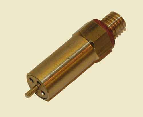
Only 5 items in stock!Add to cart[{"id":36223632769190,"title":"5\/16\" x 32","option1":"5\/16\" x 32","option2":null,"option3":null,"sku":"5055735517458","requires_shipping":true,"taxable":true,"featured_image":null,"available":true,"name":"Safety valves - 5\/16\" x 32","public_title":"5\/16\" x 32","options":["5\/16\" x 32"],"price":2450,"weight":35,"compare_at_price":null,"inventory_management":"shopify","barcode":"5055735517458","requires_selling_plan":false,"selling_plan_allocations":[]},{"id":36223632801958,"title":"5\/16\" x 40 TPI","option1":"5\/16\" x 40 TPI","option2":null,"option3":null,"sku":"5055735519216","requires_shipping":true,"taxable":true,"featured_image":null,"available":true,"name":"Safety valves - 5\/16\" x 40 TPI","public_title":"5\/16\" x 40 TPI","options":["5\/16\" x 40 TPI"],"price":2400,"weight":35,"compare_at_price":null,"inventory_management":"shopify","barcode":"5055735519216","requires_selling_plan":false,"selling_plan_allocations":[]},{"id":36223632703654,"title":"3\/8\" x 32","option1":"3\/8\" x 32","option2":null,"option3":null,"sku":"5055735502003","requires_shipping":true,"taxable":true,"featured_image":null,"available":true,"name":"Safety valves - 3\/8\" x 32","public_title":"3\/8\" x 32","options":["3\/8\" x 32"],"price":2399,"weight":30,"compare_at_price":null,"inventory_management":"shopify","barcode":"5055735502003","requires_selling_plan":false,"selling_plan_allocations":[]},{"id":36223632736422,"title":"1\/4\" x 40","option1":"1\/4\" x 40","option2":null,"option3":null,"sku":"5055735517441","requires_shipping":true,"taxable":true,"featured_image":null,"available":true,"name":"Safety valves - 1\/4\" x 40","public_title":"1\/4\" x 40","options":["1\/4\" x 40"],"price":2350,"weight":25,"compare_at_price":null,"inventory_management":"shopify","barcode":"5055735517441","requires_selling_plan":false,"selling_plan_allocations":[]},{"id":36223632670886,"title":"1\/2\" x 26","option1":"1\/2\" x 26","option2":null,"option3":null,"sku":"5055735501990","requires_shipping":true,"taxable":true,"featured_image":null,"available":true,"name":"Safety valves - 1\/2\" x 26","public_title":"1\/2\" x 26","options":["1\/2\" x 26"],"price":2750,"weight":35,"compare_at_price":null,"inventory_management":"shopify","barcode":"5055735501990","requires_selling_plan":false,"selling_plan_allocations":[]}]

The J-1 Safety Valve installed vertically in the main reservoir system vents pressure at a predetermined setting to atmosphere in order to prevent excessive main reservoir pressure buildup.its used railway.

Pressure relief valves (safety relief valves) are designed to open at a preset pressure and discharge fluid until pressure drops to acceptable levels. The development of the safety relief valve has an interesting history.
Denis Papin is credited by many sources as the originator of the first pressure relief valve (circa 1679) to prevent overpressure of his steam powered “digester”. His pressure relief design consisted of a weight suspended on a lever arm. When the force of the steam pressure acting on the valve exceeded the force of the weight acting through the lever arm the valve opened. Designs requiring a higher relief pressure setting required a longer lever arm and/or larger weights. This simple system worked however more space was needed and it coud be easily tampered with leading to a possible overpressure and explosion. Another disadvantage was premature opening of the valve if the device was subjected to bouncing movement.
Direct-acting deadweight pressure relief valves: Later to avoid the disadvantages of the lever arrangement, direct-acting deadweight pressure relief valves were installed on early steam locomotives. In this design, weights were applied directly to the top of the valve mechanism. To keep the size of the weights in a reasonable range, the valve size was often undersized resulting in a smaller vent opening than required. Often an explosion would occur as the steam pressure rose faster than the vent could release excess pressure. Bouncing movements also prematurely released pressure.
Direct acting spring valves: Timothy Hackworth is believed to be the first to use direct acting spring valves (circa 1828) on his locomotive engine called the Royal George. Timothy utilized an accordion arrangement of leaf springs, which would later be replaced with coil springs, to apply force to the valve. The spring force could be fine tuned by adjusting the nuts retaining the leaf springs.
Refinements to the direct acting spring relief valve design continued in subsequent years in response to the widespread use of steam boilers to provide heat and to power locomotives, river boats, and pumps. Steam boilers are less common today but the safety relief valve continues to be a critical component, in systems with pressure vessels, to protect against damage or catastrophic failure.
Each application has its own unique requirements but before we get into the selection process, let’s have a look at the operating principles of a typical direct acting pressure relief valve.
In operation, the pressure relief valve remains normally closed until pressures upstream reaches the desired set pressure. The valve will crack open when the set pressure is reached, and continue to open further, allowing more flow as over pressure increases. When upstream pressure falls a few psi below the set pressure, the valve will close again.
Most commonly, pressure relief valves employ a spring loaded “poppet” valve as a valve element. The poppet includes an elastomeric seal or, in some high pressure designs a thermoplastic seal, which is configured to make a seal on a valve seat. In operation, the spring and upstream pressure apply opposing forces on the valve. When the force of the upstream pressure exerts a greater force than the spring force, then the poppet moves away from the valve seat which allows fluid to pass through the outlet port. As the upstream pressure drops below the set point the valve then closes.
Piston style designs are often used when higher relief pressures are required, when ruggedness is a concern or when the relief pressure does not have to be held to a tight tolerance. Piston designs tend to be more sluggish, compared to diaphragm designs due to friction from the piston seal. In low pressure applications, or when high accuracy is required, the diaphragm style is preferred. Diaphragm relief valves employ a thin disc shaped element which is used to sense pressure changes. They are usually made of an elastomer, however, thin convoluted metal is used in special applications. Diaphragms essentially eliminate the friction inherent with piston style designs. Additionally, for a particular relief valve size, it is often possible to provide a greater sensing area with a diaphragm design than would be feasible with a piston style design.
The reference force element is usually a mechanical spring. This spring exerts a force on the sensing element and acts to close the valve. Many pressure relief valves are designed with an adjustment which allows the user to adjust the relief pressure set-point by changing the force exerted by the reference spring.
The chemical properties of the fluid should be considered before determining the best materials for your application. Each fluid will have its own unique characteristics so care must be taken to select the appropriate body and seal materials that will come in contact with the fluid. The parts of the pressure relief valve in contact with the fluid are known as the “wetted” components. If the fluid is flammable or hazardous in nature the pressure relief valve must be capable of discharging it safely.
In many high technology applications space is limited and weight is a factor. Some manufactures specialize in miniature components and should be consulted. Material selection, particularly the relief valve body components, will impact weight. Also carefully consider the port (thread) sizes, adjustment styles, and mounting options as these will influence size and weight.
In many high technology applications space is limited and weight is a factor. Some manufactures specialize in miniature components and should be consulted. Material selection, particularly the relief valve body components, will impact weight. Also carefully consider the port (thread) sizes, adjustment styles, and mounting options as these will influence size and weight.
A wide range of materials are available to handle various fluids and operating environments. Common pressure relief valve component materials include brass, plastic, and aluminum. Various grades of stainless steel (such as 303, 304, and 316) are available too. Springs used inside the relief valve are typically made of music wire (carbon steel) or stainless steel.
The materials selected for the pressure relief valve not only need to be compatible with the fluid but also must be able to function properly at the expected operating temperature. The primary concern is whether or not the elastomer chosen will function properly throughout the expected temperature range. Additionally, the operating temperature may affect flow capacity and/or the spring rate in extreme applications.
Beswick Engineering manufactures four styles of pressure relief valves to best suit your application. The RVD and RVD8 are diaphragm based pressure relief valves which are suited to lower relief pressures. The RV2 and BPR valves are piston based designs.

RM2CPW1YB–. Locomotive engineering : a practical journal of railway motive power and rolling stock . electric headlight. Safety Car Heating &Lighting Companys steam-heat equip-ment, including Mason reducing valve. 39 whistle and to be about one thousand timesmore ear-torturing. We think if the peo-ple who complain about the Englishwhistle only went through the agony ofhearing the whistle of an American loco-motive screaming through the country inthe middle of the night, they would bethankful that the English whistle was noworse than it is. The Whistle Nuisance in England. Americans who have heard the wh
Kunkle Relief Valve OverviewWhen it comes to industrial and commercial safety and relief valve products, Kunkle’s valve’s catalog is second to none in steam, air, gas, and liquid applications.
Kunkle relief valves range in size from ¼” NPT to 6” flange and are suitable in cryogenic and high temperatures up to 800°F environments at vacuum to 7,500 psig pressure. Kunkle Valve’s code certifications meet several global and national board standards, including ASME Section I, Section IV, and Section VIII, PED, CRN, TU and Chinese, as well as non-code requirements.
Relief Valves for Steam ServiceSteam supplies heat for industrial and chemical processes and also is used to heat buildings, supply mechanical energy, and drive mechanical equipment. Steam moves from the boiler to the end point, then heats by direct heating or indirect heating through a heat exchanger. Kunkle steam relief valves are critical to protecting equipment such as boilers, steam lines, and pressure valves, from being over-pressurized.
Relief Valves for Air ServiceKunkle designs valves for air service, for example for air compressors in mechanical shops and small factories where either low-pressure or high-pressure air is required. NASVI stocks Kunkle relief valves for air service in iron, steel and bronze for a variety of uses.
Relief Valves for Liquid ServiceKunkle also makes valves for liquid service, which provide bypass relief in a variety of applications and liquid types.
More About KunkleKunkle Valve is a renowned pressure relief valve manufacturer. Erastus B. Kunkle invented the safety valve to prevent overpressure in locomotive engines. Kunkle patented it in 1875. Since that time, Kunkle has earned its reputation for high-quality valves, and other equipment manufacturers ship their products with Kunkle’s valves pre-installed.
NASVI has stocked Kunkle safety relief valves since we opened in 1975, so we are confident when we call ourselves Kunkle safety valve experts. Every day we fulfill orders for our customers looking for Kunkle relief valves for steam, air, gas, and liquid applications.


 8613371530291