
locomotive safety valve quotation

After a boiler has been engineered, built and tested for a given operating pressure there is only one reliable way to prevent operation of the boiler above this design pressure. This is a safety valve. The safety valve should be sized so that a single valve can handle the maximum steam production rate of the boiler and once open prevent boiler pressure to continue to rise. Standard operating procedure for the last century has been to install two safety valves on the boiler, one set 3-5 lbs below the design pressure and one valve set at the design pressure.
The 1st valve listed below is a true adjustable differential pop valve. The differential is adjured through the differential rings lock screw hole, from 3 PSI to whatever the operator desires. The pressure of the valve can be adjusted from 40 to 200 PSI.
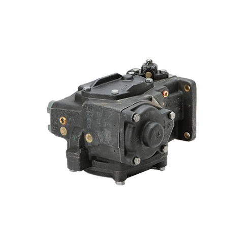
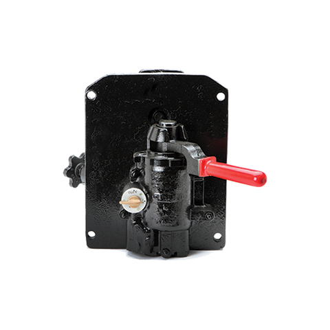
The other valves listed are adjustable for release pressure and have a "pop" action: The pressure differential is not adjustable on these valves. If the valves are operated above their nominal pressure, the set-reset differential increases. If operated at lower pressure, the differential decreases to the point of disappearing about 10-15% below nominal pressure.

Conrader safety valves are designed to protect unfired pressure vessels and systems from over pressure in compressed air and gas applications. The soft seat safety valve (SRV-Series) has an elastomer seal. All Conrader safety valves are designed, manufactured, and certified under our ISO 9001 quality control system to meet the requirements of ASME Boiler and Pressure Vessel Code Section VIII Division 1 and are registered for use in Canada (CRN). Conrader safety valves are also available with the “CE” mark to meet the requirements of the Pressure Equipment Directive of the European Union.
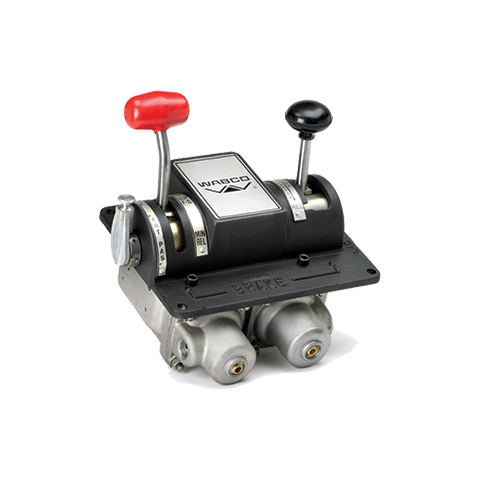
The J-1 Safety Valve installed vertically in the main reservoir system vents pressure at a predetermined setting to atmosphere in order to prevent excessive main reservoir pressure buildup.its used railway.
Kunkle Relief Valve OverviewWhen it comes to industrial and commercial safety and relief valve products, Kunkle’s valve’s catalog is second to none in steam, air, gas, and liquid applications.
Kunkle relief valves range in size from ¼” NPT to 6” flange and are suitable in cryogenic and high temperatures up to 800°F environments at vacuum to 7,500 psig pressure. Kunkle Valve’s code certifications meet several global and national board standards, including ASME Section I, Section IV, and Section VIII, PED, CRN, TU and Chinese, as well as non-code requirements.
Relief Valves for Steam ServiceSteam supplies heat for industrial and chemical processes and also is used to heat buildings, supply mechanical energy, and drive mechanical equipment. Steam moves from the boiler to the end point, then heats by direct heating or indirect heating through a heat exchanger. Kunkle steam relief valves are critical to protecting equipment such as boilers, steam lines, and pressure valves, from being over-pressurized.
Relief Valves for Air ServiceKunkle designs valves for air service, for example for air compressors in mechanical shops and small factories where either low-pressure or high-pressure air is required. NASVI stocks Kunkle relief valves for air service in iron, steel and bronze for a variety of uses.
Relief Valves for Liquid ServiceKunkle also makes valves for liquid service, which provide bypass relief in a variety of applications and liquid types.
More About KunkleKunkle Valve is a renowned pressure relief valve manufacturer. Erastus B. Kunkle invented the safety valve to prevent overpressure in locomotive engines. Kunkle patented it in 1875. Since that time, Kunkle has earned its reputation for high-quality valves, and other equipment manufacturers ship their products with Kunkle’s valves pre-installed.
NASVI has stocked Kunkle safety relief valves since we opened in 1975, so we are confident when we call ourselves Kunkle safety valve experts. Every day we fulfill orders for our customers looking for Kunkle relief valves for steam, air, gas, and liquid applications.
... -start valve with Series MX2 air treatment units without the need for additional connection interfaces. The soft-start valve is positioned upstream of the safety valves, ...
Two hands safety valve, which allows a safety use of two hands pneumatic controls (for example two push-button 3/2 N.C. to a certain distance) excluding false signals in case of push-button ...
The SI2 safety valve prevents the allowed operating pressure from being exceeded by more than 10%. If, after opening, the adjusted response pressure falls ...
... stainless steel full-lift clean service safety valve designed to AD Merkblatt A2 and TRD 421 standards and suitable for pure steam, vapour and inert gases.
Insert style flow control valves are comprised of a precision orifice in parallel with a check valve, combined into a single component. Each is designed for easy installation into metal housings using ...
Press-in style flow control valves are comprised of a precision flow orifice in parallel with a check valve, combined into a single component. Each part is designed for easy installation into plastic ...
If you have been searching for a safety release valve that you can use to reduce short-term pressure surges successfully and diminish the effects of gas leaks, this is the product for you. With a pe of ...
... have been type tested as well. These pressure regulators have safety valves which will slam shut in the event of emergencies, such as the gas reaching too high a pressure level. The valve ...
This product has hydraulically actuated class A gas safety valves to EN 161 used for automatic shut-off. It shuts off when unstimulated for gas and air, or even biologically produced methane. It has AISi ...
The S 104 Safety Shut Off valve is mainly used to avoid any damage to components as well as to avoid too high or too low pressure in the gas train. This could cause high financial losses and/or injured ...
The S50 Safety Shut Off valve is mainly used to avoid any damage to components as well as to avoid too high or too low pressure in the gas train. This could cause high financial losses and/or injured ...
The S100 Safety Shut Off valve is mainly used to avoid any damage to components as well as to avoid too high or too low pressure in the gas train. This could cause high financial losses and/or injured ...
... Pressure Safety Valve + Rupture Disk is protected and may be utilized autonomously as essential security gadgets or in conjunction. There are 3 possible combinations. The first combinations ...
Excavator pipe-rupture valves prevent uncontrolled cylinder movement in the event that a pipe or hose bursts. The ESV valve fulfills all of the requirements of the ISO 8643 and EN 474-5 standards for ...
Material: Body- CF8M; Valve Seat- CF8M Métal Seat, PTFE Soft Seat available Orifice Size: fc"(15mm), 3/4M(20mm), l"(25mm), l1/4,’(32mm)I ltë”(40mm), ...
The Safety valves from ATOS are designed to guarantee protection for application on various devices, especially those that monitor spool position. They are also recommended for hydraulic ...
At almost every show I attend, I ask a few engine owners and operators if they are satisfied with their new-style safety valves. It would be only a small exaggeration to say that I get just two responses. “I have been using a new-style valve for 15 years and I haven’t had any trouble with it” or “They are junk!” I have cleaned up the second response to spare the reader the unpleasant expletives.
As the result of these conversations, I have attempted to understand why there is such a discrepancy between the reactions to modern safety valves. It now appears that there are a few simple steps we can take when purchasing and installing these valves that might improve our satisfaction with the new-style valves, which are the only ones currently available.
To understand the issues involved in the selection of a safety valve, it is necessary to review the history of safety valves used on hand-fired boilers. I am referring to hand-fired boilers rather than historical boilers because the issues are determined by how the boilers are fired, not how they are constructed or how old they are. The requirements for a modern welded boiler made to the American Society of Mechanical Engineers (ASME) code are the same as for a 100-year-old riveted boiler, if both boilers are hand-fired. The requirements for a safety valve for a boiler that is automatically fired are dramatically different.
With automatic firing, the safety valve’s function as defined by Anderson Greenwood Crosby, a manufacturer of modern safety valves, is to protect life and property if all other safety measures fail. A safety valve on a hand-fired boiler, as defined by ASME almost a hundred years ago, is to give notice of the highest pressure permissible and to give alarm that more water or less fuel is needed. (The evolution of the purpose of the safety valve is summarized in “The Purpose of a Safety Valve,” at the end of this article.)
When hand-fired boilers, such as found on traction engines, steam cranes and locomotives disappeared, most of the boilers that remained were automatically fired. The safety valve manufacturers adapted their designs accordingly. The old-style valves with bottom guided, beveled seats were capable of withstanding vibration and operating near their setpoint, and were replaced by smaller top-guided valves with flat seats.
At the same time, steam system designs were adapted so there was no need to operate within 10 percent of the setpoint of the safety valve. Not all old-style valves had beveled seats, but the ones that didn’t were designed much differently from the modern flat-seated valves.
When I speak of a modern-style safety valve, I am referring to a valve shown in the second diagram of this article’s image gallery. An example of an old-style safety valve can also be seen in the image gallery. Changes in the design of safety valves had a dramatic effect on their capacity in pounds of steam per hour. If a boiler built in 1920 required a valve capable of releasing 1,000 pounds of steam per hour at a pressure of 100 pounds per square inch, it would have been equipped with a 2-inch safety valve. Today, 3/4-inch valves are available to release that much steam at that pressure.
The evolution of the safety valve did not end with the development of the modern, flat-seated valve. In the last 20 years, the design of safety valves has continued to evolve.
In 1985, a new-style 3/4-inch valve set at 150 pounds per square inch could have a capacity of 1,497 pounds of steam per hour. In 2002 this same valve could have a capacity of 1,651 pounds of steam per hour.
From 1914 until 1998, the blowdown allowed by the ASME boiler code was 2 to 4 percent of the setpoint. In 1998, this was changed to allow the blowdown to be as high as 6 percent. Beginning with the 2004 ASME code, there is no limit on blowdown. The code has not required that the amount of blowdown be stamped on a safety valve since 1986.
When I asked owners and operators how well they liked their new-style safety valves, I was not aware of the need to ask about the age of the valve. Instead, I would ask about the amount of blowdown. In almost every case, the people who were satisfied had valves that would blowdown 4 percent or less. It appears that this is almost the same as if I had asked the age of the valve. If the valve were purchased prior to 1998, it would have been set for 4 percent blowdown. If purchased after that date, unless specified otherwise, it would have been set for 6 percent. The change from 4 to 6 percent causes a 50 percent increase in the amount the pressure changes in a boiler each time the valve pops. The resulting increase in the flexing of the components of the boiler may be associated with a corresponding increase in seepage at stay bolts and tubes.
When you order a new safety valve, you will need to provide four pieces of information: the setpoint, the capacity in pounds of steam per hour, the blowdown and the requirement that the valve be stamped with the ASME “V” stamp. If you specify the pipe size, you may get a valve with far too much capacity, as I have already explained. To determine the capacity you need, do not use the capacity stamped on the old valve. First, if the valve has been replaced, it might not be the right capacity. Secondly, the capacity stamped on the valve is probably the capacity of the smallest valve available and might be significantly larger than the required capacity.
As I talked to many owners, they would offer other comments regarding their valves. One comment I heard from several owners who were satisfied with the new-style valves was that their valves were larger in pounds per hour than the minimum required by the ASME code. I am not certain as to exactly how the capacity affects the operation of the valve. What I do know is the larger the valve, the more force it takes to raise it off its seat. The force of the steam on the boiler-side of the valve cannot overcome the force of the spring in the safety valve until the pressure in the boiler rises to the setpoint of the valve.
When this happens, the valve pops open. It seems the larger diameter, and thus the greater forces, may result in more stable operation of the valve near its setpoint. There is a concern in the boiler code that safety valves should not be so large that water is drawn out of the boiler. It would seem, because of the relatively small size of portable and traction boilers, the pressure would drop so quickly that little water, if any, would be lost. I have seen boilers where the owners have installed modern safety valves of the same pipe size as the old style valves installed by the factory. The capacity of these valves was far greater than I believe anyone would recommend, but I am not aware that they caused water to be discharged from the boiler. It is important to be careful when sizing a safety valve. I suggest owners talk to each other and share their experiences before making such a decision.
If you would prefer to have a top-discharge safety valve, which looks more authentic, shop around. They are available in a few sizes. You might also want to consider specifying that the valve have a non-metallic seat.
When installing a safety valve, do not install any fitting smaller than the inlet to the valve and do not install any kind of valve between the safety valve and the boiler. Examples of what not to do can be seen in the image gallery. Do not use a pipe wrench on a safety valve, it can damage or destroy the valve.
Once you have carefully selected your safety valve and have installed it on your boiler, it is important to verify the setpoint and the blowdown have been set according to your specifications. The first step in this process is to have the accuracy of your steam gauge checked with a dead-weight gauge tester. If your gauge does not agree with the setpoint of your new safety valve do not assume that the gauge is wrong.
Do not use the lifting lever to lift the valve from its seat until the boiler pressure is up to 75 percent of the setpoint of the valve. If the valve is lifted from its seat at a lower pressure, any dirt or foreign material in the valve might not be blown clear of the seat and could damage the seats when the valve closes.
Because new-style safety valves are not designed to be operated within 10 percent of their setpoint, many owners have elected to install the new valve along with an old-style valve. In doing so, the old style valve operates in the range of 5 to 10 percent below the setpoint of the new valve. With this arrangement, the new valve satisfies the code requirements while the old-style valve performs the function for which it was designed. Two possible arrangements can be seen in the image gallery.
In response to complaints from owners of historical boilers who had recently purchased new safety valves, Dean Jagger, Ohio’s chief boiler inspector, requested that the National Board test valves from the manufacturer to determine if the valves complied with the requirements of the ASME boiler code. As a result of these tests the Ohio Department of Commerce issued a safety notice:
“The State of Ohio Boiler Division has been made aware of the fact that some recently purchased Kunkle safety valves, which were assembled by Allied Industries, have been tested by the National Board Testing Laboratory and found not to be in compliance. The tests indicated that the valves blowdown and setpoint pressure settings were out of tolerance as established by Section I of the ASME Boiler Code.”
This may be an indication that all of the problems with modern safety valves are not entirely the result of design issues, but insufficient oversight of manufacturing and quality control processes may also be a factor. A new valve may be “junk” as has been so often alleged.
The errors found by the National Board Laboratories were significant. One of the valves was stamped 165 psi but popped low at 148.8 psi. Another was stamped 150 psi and popped high at 164.5 psi. On the other three valves the pop was consistent with the setting stamped on the valve. The 2001 edition of the ASME Boiler Code specifies that for pressures from 70 to 300 psi the tolerance, plus or minus from the set pressure, shall not exceed 3 percent of the set pressure. The 165 psi valve popped 9.6 percent below the set pressure stamped on the valve, and the 150 psi valve popped 9.7 percent above the set pressure stamped on the valve.
The blowdowns on all of the valves that were tested were out of tolerance. The 2001 edition of the ASME Boiler Code specifies that for pressures from 67 to 250 psi the blowdown shall not be greater than 6 percent of the set pressure. With such a wide range of variations in both setpoint and blowdown, in a sample of just five valves, it seems reasonable to suspect that even greater variations may exist. The results of the tests are shown in the image gallery.
Complaints about quality problems are not limited to the five valves recently tested by the National Board; for example, an engine owner told me of purchasing a new 1-1/4-inch valve stamped 175 psi. When installed on a traction engine, the valve consistently popped at 185 psi and blew down 15 psi. (A pressure of 11.1 psi equals the allowed 6 percent.) The manufacturer told the owner that the valve had been tested properly prior to shipment but accepted it back. The owner had verified the accuracy of the pressure gauge prior to contacting the manufacturer.
The ASME and National Board procedures for safety valves merely confirm the adequacy of the design of the valve and do not assure the adequacy of production and quality control practices. Each boiler owner and operator must carefully confirm the accuracy of the setpoint and blowdown on every safety valve and not rely on the ASME and National Board stamps as assurances of quality. At this time, I have no reason to believe the monitoring of the ASME and National Board requirements at other valve manufacturers and assemblers is any different than what existed at Kunkle and Allied.
One scenario that concerns me is the owner who installs a new safety valve on his boiler and, seeing that the pop does not coincide with the reading on his 80- or 100-year-old gauge, decides that obviously his gauge must be wrong. This is a conclusion I am sure I would have considered when I first began my study of safety valves.
Incorrect settings of safety valves are more likely to be detected when the valves are used on hand-fired boilers than when used on modern boilers. If the controls on a modern boiler are to limit the pressure to 10 percent or more below the setpoint of the safety valve, the valve can be set as much as 10 percent below its rating and the error might not be apparent. Errors above the setpoint also wouldn’t be obvious even if the boiler were operated up to the setpoint stamped on the valve. Also, incorrect setting of the blowdown would not be apparent until the valve had operated.
1909: “The function of the safety valve is two fold: (A) it gives notice of the highest pressure permissible; (B) it gives alarm that more water or less fuel is needed.”
Today: “A PRV (pressure relief valve) is a safety device intended to protect life and property if all other safety measures fail.” – Anderson Greenwood Crosby, 2001 (safety valve manufactuer)
A reconditioned Ramsbottom type safety valve, cast iron body with 6 stud flange. Suitable for large boilers including stationary and marine types. £ P.O.A.
A reconditioned Ramsbottom type safety valve, cast iron body with 4 stud flange. Suitable for large boilers including stationary and marine types. £ P.O.A.
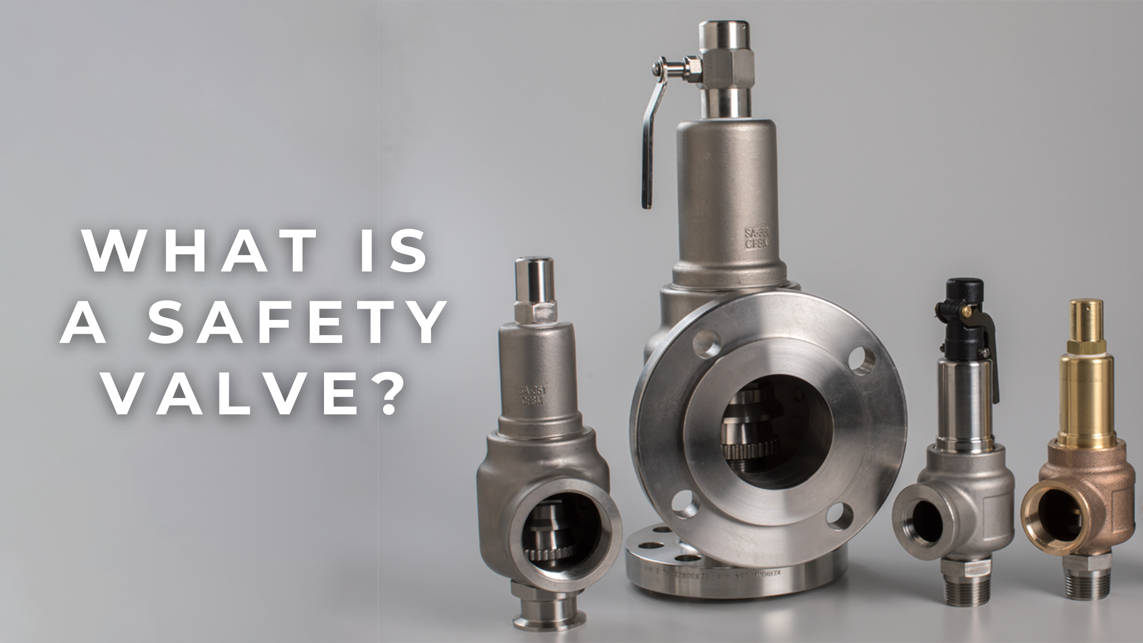
A safety valve is a valve that acts as a fail-safe. An example of safety valve is a pressure relief valve (PRV), which automatically releases a substance from a boiler, pressure vessel, or other system, when the pressure or temperature exceeds preset limits. Pilot-operated relief valves are a specialized type of pressure safety valve. A leak tight, lower cost, single emergency use option would be a rupture disk.
Safety valves were first developed for use on steam boilers during the Industrial Revolution. Early boilers operating without them were prone to explosion unless carefully operated.
Vacuum safety valves (or combined pressure/vacuum safety valves) are used to prevent a tank from collapsing while it is being emptied, or when cold rinse water is used after hot CIP (clean-in-place) or SIP (sterilization-in-place) procedures. When sizing a vacuum safety valve, the calculation method is not defined in any norm, particularly in the hot CIP / cold water scenario, but some manufacturers
The earliest and simplest safety valve was used on a 1679 steam digester and utilized a weight to retain the steam pressure (this design is still commonly used on pressure cookers); however, these were easily tampered with or accidentally released. On the Stockton and Darlington Railway, the safety valve tended to go off when the engine hit a bump in the track. A valve less sensitive to sudden accelerations used a spring to contain the steam pressure, but these (based on a Salter spring balance) could still be screwed down to increase the pressure beyond design limits. This dangerous practice was sometimes used to marginally increase the performance of a steam engine. In 1856, John Ramsbottom invented a tamper-proof spring safety valve that became universal on railways. The Ramsbottom valve consisted of two plug-type valves connected to each other by a spring-laden pivoting arm, with one valve element on either side of the pivot. Any adjustment made to one of valves in an attempt to increase its operating pressure would cause the other valve to be lifted off its seat, regardless of how the adjustment was attempted. The pivot point on the arm was not symmetrically between the valves, so any tightening of the spring would cause one of the valves to lift. Only by removing and disassembling the entire valve assembly could its operating pressure be adjusted, making impromptu "tying down" of the valve by locomotive crews in search of more power impossible. The pivoting arm was commonly extended into a handle shape and fed back into the locomotive cab, allowing crews to "rock" both valves off their seats to confirm they were set and operating correctly.
Safety valves also evolved to protect equipment such as pressure vessels (fired or not) and heat exchangers. The term safety valve should be limited to compressible fluid applications (gas, vapour, or steam).
For liquid-packed vessels, thermal relief valves are generally characterized by the relatively small size of the valve necessary to provide protection from excess pressure caused by thermal expansion. In this case a small valve is adequate because most liquids are nearly incompressible, and so a relatively small amount of fluid discharged through the relief valve will produce a substantial reduction in pressure.
Flow protection is characterized by safety valves that are considerably larger than those mounted for thermal protection. They are generally sized for use in situations where significant quantities of gas or high volumes of liquid must be quickly discharged in order to protect the integrity of the vessel or pipeline. This protection can alternatively be achieved by installing a high integrity pressure protection system (HIPPS).
In the petroleum refining, petrochemical, chemical manufacturing, natural gas processing, power generation, food, drinks, cosmetics and pharmaceuticals industries, the term safety valve is associated with the terms pressure relief valve (PRV), pressure safety valve (PSV) and relief valve.
The generic term is Pressure relief valve (PRV) or pressure safety valve (PSV). PRVs and PSVs are not the same thing, despite what many people think; the difference is that PSVs have a manual lever to open the valve in case of emergency.
Relief valve (RV): an automatic system that is actuated by the static pressure in a liquid-filled vessel. It specifically opens proportionally with increasing pressure
Pilot-operated safety relief valve (POSRV): an automatic system that relieves on remote command from a pilot, to which the static pressure (from equipment to protect) is connected
Low pressure safety valve (LPSV): an automatic system that relieves static pressure on a gas. Used when the difference between the vessel pressure and the ambient atmospheric pressure is small.
Vacuum pressure safety valve (VPSV): an automatic system that relieves static pressure on a gas. Used when the pressure difference between the vessel pressure and the ambient pressure is small, negative and near to atmospheric pressure.
Low and vacuum pressure safety valve (LVPSV): an automatic system that relieves static pressure on a gas. Used when the pressure difference is small, negative or positive and near to atmospheric pressure.
In most countries, industries are legally required to protect pressure vessels and other equipment by using relief valves. Also, in most countries, equipment design codes such as those provided by the ASME, API and other organizations like ISO (ISO 4126) must be complied with. These codes include design standards for relief valves and schedules for periodic inspection and testing after valves have been removed by the company engineer.
Today, the food, drinks, cosmetics, pharmaceuticals and fine chemicals industries call for hygienic safety valves, fully drainable and Cleanable-In-Place. Most are made of stainless steel; the hygienic norms are mainly 3A in the USA and EHEDG in Europe.
The first safety valve was invented by Denis Papin for his steam digester, an early pressure cooker rather than an engine.steelyard" lever a smaller weight was required, also the pressure could easily be regulated by sliding the same weight back and forth along the lever arm. Papin retained the same design for his 1707 steam pump.Greenwich in 1803, one of Trevithick"s high-pressure stationary engines exploded when the boy trained to operate the engine left it to catch eels in the river, without first releasing the safety valve from its working load.
Although the lever safety valve was convenient, it was too sensitive to the motion of a steam locomotive. Early steam locomotives therefore used a simpler arrangement of weights stacked directly upon the valve. This required a smaller valve area, so as to keep the weight manageable, which sometimes proved inadequate to vent the pressure of an unattended boiler, leading to explosions. An even greater hazard was the ease with which such a valve could be tied down, so as to increase the pressure and thus power of the engine, at further risk of explosion.
Although deadweight safety valves had a short lifetime on steam locomotives, they remained in use on stationary boilers for as long as steam power remained.
Weighted valves were sensitive to bouncing from the rough riding of early locomotives. One solution was to use a lightweight spring rather than a weight. This was the invention of Timothy Hackworth on his leaf springs.
These direct-acting spring valves could be adjusted by tightening the nuts retaining the spring. To avoid tampering, they were often shrouded in tall brass casings which also vented the steam away from the locomotive crew.
The Salter coil spring spring balance for weighing, was first made in Britain by around 1770.spring steels to make a powerful but compact spring in one piece. Once again by using the lever mechanism, such a spring balance could be applied to the considerable force of a boiler safety valve.
The spring balance valve also acted as a pressure gauge. This was useful as previous pressure gauges were unwieldy mercury manometers and the Bourdon gauge had yet to be invented.
Paired valves were often adjusted to slightly different pressures too, a small valve as a control measure and the lockable valve made larger and permanently set to a higher pressure, as a safeguard.Sinclair for the Eastern Counties Railway in 1859, had the valve spring with pressure scale behind the dome, facing the cab, and the locked valve ahead of the dome, out of reach of interference.
In 1855, John Ramsbottom, later locomotive superintendent of the LNWR, described a new form of safety valve intended to improve reliability and especially to be tamper-resistant. A pair of plug valves were used, held down by a common spring-loaded lever between them with a single central spring. This lever was characteristically extended rearwards, often reaching into the cab on early locomotives. Rather than discouraging the use of the spring lever by the fireman, Ramsbottom"s valve encouraged this. Rocking the lever freed up the valves alternately and checked that neither was sticking in its seat.
A drawback to the Ramsbottom type was its complexity. Poor maintenance or mis-assembly of the linkage between the spring and the valves could lead to a valve that no longer opened correctly under pressure. The valves could be held against their seats and fail to open or, even worse, to allow the valve to open but insufficiently to vent steam at an adequate rate and so not being an obvious and noticeable fault.Rhymney Railway, even though the boiler was almost new, at only eight months old.
Naylor valves were introduced around 1866. A bellcrank arrangement reduced the strain (percentage extension) of the spring, thus maintaining a more constant force.L&Y & NER.
All of the preceding safety valve designs opened gradually and had a tendency to leak a "feather" of steam as they approached "blowing-off", even though this was below the pressure. When they opened they also did so partially at first and didn"t vent steam quickly until the boiler was well over pressure.
The quick-opening "pop" valve was a solution to this. Their construction was simple: the existing circular plug valve was changed to an inverted "top hat" shape, with an enlarged upper diameter. They fitted into a stepped seat of two matching diameters. When closed, the steam pressure acted only on the crown of the top hat, and was balanced by the spring force. Once the valve opened a little, steam could pass the lower seat and began to act on the larger brim. This greater area overwhelmed the spring force and the valve flew completely open with a "pop". Escaping steam on this larger diameter also held the valve open until pressure had dropped below that at which it originally opened, providing hysteresis.
These valves coincided with a change in firing behaviour. Rather than demonstrating their virility by always showing a feather at the valve, firemen now tried to avoid noisy blowing off, especially around stations or under the large roof of a major station. This was mostly at the behest of stationmasters, but firemen also realised that any blowing off through a pop valve wasted several pounds of boiler pressure; estimated at 20 psi lost and 16 lbs or more of shovelled coal.
Pop valves derived from Adams"s patent design of 1873, with an extended lip. R. L. Ross"s valves were patented in 1902 and 1904. They were more popular in America at first, but widespread from the 1920s on.
Although showy polished brass covers over safety valves had been a feature of steam locomotives since Stephenson"s day, the only railway to maintain this tradition into the era of pop valves was the GWR, with their distinctive tapered brass safety valve bonnets and copper-capped chimneys.
Developments in high-pressure water-tube boilers for marine use placed more demands on safety valves. Valves of greater capacity were required, to vent safely the high steam-generating capacity of these large boilers.Naylor valve) became more critical.distilled feedwater and also a scouring of the valve seats, leading to wear.
High-lift safety valves are direct-loaded spring types, although the spring does not bear directly on the valve, but on a guide-rod valve stem. The valve is beneath the base of the stem, the spring rests on a flange some height above this. The increased space between the valve itself and the spring seat allows the valve to lift higher, further clear of the seat. This gives a steam flow through the valve equivalent to a valve one and a half or twice as large (depending on detail design).
The Cockburn Improved High Lift design has similar features to the Ross pop type. The exhaust steam is partially trapped on its way out and acts on the base of the spring seat, increasing the lift force on the valve and holding the valve further open.
To optimise the flow through a given diameter of valve, the full-bore design is used. This has a servo action, where steam through a narrow control passage is allowed through if it passes a small control valve. This steam is then not exhausted, but is passed to a piston that is used to open the main valve.
There are safety valves known as PSV"s and can be connected to pressure gauges (usually with a 1/2" BSP fitting). These allow a resistance of pressure to be applied to limit the pressure forced on the gauge tube, resulting in prevention of over pressurisation. the matter that has been injected into the gauge, if over pressurised, will be diverted through a pipe in the safety valve, and shall be driven away from the gauge.
There is a wide range of safety valves having many different applications and performance criteria in different areas. In addition, national standards are set for many kinds of safety valves.
Safety valves are required on water heaters, where they prevent disaster in certain configurations in the event that a thermostat should fail. Such a valve is sometimes referred to as a "T&P valve" (Temperature and Pressure valve). There are still occasional, spectacular failures of older water heaters that lack this equipment. Houses can be leveled by the force of the blast.
Pressure cookers usually have two safety valves to prevent explosions. On older designs, one is a nozzle upon which a weight sits. The other is a sealed rubber grommet which is ejected in a controlled explosion if the first valve gets blocked. On newer generation pressure cookers, if the steam vent gets blocked, a safety spring will eject excess pressure and if that fails, the gasket will expand and release excess pressure downwards between the lid and the pan. Also, newer generation pressure cookers have a safety interlock which locks the lid when internal pressure exceeds atmospheric pressure, to prevent accidents from a sudden release of very hot steam, food and liquid, which would happen if the lid were to be removed when the pan is still slightly pressurised inside (however, the lid will be very hard or impossible to open when the pot is still pressurised).


 8613371530291