
oil well safety valve in stock
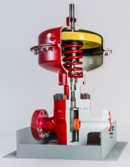
Surface-controlled subsurface safety valves (SCSSVs) are critical components of well completions, preventing uncontrolled flow in the case of catastrophic damage to wellhead equipment. Fail-safe closure must be certain to ensure proper security of the well. However, this is not the only function in which it must be reliable—the valve must remain open to produce the well. Schlumberger surface controlled subsurface safety valves exceed all ISO 10432 and API Spec 14A requirements for pressure integrity, leakage acceptance criteria, and slam closure.
Through decades of innovation and experience, Schlumberger safety valve flapper systems are proven robust and reliable. The multizone dynamic seal technology for hydraulic actuation of subsurface safety valves is a further improvement in reliability performance when compared with traditional seal systems in the industry.
The multizone seal technology was developed and proved with exhaustive verification and validation of reliability, longevity, and performance. The validation methodology utilized a unique sapphire crystal bore, enabling the design team to view the seal’s dynamic and static performance in real time while simulating wellbore pressure and temperature conditions.
The multizone seal technology is currently available in the GeoGuard high-performance deepwater safety valves, which is validated to API Spec 14A V1 and V1-H.
GEM-Valve system enables remediation without relinquishing control of subsurface safety shut-in equipment via wireless surface control of the valve, allowing reliable and regulatory compliant production of oil and gas wells.
Installed as a temporary safety valve solution, the system eliminates production deferral while workover intervention planning and sourcing activities take place. Installed as a permanent solution, it eliminates significant workover repair and recompletion costs, which might not be justifiable for old producing wells in mature fields.

Safety valves are designed to automatically shut in the flow of a well in the event surface controls fail or surface equipment becomes damaged. They are classified according to the location from which they are controlled – surface or subsurface. In this article, subsurface safety valve types, operating systems, working principle, setting depth, and selection process are presented.
It is advisable, and in most cases mandatory, to have a secondary means of closure for all wells capable of natural flow to the surface. The installation on of a sub-surface safety valve (SSSV) will provide this emergency closure capability.
Operating systems may be either remotely operated on a fail-safe principle from surface (SCSSV) actuated from a control panel located on surface, or will be a subsurface controlled (SSCSV), designed to close automatically when a predetermined flow condition occurs in the well (actuated by the pressure differential/flow velocity across the valve).
In case of SCSSV, a 1/4″ inch stainless steel control line is attached to the outside of the tubing string and installed when the tubing is installed. Depending on the wellhead pressure, it may be necessary to keep as much as 4000 to 5000 psi on the control line to keep the valve open.
The differential type subsurface controlled subsurface safety valve senses pressure drop across a flow bean. There are several variations of the differential type SSCSV. Although they employ different sealing devices, such as a flapper or ball, they all are controlled with a flow bean and spring tension.
As shown in the following video, when hydraulic pressure is applied down a control line, the hydraulic pressure forces a sleeve within the valve to slide downwards. This movement compresses a large spring and pushes the flapper (in case of flapper type SCSSV) or the ball (in case of ball type SCSSV) downwards to open the valve. When hydraulic pressure is removed, the spring pushes the sleeve back up and causes the flapper (or the ball) to shut. In this way, it is failsafe and will isolate the wellbore in the event of a loss of the wellhead.
The location of the downhole safety valve within the completion is a precisely determined parameter intended to optimise safety. There are arguments against it either being too high or too low in the well and so the final depth is a compromise of all factors. MMS regulations state that the valve must be placed no less than 100′ below the mudline.

Maintaining safe operating conditions can be challenging in deep-set or deepwater, high-pressure/high-temperature (HP/HT) wells. The REACH™ subsurface safety valve from Baker Hughes provides an answer, with fail-safe operation in a wide range of deep-set completions that require low operating pressures due to control system limitations.
REACH safety valves are designed to provide reliable sealing in deep, HP/HT wells. They can be set up to 20,000 ft (6,096 m) below sea level and withstand temperatures up to 400°F (205°C) and pressures up to 20,000 psi (1,379 bar).
REACH safety valves are V1 validated and have undergone the stringent prototype testing per API SPEC 14A, Specification for Subsurface Safety Valve Equipment, Twelfth Edition. Our safety valve specialists have continuously modified the design to accommodate the new V1 validation specifications while progressively exceeding the requirements set forth by API.
REACH valves rely on field-proven, heavy-sprung closure technology to ensure fail-safe-closed operation. Because tubing pressure is isolated from the control system, the valve can open at much lower operating pressures, reducing the cost of umbilicals in some applications.
The valve’s unique activation system requires lower valve operating pressures than previous safety valve designs by eliminating the need to overcome tubing pressure, making the valve ideal for applications with opening pressure limitations including: subsea completions, high-pressure wells, and fields where the rig site and other control facilities may have supply pressure limitations.
REACH valves incorporate several proven features from other safety valve designs, including flapper closure technology, RBT housing thread technology, dynamic seal technology, and debris exclusion geometries—all of which help deliver integrated functionality and dependability.
To ensure long term reliability, the valve is also offered with a reinforced dynamic seal configuration, upgraded dynamic seal materials, internal alignment enhancements, and an enhanced scraper ring to minimize debris. Because the REACH valve does not utilize gas springs, the operating seals and gland do not experience pressure reversals, making them ideal for your critical deepwater HP/HT applications

Maintaining fluid control and well protection is critical in your shallow depth well operations. The SelecT™ subsurface safety valve from Baker Hughes addresses the unique challenges that shallow set safety valves (typically <1,000 ft) endure.
The tubing-retrievable SelecT valve includes an ultra-strong power spring that delivers the high closing forces needed to reliably and consistently close the valve in the presence of paraffin and other produced solids.
The SelecT is engineered to avoid failures due to wireline damage during downhole interventions. The valve’s advanced flapper design prevents damage and ensures that all seal surfaces are protected from wireline contact—even during accidental closure of the valve during wireline operations.
Ensure greater seal integrity with the SelecT valve’s patented advances that include thru-the-flapper self-equalizing system. And the radial punch control fluid communication system eliminates accidental communication associated with linear shifting sleeves.

A downhole safety valve refers to a component on an oil and gas well, which acts as a failsafe to prevent the uncontrolled release of reservoir fluids in the event of a worst-case-scenario surface disaster. It is almost always installed as a vital component on the completion.
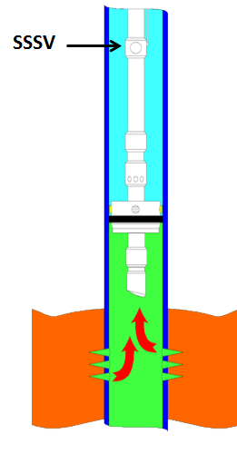
These valves are commonly uni-directional flapper valves which open downwards such that the flow of wellbore fluids tries to push it shut, while pressure from the surface pushes it open. This means that when closed, it will isolate the reservoir fluids from the surface.
Most downhole safety valves are controlled hydraulically from the surface, meaning they are opened using a hydraulic connection linked directly to a well control panel. When hydraulic pressure is applied down a control line, the hydraulic pressure forces a sleeve within the valve to slide downwards. This movement compresses a large spring and pushes the flapper downwards to open the valve. When hydraulic pressure is removed, the spring pushes the sleeve back up and causes the flapper to shut. In this way, it is failsafe and will isolate the wellbore in the event of a loss of the wellhead. The full designation for a typical valve is "tubing retrievable, surface controlled, subsurface safety valve", abbreviated to TR-SCSSV.
The location of the downhole safety valve within the completion is a precisely determined parameter intended to optimise safety. There are arguments against it either being too high or too low in the well and so the final depth is a compromise of all factors. MMS regulations state that the valve must be placed no less than 30 m (100 ft) below the mudline.
The further down the well the DHSV is located, the greater the potential inventory of hydrocarbons above it when closed. This means that in the event of loss of containment at surface, there is more fluid to be spilled causing environmental damage, or in the worst case, more fuel for a fire. Therefore, placing the valve higher limits this hazard.
Another reason relates to the hydraulic control line. Hydraulic pressure is required to keep the valve open as part of the failsafe design. However, if the valve is too far down the well, then the weight of the hydraulic fluid alone may apply sufficient pressure to keep the valve open, even with the loss of surface pressurisation.
As part of the role of the DHSV to isolate the surface from wellbore fluids, it is necessary for the valve to be positioned away from the well where it could potentially come to harm. This implies that it must be placed subsurface in all circumstances, i.e. in offshore wells, not above the seabed. There is also the risk of cratering in the event of a catastrophic loss of the topside facility. The valve is specifically placed below the maximum depth where cratering is expected to be a risk.
If there is a risk of methane hydrate (clathrate) plugs forming as the pressure changes through the valve due to Joule–Thomson cooling, then this is a reason to keep it low, where the rock is warmer than an appropriately-calculated temperature.
Most downhole safety valves installed as part of the completion design are classed as "tubing retrievable". This means that they are installed as a component of the completion string and run in during completion. Retrieving the valve, should it malfunction, requires a workover. The full name for this most common type of downhole safety valve is a Tubing Retrievable Surface Controlled Sub-Surface Valve, shortened in completion diagrams to TRSCSSV.
If a tubing retrievable valve fails, rather than go to the expense of a workover, a "wireline retrievable" valve may be used instead. This type of valve can fit inside the production tubing and is deployed on wireline after the old valve has been straddled open.
The importance of DHSVs is undisputed. Graphic images of oil wells in Kuwait on fire after the First Gulf War after their wellheads were removed, demonstrate the perils of not using the components (at the time, they were deemed unnecessary because they were onshore wells). It is, however, not a direct legal requirement in many places. In the United Kingdom, no law mandates the use of DHSVs. However, the 1974 Health & Safety at Work Act requires that measures are taken to ensure that the uncontrolled release of wellbore fluids is prevented even in the worst case. The brilliance of the act is that it does not issue prescriptive guideline for how to achieve the goal of health and safety, but merely sets out the requirement that the goal be achieved. It is up to the oil companies to decide how to achieve it and DHSVs are an important component of that decision. As such, although not a legal requirement, it is company policy for many operators in the UKCS.
While the DHSV isolates the production tubing, a loss of integrity could allow wellbore fluid to bypass the valve and escape to surface through the annulus. For wells using gas lift, it may be a requirement to install a safety valve in the "A" annulus of the well to ensure that the surface is protected from a loss of annulus containment. However, these valves are not as common and they are not necessarily installed at the same position in the well, meaning it is possible that fluids could snake their way around the valves to surface.
Device whose design function is to prevent uncontrolled well flow when closed. NOTE SSSVs can be installed and retrieved by wireline or pump-down methods (wireline retrievable) or be an integral part of the tubing string (tubing-retrievable).
As long ago as 1936, accelerated drilling of high pressure oil and gas wells in inland waters near town sites and other dangerous or isolated places required a device to protect wells from uncontrolled flow caused by accident or other damage to surface equipment. To meet this need, many types of safety valves were built and tried, most of them being of the velocity-operated type. These valves were designed to operate by increased velocity, or by the pressure differential across the valve caused by the increased velocity of flow, or by a drop in pressure to a predetermined value, caused by the rupture of some part of the well equipment on the surface. The velocity operated valve is subjected to inherent variables of flowing wells which made it difficult for average operating people to calculate and set the closing rate accurately.
While the velocity-operated valve is suitable for flowing wells producing at reduced rates, it is less suitable in areas where large volumes of flow are permitted. In wells produced at rates at or close to their potential, it is hard to predetermine spring settings to guarantee closure in an emergency.
With the rapid extension of the offshore fields into the shipping lanes of such areas as Lake Maracaibo and the Gulf of Mexico, it became apparent that a safety device should be developed which would not have the disadvantages of the velocity-operated valve.
In Venezuela, work was started on a surface controlled subsurface safety valve which would not be dependent upon the velocity off low to close the valve. As a result of this effort} the ball valve came into being. It is used in many of the oil wells in Lake Maracaibo, Venezuela.
Production sustainability from oil and gas wells could be an uphill task when there is a need to constantly monitor Subsurface safety valves for optimal functionality. It"s always a standard practice that surface safety valves are tested on specific periods safe enough to ensure well"s safety is not compromised. Surface controlled subsurface safety valves are also tested with same objective.
Many Production Engineers are ignorant of the fact that the subsurface safety valve affect well productivity through drop in hydrostatic pressure across valve for Surface Controlled Subsurface Safety Valve (SCSSV) and the Sub-Surface Controlled Subsurface Safety Valves (SSCSV) additionally causes drop in fluid flow across valves in the process of sensing fluid velocity across valve.
In this Paper, A case by case analysis was performed on the various sub-surface safety valves for producing wells with the view of minimizing friction to flow of well fluids which affects performance which in turn minimizes production restriction. Efficiency of different type of subsurface safety valves where evaluated and compared and business cases where made on the most attractive option.
Periodic testing or inspection of valves was analyzed, and best routine testing time proffered with reasons to wells performance. The advantages and disadvantage of different valve options were also discussed to recommend a workable valve option for Uninterrupted well flow. Flow assurance and flow stability considerations were also made to ensure no unwanted valve closure occurs.
A Stable and uninterrupted production was realized for five wells using this analytical method and the total productivity increase was about 1,200 BOPD for the five wells. Addressed wax blockage valve/sticky flapper problems to enable the SCSSV four wells function. The SSCSV of the last well caused flow assurance challenges which was addressed by surface choke bean optimization.
Subsurface safety valves (SSSVs), which are standard and often statutorily required in the oil and gas industry for upper completions, were first developed in the late 1930s. Operators sought to drill more high-pressure wells, often near populated areas or, conversely, offshore or very isolated areas, making the need for a device to protect the wells from uncontrolled flow increasingly apparent. The need was made even more urgent by the fact that the uncontrolled flow could be caused by accident or by damage to the surface equipment, which at the time was quite common.
By the 1970s three companies had established themselves as industry leaders as SSSV suppliers in the field: Otis Engineering (now Halliburton), Baker Hughes (now Baker Hughes, a GE company) and Camco Products and Services (now Schlumberger). Implementation of SSSVs grew, but it was not until the Piper Alpha incident of the late 1980s that regulations truly shifted. The explosion on Piper Alpha and resulting oil and gas fires that destroyed the platform served as the impetus for global regulatory mandates that SSSVs be deployed in offshore wells.
The watchword for the 21st century oil industry has been reliability, as offshore, deepwater workovers in many wells cost tens of millions of dollars. As such, reliability became the primary focus and mission of the engineering team at Tejas Research & Engineering as it moved to design and deliver reliable, high-performing products. In the late 2000s the energy industry and governments worldwide revisited the use of SSSV deployment requirements, which had not seen much change since the Piper Alpha incident more than two decades prior. The consensus was that when reliable SSSVs are present, a blowout and oil spill are virtually impossible. Therefore, many governments, such as the EU, now require SSSVs in all wells—even those on land.
Modern developments in SSSV design have sought to address the industry’s challenges and the issues that arise in more complex reservoirs and harsher downhole environments through additional testing and research to optimize the valves’ technical specifications. While the basic functionality of the valves has not changed for some time, the standard to which the valves are engineered and manufactured is now shifting, thanks in part to a new partnership between Tejas Research & Engineering and National Oilwell Varco (NOV). It is a partnership bolstered by Tejas’ involvement on the American Petroleum Institute’s (API) 14A standards subcommittee.
NOV has built its portfolio of completion and production products and technologies since the company’s acquisition of Trican Well Service’s completion tools division in mid-2016. As the breadth of NOV’s completions business expanded to include multistage fracturing and multizone completions, among other disciplines, it became clear that a missing link for upper completions was SSSVs. The company partnered with Tejas Research & Engineering to commercialize a line of SSSVs representing a new industry standard in design and reliability.
Tejas Research & Engineering sprang from the Camco tradition that pioneered many pivotal developments in SSSV design. The R&D and engineering for safety valve products are conducted in Tejas’ HP/HT facility in The Woodlands, Texas, where SSSVs with pressure requirements of 25,000 psi and 260 C (500 F) are designed, tested, qualified and produced.
Tejas’ model TRSV(E) SSSVs are tubing-retrievable, surface- controlled, normally closed devices installed in oil and gas wells to control tubing fl ow. Metal-to-metal seals are used in 100% of Tejas’ tubing-retrievable product line, which has products that are rated to 10,000 psig and are suitable for temperatures up to 176 C (349 F) at moderate setting depths. Higher temperature/pressure/setting depths/slimline diameters are available for custom order. The TRSSSV series are API-14A V1 certified and adaptable to any standard or premium tubing thread. The system features a large fullbore, where the inside diameter (ID) is equivalent or greater tubing than the tubing ID to which the SSSV is attached. Additionally, it has either flat flappers (2⅜ in. to 3½ in.) or curved flappers (4½ in. to 7 in.) and a single rod piston featuring nonelastomeric dynamic seals. The TRSSSV is available in either equalizing or nonequalizing trims. The valve is controlled hydraulically with a ¼-in. control line in the well’s annulus, enabling valve closure during an emergency shutdown.
The new safety valve builds upon lessons learned in valve design over Tejas Research & Engineering’s entire history. Previous valves have achieved significant milestones— including one design that has more than 8,000 valves in use without a single failure or degradation in performance. Completions have evolved since those early designs, and new valves need to withstand significantly higher temperatures, working pressures and setting depths as well as accommodate different diameters. The new valve product line meets the rigorous quality standards outlined in API Specification 14A and tested beyond the specifications in Revision 12, including Annex H, which specifically addresses the verification and validation requirements for use in HP/HT environments.
An evolution in safety valve standards means the industry can be more confident that well control incidents will not occur. As regulations continue to change and become stricter, it is imperative that safety valves maintain their rigorous quality and durability while being able to handle even more challenging well environments.
Searching for tools to control the flow of your piping system? Explore one of the largest featured collections of products and discover a range of wholesale oil well safety valve on Alibaba.com. When you search for oil well safety valve and related items, you will be able to find many types of oil well safety valve varying in size, shape, use, and quality, all at prices in which are highly reasonable!
There are many uses of valves - mainly controlling the flow of fluids and pressure. Some examples include regulating water for irrigation, industrial uses for controlling processes, and residential piping systems. Magnetic valves like those using the solenoid, are often used in a range of industrial processes. Whereas backflow preventers are often used in residential and commercial buildings to ensure the safety and hygiene of the water supplies. Whether you are designing a regulation system for irrigation or merely looking for a new replacement, you will be able to find whatever type of oil well safety valve that you need. Our products vary from check valves to pressure reducing valves, ball valves, butterfly valves, thermostatic mixing valves, and a lot more.

To protect the surface facilities in case of emergency, the wellbore is isolated from surface facilities using a subsurface safety valve (SSSV). Hence such a safety valve needs to be fail safe in order to isolate well bore in any kind of system failure or damage to surface production, control and safety facilities.
A subsurface safety valve is typically a uni-directional flapper valve, directed in such a way that the flappers open downwards when pressure is applied from an upward direction. The flapper can only open in the downward direction. So even if high pressure is applied by the well fluids from a downward direction, a safety valve can remain closed. This makes a subsurface safety valve fail-safe. To open the valve, hydraulic signal is sent from the surface well control panel. This hydraulic pressure is responsible for keeping the flappers of SSSV open and loss of hydraulic pressure result in closing of the valve. Thus wellbore can be isolated in case of system failure or damage to the surface facilities.

The tubing-retrievable subsurface safety valve (SSSV) provides well protection against pressure drop and system failure in wireline and thru-tubing operations. This retrievable safety valve is controlled from the surface with a hydraulic control line. The valve connects to the tubing string and remains open if adequate pressure is maintained. If pressure drops below the threshold (as occurs in the beginning stages of losing well control), the valve closes. This creates a barrier in the tubing to prevent fluids from rushing up the tubing.
The tubing-retrievable SSSV uses a fail-safe design to prevent the release of unwanted fluids during well completion. This is a critical HSE and well-control requirement on all wells capable of natural flow.


 8613371530291