
oil well safety valve free sample

Surface-controlled subsurface safety valves (SCSSVs) are critical components of well completions, preventing uncontrolled flow in the case of catastrophic damage to wellhead equipment. Fail-safe closure must be certain to ensure proper security of the well. However, this is not the only function in which it must be reliable—the valve must remain open to produce the well. Schlumberger surface controlled subsurface safety valves exceed all ISO 10432 and API Spec 14A requirements for pressure integrity, leakage acceptance criteria, and slam closure.
Through decades of innovation and experience, Schlumberger safety valve flapper systems are proven robust and reliable. The multizone dynamic seal technology for hydraulic actuation of subsurface safety valves is a further improvement in reliability performance when compared with traditional seal systems in the industry.
The multizone seal technology was developed and proved with exhaustive verification and validation of reliability, longevity, and performance. The validation methodology utilized a unique sapphire crystal bore, enabling the design team to view the seal’s dynamic and static performance in real time while simulating wellbore pressure and temperature conditions.
The multizone seal technology is currently available in the GeoGuard high-performance deepwater safety valves, which is validated to API Spec 14A V1 and V1-H.
Our downhole safety valves provide your testing operations with fail-safe sustained control downhole in the event of an emergency or to facilitate test procedures.
Pressure relief valve is related to Microchek.com. We offer competitive pricing and reliability because we are the manufacture. Parts are molded and assembled in the U.S. The Microchek system incorporates this cartridge and a wide selection of end pieces to accommodate most connection requirements. The Microchek valve is a cartridge check valve incorporating an innovative guided poppet design. Relief valves are used to hold a fluid circuit or reservoir at a positive or negative pressure. We can select valves that fall into a specific cracking pressure range if needed. The Microchek valve has a low pressure drop and can be specified with a wide variety of cracking pressures.
The Microchek valve is a cartridge check valve incorporating an innovative guided poppet design. Relief valves are used to hold a fluid circuit or reservoir at a positive or negative pressure. We want the opportunity to help you solve your flow control applications and we can build special configurations.

This invention relates to surface controlled subsurface safety valves used in the oil and gas industry and particularly including a mechanism for temporarily locking the valves open and for remedial cycling of the valves.
It is common practice to complete oil and gas producing wells with systems including a subsurface safety valve controlled from the well surface to shut off fluid flow in the well tubing string. Generally such a valve is controlled in response to control fluid pressure conducted to the valve from a remote location at the well surface via a small diameter conduit permitting the well to be selectively shut in as well conditions require. However, the present invention is not limited to use with safety valves that respond only to fluid pressure signals. The surface controller is typically equipped to respond to emergency conditions such as fire, broken flow lines, oil spills, etc. Frequently it is necessary to conduct well servicing operations through a subsurface safety valve. When a safety valve malfunctions, it may be necessary to install a second safety valve. In any event, it may be desirable to either permanently or temporarily lock the safety valve open. For example, if the well servicing operation requires extending a wireline tool string through the subsurface safety valve, it is preferable to use a lock open system which is not dependent upon control fluid pressure from the well surface. When operations are being carried out through an open subsurface safety valve such as pressure and temperature testing, it can be extremely expensive and time-consuming for a valve to accidentally close on the supporting wireline causing damage to the wireline and sensing apparatus supported therefrom. Additional well servicing procedures are required to retrieve the damaged equipment. Subsurface safety valves including both a permanent and a temporary lock open mechanism are shown in the following U.S. Pat. Nos. 3,786,865; 3,882,935; 4,344,602; 4,356,867; and 4,449,587. The present invention particularly relates to a subsurface safety valve of the type shown in U.S. Pat. Nos. 3,786,865 and 4,449,587 employing a temporary lockout arrangement for the flapper type of valve closure included in the subsurface safety valves. The previously listed patents are incorporated by reference for all purposes in this application. Copending U.S. patent application Ser. No. 06/658,275 filed on Oct. 5, 1984 now U.S. Pat. No. 4,624,315 is directed towards solving some of the same problems as the present invention.
The present invention relates primarily to tubing retrievable flapper type safety valves having a housing connectable with a well tubing string and a bore therethrough for communicating well fluid flow with the tubing string, a flapper valve mounted in the housing for movement between a first open position and a second closed position, and an operator tube in the housing to shift the flapper valve between its second position and its first position. The operator tube normally moves in response to a control signal from the well surface, but a shifting tool can releasably engage the operator tube for movement independent of the control signal. A lockout sleeve may be mounted in the housing in tandem with the operator tube for movement between a first position engaging and holding the flapper valve open and a second position of disengagement from the flapper valve. A shifting tool is also provided having selective locating keys and latch dogs for releasably coupling with the operator tube and the lockout sleeve, respectively. An alternative embodiment of the present invention can be used with any type of surface controlled subsurface safety valve to cycle the valve closure mechanism if it is stuck or the control signal is inoperative.
It is a principal object of the present invention to provide a subsurface safety valve for use in oil and gas wells including a lockout sleeve for temporarily holding or locking open the safety valve during well servicing operations.
It is another object of the invention to provide a subsurface safety valve having an operator tube and a lockout sleeve with a shifting tool latching the operator tube and sleeve together during movement of the sleeve to a position in which the sleeve holds the valve closure mechanism of the subsurface safety valve open.
It is another object of the invention to provide a subsurface safety valve having a lockout sleeve which has a smooth, uniform inside diameter to minimize the possibility of other well tools accidentially shifting the lockout sleeve.
It is another object of the invention to provide a subsurface safety valve including a temporary lockout sleeve wherein the shifting tool does not engage the inside diameter of the temporary lockout sleeve to move the sleeve.
It is another object of the invention to provide a subsurface safety valve including an operator tube which may be operated by an alternative shifting tool to check the proper functioning and full travel of the operator tube of the safety valve.
Still another object of the invention is to provide a subsurface safety valve including a modified operator tube and an alternative shifting tool which may be used to move the operator tube of the valve to free the operator tube or valve closure means when jammed by sand or other well debris.
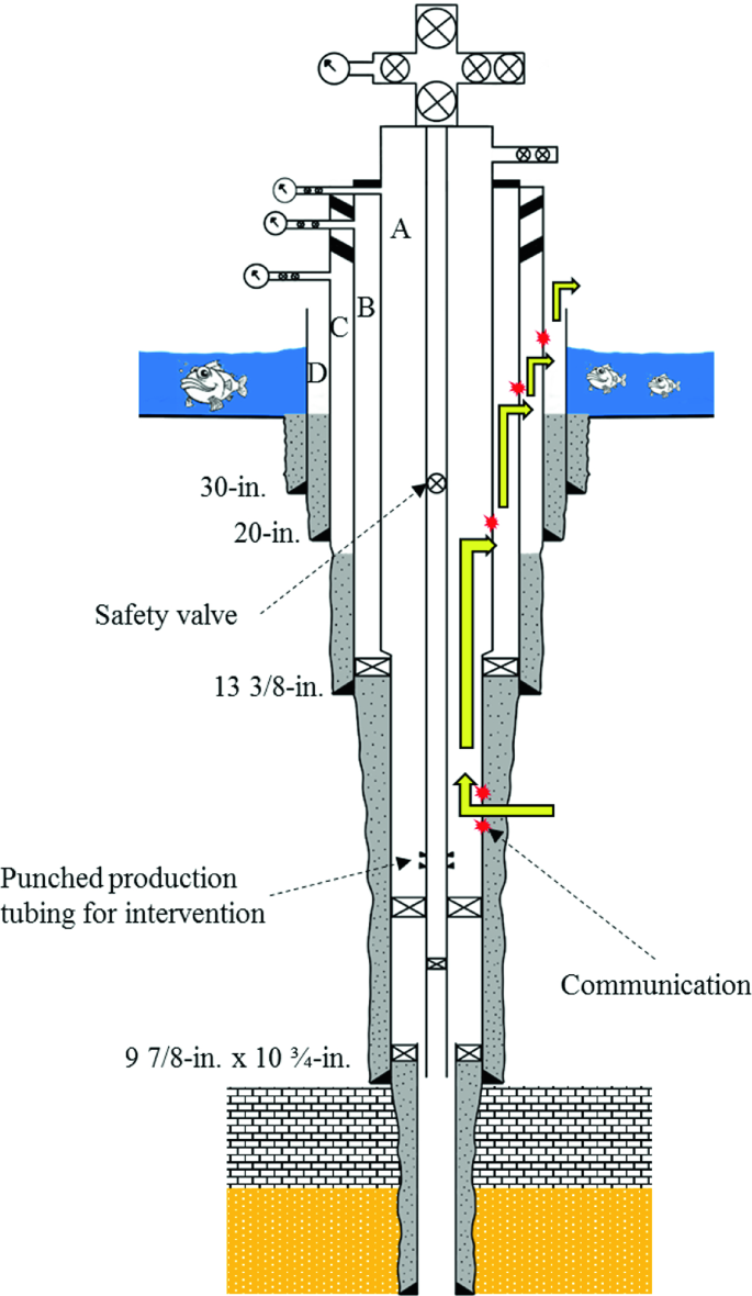
FIG. 1 is a schematic view in section and elevation of a typical well completion including a tubing retrievable subsurface safety valve with a flapper type valve closure means.
FIGS. 2A, 2B, 2C, and 2D taken together form a longitudinal view, in section and elevation with portions broken away, of a subsurface safety valve and lockout sleeve incorporating the present invention showing the safety valve in its open position.
FIGS. 5A, 5B, and 5C taken together form a longitudinal view in section and elevation showing the safety valve of FIGS. 2A-D with the valve closure means open, the lockout sleeve of the safety valve in its inoperative position, and the shifting tool of FIG. 3 engaged therewith.
FIGS. 6A, 6B, and 6C taken together form a view similar to FIGS. 5A, 5B, and 5C showing the shifting tool and the safety valve after shifting the lockout sleeve to hold open the valve closure means.
FIGS. 7A, 7B, and 7C taken together form a view similar to FIGS. 6A-C showing the shifting tool released from the operator tube in the safety valve after shifting the lockout sleeve to hold open the valve closure means.
Referring to FIG. 1, well completion 20 includes casing string 28 extending from the well surface to a hydrocarbon producing formation (not shown). Tubing string 21 is concentrically disposed within casing 28 and extends from wellhead 23 through production packer 22 which seals between tubing string 21 and casing 28. Packer 22 directs formation fluids such as oil, gas, water, and the like into tubing string 21 from perforations (not shown) in casing 28 which admit formation fluids into the well bore. Flow control valves 24a and 24b at the well surface control fluid flow from tubing string 21. Wellhead cap 27 is provided on wellhead 23 to permit servicing well 20 via tubing string 21 by wireline techniques which include the installation and removal of various flow control devices such as valves from within tubing string 21. Other well servicing operations which may be carried out through tubing string 21 are bottom hole temperature and pressure surveys.
Surface controlled subsurface safety valve 30 embodying the features of the invention is installed in well 20 as a part of tubing string 21 to control fluid flow to the well surface via tubing string 21 from a downhole location. Safety valve 30 is operated by control fluid conducted from hydraulic manifold 25 at the well surface via control line conduit 26 which directs the control fluid signal to safety valve 30. Hydraulic manifold 25 generally includes pumps, a fluid reservoir, accumulators, and control valves for the purpose of providing control fluid pressure signals for holding valve 30 open or allowing valve 30 to close when desired. Manifold 25 also includes apparatus which functions in response to temperature, surface line leaks, and other emergency conditions under which well 20 should be shut in.
Safety valve 30 includes flapper type valve closure means 31 mounted by hinge 34 for swinging between a closed position schematically represented in FIG. 1 and an open position which permits fluid flow in tubing string 21. When a predetermined pressure signal is applied to safety valve 30 through control line 26 from manifold 25, valve closure means 31 is maintained in its first or open position. When the control pressure signal is released, valve 30 is allowed to move to its second or closed position. In accordance with the invention, lockout sleeve 50 is provided in valve 30 for movement between a first position which holds valve closure means 31 open and a second position in which valve closure means 31 is free to open or close. With flapper 31 restrained open by lockout sleeve 50, various well servicing operations may be conducted without fear of inadvertent closure of valve 30 which can be damaging to the servicing equipment.
Details of the construction of the preferred form of valve 30 and lockout sleeve 50 are shown in FIGS. 2A-D. Shifting tool 70 for operating lockout sleeve 50 illustrated in FIGS. 3A-B will also be described in detail. Subsurface safety valve 30 has housing means 60 formed by a top sub 61a, a bottom sub 61b, and interconnected housing subassemblies 62, 63, 64, 65, and 66 which are suitably interconnected by threaded joints as illustrated. Housing means 60 can be generally described as a long thick walled cylinder with longitudinal bore 67 extending therethrough. The top and bottom subs 61a and 61b may be internally or externally threaded to provide means on opposite ends of housing means 60 for connection with tubing string 21 as represented in FIG. 1. Top sub 61a includes locking grooves 68 machined on its inside diameter. Locking grooves 68 provide means for installing a secondary or retrievable safety valve (not shown) within longitudinal bore 67 if safety valve 30 should become inoperative. The secondary valve may be designed to operate in response to the same control signal as safety valve 30 or may be designed to respond directly to changing well conditions.
Housing subassembly 62 has threaded connection 29 to allow attaching control line 26 to safety valve 30. Control fluid pressure signals are communicated from the well surface via control line 26, threaded connection 29, passageway 81, and opening 82 to longitudinal bore 67. Cylinder 83 is positioned within longitudinal bore 67 adjacent to opening 82. During normal operation of safety valve 30, control fluid pressure signals are directed to operator tube 40 via annular passageway 84 formed between the inside diameter of housing subassembly 62 and the outside diameter of cylinder 83.
Permanent lockout sleeve 80 is slidably disposed within longitudinal bore 67. Permanent lockout sleeve 80 is sized to fit concentrically within cylinder 83. During normal operation of safety valve 30, knockout plug 85 holds permanent lockout sleeve 80 in its inactive position shown in FIG. 2A. If safety valve 30 should become inoperative, profile 86 on the inside diameter of permanent lockout sleeve 80 can be engaged by a suitable shifting tool (not shown) to force sleeve 80 into abutting contact with operator tube 40 and to open safety valve 30. Movement of sleeve 80 causes knockout plug 85 to shear, allowing communication of control fluid pressure signals therethrough. Snap ring 87 is carried by housing subassembly 62 within longitudinal bore 67 to lock sleeve 80 in place after it has moved. Matching teeth 88 are carried on the outside diameter of sleeve 80 and the inside diameter of snap ring 87. The use of locking recesses 68, permanent locking sleeve 80, and associated components to install a secondary safety valve within longitudinal bore 67 is well known in the art.
Operator tube 40 is slidably disposed within longitudinal bore 67 to shift valve closure means 31 from its second, closed position to its first, open position as shown in FIG. 2C. For ease of manufacture and assembly, operator tube 40 is constructed from two generally hollow, cylindrical subassemblies designated 40a and 40b. Subassemblies 40a and 40b are joined together by threaded connection 41. Piston seal means 42 is carried on the exterior of operator tube 40 to form a sliding fluid barrier with the inside diameter of housing subassembly 63 adjacent thereto. Seal means 43 is carried by cylinder 83 to form a fluid barrier with the exterior of operator tube 40. Stationary seal means 43, movable piston seal means 42, and the exterior of operator tube 40 therebetween define in part variable volume control fluid chamber 48. Control fluid pressure from annular passageway 84 is received within chamber 48 to act upon piston seal means 42 and to longitudinally slide operator tube 40 towards valve closure means 31 in response thereto. Biasing means or spring 44 is carried on the exterior of operator tube 40 between shoulder 64a on the inside diameter of housing subassembly 64 and shoulder 45 on the exterior of operator tube 40. Biasing means 44 applies a force to shift operator tube 40 longitudinally opposite from control fluid pressure in chamber 48. When control fluid pressure in chamber 48 is decreased below a preselected value, spring 44 moves operator tube 40 longitudinally upward to allow valve closure means 31 to return to its closed position. Spring 35 coiled around hinge 34 also assists in moving flapper 31 to its closed position.
A second lockout sleeve designated 50 is slidably disposed in housing means 60 in tandem with operator tube 40. In comparison to first lockout sleeve 80, second sleeve 50 can be classified as a temporary lockout device. Lockout sleeve 50 has a first position shown in FIG. 8 which holds valve closure means 31 in its first position and a second position shown in FIG. 2D which does not restrict movement of valve closure means 31 between its first and second positions. As shown in FIGS. 2D and 8, lockout sleeve 50 has a relatively smooth, uniform inside diameter. Therefore, it is difficult for a wireline tool to accidentally engage lockout sleeve 50 and shift it to an undesired position. The smooth, uniform inside diameter of lockout sleeve 50 is an important feature of the present invention.
A plurality of selective keys 76 are disposed within windows 77 extending through housing subsection 72a. Leaf springs 78 are carried on the inside diameter of subsection 72a adjacent to selective keys 76. Springs 78 are designed to project keys 76 radially outward through windows 77. Core means 71 has reduced diameter portion 91 which allows keys 76 to be compressed radially inward by restrictions in either tubing string 21 or safety valve 30. Shear pin 75 is used to hold reduced diameter portion 91 radially adjacent to keys 76 during insertion of tool 70. A plurality of bosses 92 are provided on reduced diameter portion 91 adjacent to each key 76. Bosses 92 and the interior of keys 76 are designed to allow inward compression of keys 76 when shear pin 75 is installed.
Keys 76 have an exterior profile which matches profile 46 of operator tube 40. Engagement of keys 76 with profile 46 prevents further downward movement of shifting tool 70 relative to safety valve 30 due to square shoulders 93 and 94. Force can then be applied to core means 71 to shear pin 75 and slide core means 71 longitudinally relative to housing means 72. This longitudinal movement positions bosses 92 radially adjacent to and contacting a portion of their respective key 76 to lock keys 76 radially projected as shown in FIG. 5A.
Shifting tool 70 has a plurality of latching dogs 100 spaced longitudinally from selective keys 76. Latching dogs 100 are slidably disposed within second windows 101 of housing subsection 72c. A leaf spring 102 is provided to project each dog 100 radially outward. Inner core means section 71c has a reduced diameter portion 103 which allows dogs 100 to be compressed radially inward by restrictions in tubing string 21 including portions of safety valve 30. Dogs 100 are specifically sized to fit within recess 58 below lockout sleeve 50.
For purposes of describing the operation of this invention, it will be assumed that safety valve 30 is installed in a well completed as shown in FIG. 1. Control fluid pressure is communicated from manifold 25 via control line 26 to housing means 60 of safety valve 30. Using standard well servicing techniques and surface wireline equipment (not shown), shifting tool 70 is introduced into tubing string 21 via wellhead cap 27.
In FIGS. 5A, B, and C, safety valve 30 is shown in its first position with control fluid pressure in chamber 48 acting on operator tube 40 to hold flapper 31 open. A wireline tool string (not shown) would be attached to fishing neck 74 to manipulate shifting tool 70 within longitudinal bore 67. Selective keys 76 are engaged with profile 46 in operator tube 40 to prevent further downward movement of shifting tool 70 relative to safety valve 30. This engagement allows force to be applied to fishing neck 74 by the wireline tool string to shear pin 75 into two pieces 75a and b as shown in FIG. 5A. The force applied to fishing neck 74 causes inner core means 71 to slide longitudinally downward until fishing neck 74 rests on the top of housing means 72. This downward movement of core means 71 will position bosses 92 behind their respective keys 76 and enlarged outside diameter portion 104 behind dogs 100. Leaf spring 96 will force shear pin 95 into annular recess 97 which locks keys 76 and latching dogs 100 radially expanded.
With safety valve 30 and shifting tool 70 positioned as shown in FIGS. 5A, B, and C, the next step towards temporarily locking open safety valve 30 is to decrease control fluid pressure in chamber 48 below a preselected value. Since keys 76 are locked into profile 46 and latching dogs 100 locked outward into recess 58, operator tube 40 and lockout sleeve 50 must move in unison. Force can be applied to shifting tool 70 via the wireline attached to fishing neck 74 to assist spring 44 in shifting operator tube 40 to its second position and lockout sleeve 50 to its first position as shown in FIG. 6A, B, and C.
The final result of these operations is shown in FIG. 8. Lockout sleeve 50 is in its first position holding flapper 31 open. Operator tube 40 has been returned to its second position. Shifting tool 70 has been removed from longitudinal bore 67. As previously noted, the smooth uniform inside diameter of lockout sleeve 50 greatly reduces the possibility of wireline service tools accidentally shifting sleeve 50 and returning it to its second position. When the desired well maintenance has been completed, safety valve 30 can be returned to normal operation by simply applying control fluid pressure to chamber 48. This pressure causes operator tube 40 to move to its first position. During this movement, operator tube 40 abuts lockout sleeve 50 and returns sleeve 50 to its second position.
During the initial installation of tubing string 21 within casing 28, lockout sleeve 50 can be used to check the integrity of control line 26 and the proper functioning of safety valve 30. During installation, safety valve 30 is preferably attached to tubing string 21 with valve closure means 31 and lockout sleeve 50 both in their first position. Collet fingers 52, bosses 53 and groove 55 are designed to allow a substantial amount of control fluid pressure to be applied to chamber 48 before operator tube 40 can shift lockout sleeve 50 to its second position. By applying less than this amount of pressure to control line 26 from manifold 25, the integrity of control line 26 can be monitored. A drop in control line pressure or a decrease in control fluid level at manifold 25 indicates a possible leak in control line 26 which should be investigated before completing well 20. After tubing string 21 is properly disposed within casing 28, sufficient pressure can be applied to control line 26 to shift lockout sleeve 50 to its second position. Proper operation of safety valve 30 can be verified by monitoring the control line pressure and volume required for this shifting.
The previous description has been directed towards an operator tube which opens a flapper type valve closure means. U.S. Pat. No. 3,860,066 to Joseph L. Pearce et al demonstrates that operator tube 40 could be modified to open and close ball type and poppet type valve closure means in addition to flapper 31. Therefore, the present invention is not limited to flapper valves. Shifting tool 170 shown in FIGS. 9A and 9B may be used to cycle any type of valve closure means between its open and closed position as long as the valve operator tube has been modified for releasable engagement with tool 170. Generally, shifting tool 170 will be used to open the valve closure means. However, it could be used to move the operator tube to close the valve closure means if required.
Some components and features of shifting tool 170 are identical to those of shifting tool 70 and will be given the same numerical designation. The principal structural differences between shifting tool 170 and previously described shifting tool 70 are the replacement of fishing neck 74 by equalizing valve and packing assembly 180 and removal of core means subsections 71b and c and housing means subsections 72b and c. The principal operating differences are that equalizing valve and packing assembly 180 allows fluid pressure in tubing string 21 to be applied to operator tube 40 and latching dogs 100 are not provided to shift lockout sleeve 50.
Equalizing valve and packing assembly 180 as shown in FIG. 9A includes fishing neck 174 for attachment to a standard wireline tool string. Fishing neck 174 is connected by threads to poppet valve plunger 181 which is slidably disposed in valve housing 182. Ports 183 communicate fluid between the interior and exterior of valve housing 182. Valve seat 184 is disposed within valve housing 182 for engagement with valve plunger 181.
Packing carrier 185 is attached to valve housing 182 by threads 187. Packing or seal means 186 is carried on the exterior of packing carrier 185. The dimensions of seal means 186 are selected to form a fluid barrier with the inside diameter housing subsection 61a when shifting tool 170 is engaged with operator tube 40. A hollow, longitudinal spacer 188 is used to attach packing carrier 185 to core means section 71a by suitable threaded connections. Longitudinal flow passageway 189 extends through valve housing 182, packing carrier 185, and spacer 188. Port 190 communicates between the exterior of spacer 188 and longitudinal flow passageway 189.
During installation of shifting tool 170, plunger 181 is spaced longitudinally above valve seat 184 to allow fluid in tubing string 21 to bypass seal means 186. When keys 76 engage profile 46, plunger 181 is lowered to contact valve seat 184 to block fluid flow via longitudinal passageway 189. The length of spacer 188 is preferably selected so that seal means 186 form a fluid barrier with the inside diameter of housing subsection 61a immediately below locking recesses 68. Hydraulic fluid pressure can then be applied from the well surface via tubing string 21 to act on seal means 186. Since the effective piston area of seal means 186 is much larger than piston seal means 42 carried by operator tube 40, shifting tool 170 can apply considerably more force to operator tube 40 to open valve closure means 31. This feature may be particularly desirable for ball type valve closure means. Also, spacer 188 could be removed if operator tube 40 is modified to allow seal means 186 to form a fluid barrier therewith.
The previous description has also been directed towards a safety valve which is opened and closed in response to a hydraulic fluid control signal from the well surface. The present invention can be used with any type of safety valve control signal including electrically operated valves such as shown in U.S. Pat. No. 3,731,742 to Phillip S. Sizer et al or U.S. Pat. No. 4,002,202 to Louis B. Paulos et al. Another alternative embodiment of the present invention, shifting tool 270 shown in FIGS. 10A and B, allows both opening a safety valve and locking the valve open if desired without regard to the presence of the valve"s normal control signal. This embodiment is particularly important as a backup feature for safety valve control systems which use electrical, electronic, sound, electro-hydraulic, hydraulic pilot or similarly sophisticated control systems. During periods when the sophisticated control systems are being repaired, shifting tool 270 allows a safety valve having an operator tube with profile 46 and lockout sleeve 50 to be temporarily locked open without regard to the presence of the normal control signal. A direct acting safety valve would preferably be installed until repair of the control system had been completed. Therefore, the present invention is not limited to hydraulically controlled safety valves and may in fact provide sufficient reliability to make more complicated control systems commercially acceptable for downhole safety valves.
In the event of a serious control line leak, it may not be desirable to use permanent lockout sleeve 80 to shift valve closure means 31 to its first position because formation fluids can then escape via the control line leak. Shifting tool 270 allows valve closure means 31 to be locked open without the use of control fluid pressure and without disturbing permanent lockout sleeve 80. A direct acting safety valve or STORM CHOKE® safety valve which does not require hydraulic control fluid can then be installed within longitudinal flow passageway 67 to maintain well safety. Prior to the present invention, the only solution to a serious control line leak was to remove tubing string 21 from the well bore--a very expensive procedure.
Shifting tool 270 is identical with shifting tool 70 except that fishing neck 74 has been replaced by equalizing valve and packing assembly 180 of shifting tool 170. Shifting tool 270 can use fluid pressure in tubing string 21 to open valve closure means 31 as previously described for shifting tool 170. Shifting tool 270 can be manipulated by a wireline tool string attached to fishing neck 174 to shift lockout sleeve 50 to its first position as previously described for shifting tool 70.
The previous description is illustrative of only some of the embodiments of the invention. Those skilled in the art will readily see other variations for a shifting tool and subsurface safety valve utilizing the present invention. Changes and modifications may be made without departing from the scope of the invention which is defined by the claims.
E21B34/102—Valve arrangements for boreholes or wells in wells operated by control fluid supplied from outside the borehole with means for locking the closing element in open or closed position
E21B34/105—Valve arrangements for boreholes or wells in wells operated by control fluid supplied from outside the borehole retrievable, e.g. wire line retrievable, i.e. with an element which can be landed into a landing-nipple provided with a passage for control fluid
E21B34/107—Valve arrangements for boreholes or wells in wells operated by control fluid supplied from outside the borehole retrievable, e.g. wire line retrievable, i.e. with an element which can be landed into a landing-nipple provided with a passage for control fluid the retrievable element being an operating or controlling means retrievable separately from the closure member, e.g. pilot valve landed into a side pocket
The present invention provides for a valve to allow injection of fluids into a well or other subterranean facility, but will close to prevent production or upward flow of fluids through the valve upon halting injection operations.
The present invention pertains to safety valves used in wells, and particularly to subsurface safety valves used in injection wells or storage facilities related to hydrocarbon production and processing operations.
Subsurface safety valves are used in wells to prevent the uncontrolled flow of well fluids to the surface. A typical surface controlled subsurface safety valve has a hydraulic control line that supplies hydraulic pressure to the safety valve. So long as an appropriate level of hydraulic pressure is applied, the valve is held in its open state, allowing flow of fluids through the valve. When the pressure is removed or reduced below the required level, the valve moves to its default closed state, preventing flow of fluids through the valve.
Injection wells are typically used to improve production flow in neighboring wells, for storage of hydrocarbons, or for disposal of unwanted byproducts of hydrocarbon production activities (e.g., salt water). By injecting fluids such as water, for example, formation fluids may be displaced into neighboring wellbores so those formation fluids can be recovered. Injection wells may also be used to inject gas or chemicals. It is often desirable to include a safety valve in an injection well to prevent undesired production of fluids when no injection is being performed. SUMMARY
The present invention provides for a valve to allow injection of fluids into a well or other subterranean facility, but will close to prevent production or upward flow of fluids through the valve upon halting injection operations.
Flow tube assembly 14 is disposed within housing 12 and comprises a flow tube 20 axially aligned with central passageway 18. A spring 22 is carried on the outer surface of flow tube 20 and is axially aligned with flow tube 20, but flow tube 20 is free to move within the coils of spring 22. An upper end of spring 22 bears on an upper shoulder 24 fixed to an upper end of flow tube 20, and a lower end of spring 22 bears on a lower shoulder 26 fixed to housing 12 near seal element 16.
Seal element 16 is mounted to housing 12 or, alternatively, to lower shoulder 26. Seal element 16 is preferably a flapper, as shown in FIG. 1, but other types of seal elements may be used if appropriate allowances or accommodations are made in valve 10. In the embodiment shown, seal element 16 is rotatably mounted to lower shoulder 26. Seal element 26 is biased to move to or remain in its closed state.
A lock 34 is movably disposed in housing 12. Lock 34 is initially placed in an upper position to hold seal element 16 in its open state. In the embodiment shown, lock 34 has a collet 36 that releasably engages an upper profile 38 in housing 12. Housing 12 also has a lower profile 40 that collet 36 can engage to constrain lock 34 in a lower position. Other retaining devices may be used to secure lock 34 in the upper and lower positions. Lock 34 has an interior passageway so as to not interfere with fluid flow or mechanical intervention through central passageway 18. Lock 34 may be variously actuated. For example, lock 34 may be actuated using a wireline or coiled tubing conveyed tooling.
Valve 10 may also have sensors 42, 44. Sensors 42, 44 are shown in FIG. 1 mounted within the sidewall of housing 12, but they may also be mounted in the interior region of housing 12 or on the exterior of housing 12. Sensors 42, 44 may be, for example, pressure or temperature gauges. Sensors 42 are preferably located above restrictor 28 and sensors 44 are preferably located below restrictor 28, meaning the measurements taken are from those respective regions. Sensors 42, 44 can take measurements from areas both inside and outside of housing 12 (i.e., tubing and annulus readings).
In operation, valve 10 is joined to tubing and run into a well in the configuration shown in FIG. 1. Lock 34 holds seal element 16 in its open state so well fluids can pass freely through valve 10 as it descends into the well.
FIG. 2 shows valve 10 when fluid is being injected into the well. Injected fluid is pumped through the tubing and enters restrictor 28 from above. Restrictor 28 creates a pressure differential across flow restriction 32. The pressure differential causes restrictor 28 to move downward, pushing flow tube 20 downward and thereby pushing lock 34 downward as well. Spring 22 is compressed as restrictor 28 moves downward. Upon sufficient travel, lock 34 moves clear of seal element 16 and collet 36 engages lower profile 40. Seal element 16 is held in its open state by flow tube 20.
When injection operations cease, the pressure differential driving restrictor 28 to its lower position dissipates. As shown in FIG. 3, spring 22 returns to its natural or initial length, pushing flow tube 20 clear of seal element 16. Seal element 16 moves to its closed state, thereby blocking fluid flow upward through valve 10.
Because injection fluids are generally pumped through central passageway 18 at high velocities, flow restriction 32 may experience wear and change in size over time, reducing the differential pressure across flow restriction 32. If the differential pressure is lessened, then the driving force on restrictor 28 is also lessened. A change in injection requirements may also motivate replacement of restrictor 28. Restrictor 28 can be removed and replaced to maintain valve 10 in working order using conventional intervention methods such as through-tubing intervention.
Operation of valve 10 does not require the use of hydraulic control lines, though such lines could be run for other purposes, if desired. Also, electrical control lines or conduits may be used to communicate electrical signals to and from the surface. Use of such control lines or conduits would allow, for example, monitoring of well conditions and the operational status of valve 10.
11. The valve of claim 1 in which the flow tube assembly moves or holds the seal element in its open state when a sufficient pressure differential is maintained across the restrictor, and moves oppositely to allow the seal element to move to its closed state when insufficient differential pressure is applied across the restrictor.

The primary purpose of a safety valve is to protect life, property and the environment. Safety valves are designed to open and release excess pressure from vessels or equipment and then close again.
The function of safety valves differs depending on the load or main type of the valve. The main types of safety valves are spring-loaded, weight-loaded and controlled safety valves.
Regardless of the type or load, safety valves are set to a specific set pressure at which the medium is discharged in a controlled manner, thus preventing overpressure of the equipment. In dependence of several parameters such as the contained medium, the set pressure is individual for each safety application.

The primary purpose of a pressure relief valve is to protect life, property and the environment. Pressure relief valves are designed to open and release excess pressure from vessels or equipment and then close again.
The function of pressure relief valves differs depending on the main type or loading principle of the valve. The main types of pressure relief valves are spring-loaded, weight-loaded and controlled pressure relief valves.
Regardless of the type or load, pressure relief valves are set to a specific set pressure at which the medium is discharged in a controlled manner, thus preventing overpressure of the equipment. In dependence of several parameters such as the contained medium, the set pressure is individual for each safety application.
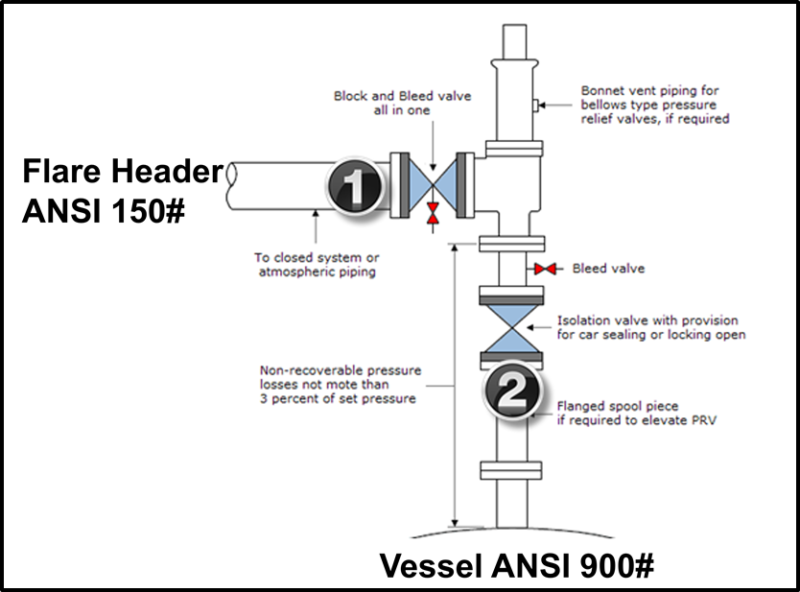
In order to ensure that the maximum allowable accumulation pressure of any system or apparatus protected by a safety valve is never exceeded, careful consideration of the safety valve’s position in the system has to be made. As there is such a wide range of applications, there is no absolute rule as to where the valve should be positioned and therefore, every application needs to be treated separately.
A common steam application for a safety valve is to protect process equipment supplied from a pressure reducing station. Two possible arrangements are shown in Figure 9.3.3.
The safety valve can be fitted within the pressure reducing station itself, that is, before the downstream stop valve, as in Figure 9.3.3 (a), or further downstream, nearer the apparatus as in Figure 9.3.3 (b). Fitting the safety valve before the downstream stop valve has the following advantages:
• The safety valve can be tested in-line by shutting down the downstream stop valve without the chance of downstream apparatus being over pressurised, should the safety valve fail under test.
• When setting the PRV under no-load conditions, the operation of the safety valve can be observed, as this condition is most likely to cause ‘simmer’. If this should occur, the PRV pressure can be adjusted to below the safety valve reseat pressure.
Indeed, a separate safety valve may have to be fitted on the inlet to each downstream piece of apparatus, when the PRV supplies several such pieces of apparatus.
• If supplying one piece of apparatus, which has a MAWP pressure less than the PRV supply pressure, the apparatus must be fitted with a safety valve, preferably close-coupled to its steam inlet connection.
• If a PRV is supplying more than one apparatus and the MAWP of any item is less than the PRV supply pressure, either the PRV station must be fitted with a safety valve set at the lowest possible MAWP of the connected apparatus, or each item of affected apparatus must be fitted with a safety valve.
• The safety valve must be located so that the pressure cannot accumulate in the apparatus viaanother route, for example, from a separate steam line or a bypass line.
It could be argued that every installation deserves special consideration when it comes to safety, but the following applications and situations are a little unusual and worth considering:
• Fire - Any pressure vessel should be protected from overpressure in the event of fire. Although a safety valve mounted for operational protection may also offer protection under fire conditions,such cases require special consideration, which is beyond the scope of this text.
• Exothermic applications - These must be fitted with a safety valve close-coupled to the apparatus steam inlet or the body direct. No alternative applies.
• Safety valves used as warning devices - Sometimes, safety valves are fitted to systems as warning devices. They are not required to relieve fault loads but to warn of pressures increasing above normal working pressures for operational reasons only. In these instances, safety valves are set at the warning pressure and only need to be of minimum size. If there is any danger of systems fitted with such a safety valve exceeding their maximum allowable working pressure, they must be protected by additional safety valves in the usual way.
In order to illustrate the importance of the positioning of a safety valve, consider an automatic pump trap (see Block 14) used to remove condensate from a heating vessel. The automatic pump trap (APT), incorporates a mechanical type pump, which uses the motive force of steam to pump the condensate through the return system. The position of the safety valve will depend on the MAWP of the APT and its required motive inlet pressure.
This arrangement is suitable if the pump-trap motive pressure is less than 1.6 bar g (safety valve set pressure of 2 bar g less 0.3 bar blowdown and a 0.1 bar shut-off margin). Since the MAWP of both the APT and the vessel are greater than the safety valve set pressure, a single safety valve would provide suitable protection for the system.
Here, two separate PRV stations are used each with its own safety valve. If the APT internals failed and steam at 4 bar g passed through the APT and into the vessel, safety valve ‘A’ would relieve this pressure and protect the vessel. Safety valve ‘B’ would not lift as the pressure in the APT is still acceptable and below its set pressure.
It should be noted that safety valve ‘A’ is positioned on the downstream side of the temperature control valve; this is done for both safety and operational reasons:
Operation - There is less chance of safety valve ‘A’ simmering during operation in this position,as the pressure is typically lower after the control valve than before it.
Also, note that if the MAWP of the pump-trap were greater than the pressure upstream of PRV ‘A’, it would be permissible to omit safety valve ‘B’ from the system, but safety valve ‘A’ must be sized to take into account the total fault flow through PRV ‘B’ as well as through PRV ‘A’.
A pharmaceutical factory has twelve jacketed pans on the same production floor, all rated with the same MAWP. Where would the safety valve be positioned?
One solution would be to install a safety valve on the inlet to each pan (Figure 9.3.6). In this instance, each safety valve would have to be sized to pass the entire load, in case the PRV failed open whilst the other eleven pans were shut down.
If additional apparatus with a lower MAWP than the pans (for example, a shell and tube heat exchanger) were to be included in the system, it would be necessary to fit an additional safety valve. This safety valve would be set to an appropriate lower set pressure and sized to pass the fault flow through the temperature control valve (see Figure 9.3.8).
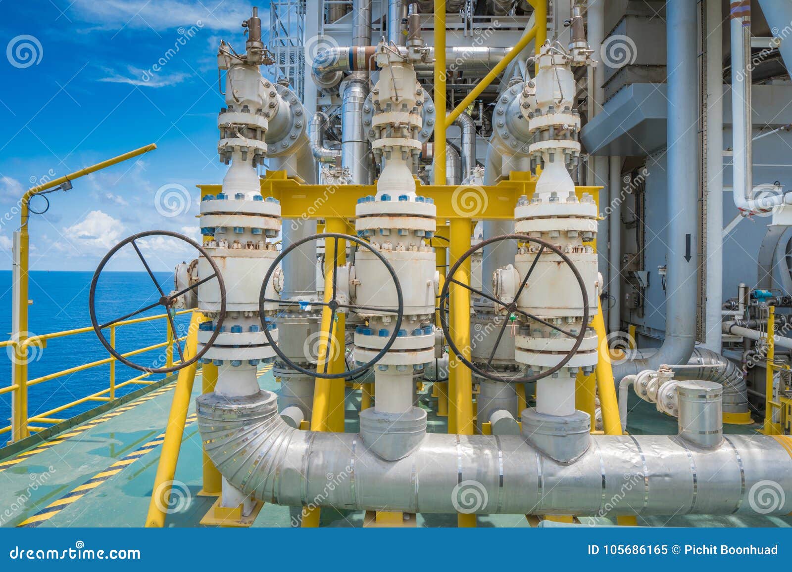
In petroleum and natural gas extraction, a Christmas tree, or "tree", is an assembly of valves, casing spools, and fittings used to regulate the flow of pipes in an oil well, gas well, water injection well, water disposal well, gas injection well, condensate well, and other types of well.
The first primitive Christmas Tree was used by the Hamill Brothers to bring Spindletop under control. It consisted of a T-valve, with a 6-inch (150 mm) and 8-inch (200 mm) valve on the vertical pipe, and a 6-inch valve on the horizontal pipe. The vertical valve was closed first, and then the valve to the horizontal pipe.
Christmas trees are used on both surface and subsea wells. It is common to identify the type of tree as either "subsea tree" or "surface tree". Each of these classifications has a number of variations. Examples of subsea include conventional, dual bore, mono bore, TFL (through flow line), horizontal, mudline, mudline horizontal, side valve, and TBT (through-bore tree) trees. The deepest installed subsea tree is in the Gulf of Mexico at approximately 9,000 feet (2,700 m). Current technical limits are up to around 3000 metres and working temperatures of −50 to 350 °F (−46 to 177 °C) with a pressure of up to 15,000 psi (100 MPa).
The primary function of a tree is to control the flow, usually oil or gas, out of the well. (A tree may also be used to control the injection of gas or water into a non-producing well in order to enhance production rates of oil from other wells.) When the well and facilities are ready to produce and receive oil or gas, tree valves are opened and the formation fluids are allowed to go through a flow line. This leads to a processing facility, storage depot and/or other pipeline eventually leading to a refinery or distribution center (for gas). Flow lines on subsea wells usually lead to a fixed or floating production platform or to a storage ship or barge, known as a floating storage offloading vessel (FSO), or floating processing unit (FPU), or floating production, storage and offloading vessel (FPSO).
A tree often provides numerous additional functions including chemical injection points, well intervention means, pressure relief means, monitoring points (such as pressure, temperature, corrosion, erosion, sand detection, flow rate, flow composition, valve and choke valve position feedback), and connection points for devices such as down hole pressure and temperature transducers (DHPT). On producing wells, chemicals or alcohols or oil distillates may be injected to preclude production problems (such as blockages).
Functionality may be extended further by using the control system on a subsea tree to monitor, measure, and react to sensor outputs on the tree or even down the well bore. The control system attached to the tree controls the downhole safety valve (SCSSV, DHSV, SSSV) while the tree acts as an attachment and conduit means of the control system to the downhole safety valve.
Tree complexity has increased over the last few decades. They are frequently manufactured from blocks of steel containing multiple valves rather than being assembled from individual flanged components. This is especially true in subsea applications where the resemblance to Christmas trees no longer exists given the frame and support systems into which the main valve block is integrated.
Note that a tree and wellhead are separate pieces of equipment not to be mistaken as the same piece. The Christmas tree is installed on top of the wellhead. A wellhead is used without a Christmas tree during drilling operations, and also for riser tie-back situations that later would have a tree installed at riser top. Wells being produced with rod pumps (pump jacks, nodding donkeys, grasshopper pumps, and so on) frequently do not utilize any tree owing the absence of a pressure-containment requirement.
Subsea and surface trees have a large variety of valve configurations and combinations of manual and/or actuated (hydraulic or pneumatic) valves. Examples are identified in API Specifications 6A nd 17D.
A basic surface tree consists of two or three manual valves (usually gate valves because of their flow characteristics, i.e. low restriction to the flow of fluid when fully open).
A typical sophisticated surface tree will have at least four or five valves, normally arranged in a crucifix type pattern (hence the endurance of the term "Christmas tree"). The two lower valves are called the master valves (upper and lower respectively). Master valves are normally in the fully open position and are never opened or closed when the well is flowing (except in an emergency) to prevent erosion of the valve sealing surfaces. The lower master valve will normally be manually operated, while the upper master valve is often hydraulically actuated, allowing it to be used as a means of remotely shutting in the well in the event of emergency. An actuated wing valve is normally used to shut in the well when flowing, thus preserving the master valves for positive shut off for maintenance purposes. Hydraulic operated wing valves are usually built to be fail safe closed, meaning they require active hydraulic pressure to stay open. This feature means that if control fluid fails the well will automatically shut itself in without operator action.
The right hand valve is often called the flow wing valve or the production wing valve, because it is in the flowpath the hydrocarbons take to production facilities (or the path water or gas will take from production to the well in the case of injection wells).
The left hand valve is often called the kill wing valve (KWV). It is primarily used for injection of fluids such as corrosion inhibitors or methanol to prevent hydrate formation. In the North Sea, it is called the non-active side arm (NASA). It is typically manually operated.
The valve at the top is called the swab valve and lies in the path used for well interventions like wireline and coiled tubing. For such operations, a lubricator is rigged up onto the top of the tree and the wire or coil is lowered through the lubricator, past the swab valve and into the well. This valve is typically manually operated.
Some trees have a second swab valve, the two arranged one on top of the other. The intention is to allow rigging down equipment from the top of the tree with the well flowing while preserving the two-barrier rule. With only a single swab valve, the upper master valve is usually closed to act as the second barrier, forcing the well to be shut in for a day during rig down operations. However, avoiding delaying production for a day is usually too small a gain to be worth the extra expense of having a Christmas tree with a second swab valve.
Subsea trees are available in either vertical or horizontal configurations with further speciality available such as dual bore, monobore, concentric, drill-through, mudline, guidelineless or guideline. Subsea trees may range in size and weight from a few tons to approximately 70 tons for high pressure, deepwater (deeper than 3,000 ft or 910 m) guidelineless applications. Subsea trees contain many additional valves and accessories compared to surface trees. Typically, a subsea tree would have a choke valve (permits control of flow), a flowline connection interface (hub, flange or other connection), subsea control interface (direct hydraulic, electro hydraulic, or electric), and sensors for gathering data such as pressure, temperature, sand flow, erosion, multiphase flow, and single phase flow such as water or gas.
Linsley, Judith; Rienstrad, Ellen; Stiles, Jo (2002). Giant Under the Hill, A History of the Spindletop Oil Discovery at Beaumont, Texas in 1901. Austin: Texas State Historical Association. pp. 121–126. ISBN 9780876112366.


 8613371530291