
ndt wire rope inspection quotation

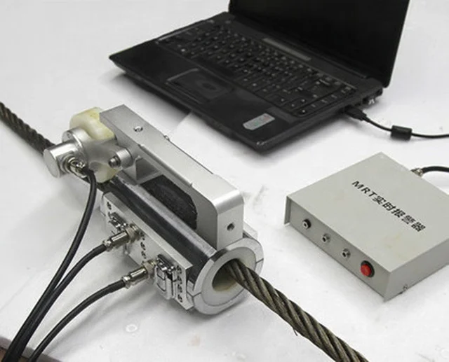
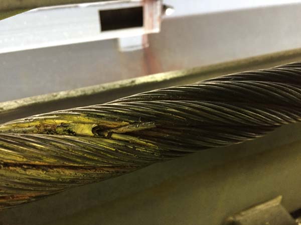
TKS provides wire rope testing using the following methods; magnetic flux leakage (MFL) testing, ultrasonic testing, acoustic emission testing, and visual inspection services on wire rope and steel bridge cables. Wire rope is fatigued through complex stress states over its lifetime and must guarantee the safety of human life and expensive equipment. Broken strands on the rope exterior can be found by visual inspections, but the condition of the core and inner wire strands cannot be seen. Many wire rope structures start to wear from the inside out.
Our NDT technology provides real engineering data that can be used to assess the structural integrity, allowable load rating, and remaining life of wire rope.

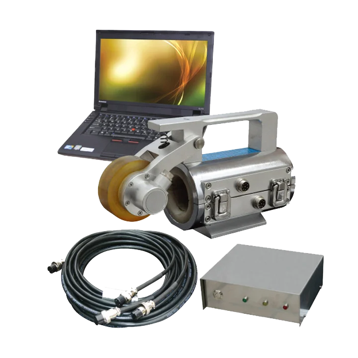
The Magnograph® series of wire rope NDT testers are the leading non-destructive instrument to test the condition of steel rope sections. Detecting corrosion and broken wires, this is simply not possible with visual inspections.
This state-of-the-art NDT testing of wire rope quickly and efficiently identifies defects through the entire cross section of rope. Even non-skilled personnel can operate the Magnograph. View real-time data and perform post-test data analysis easier than ever before.
Magnograph® MAG II is designed to test ropes from 12-64mm (1/2 to 2-1/2 inch) diameters. It utilizes 5 different sizes of interchangeable rope guides in the sensor head.
Depend on the Magnograph® for professional wire rope inspection you can trust. By using Magnograph® and its computerized systems, you will benefit from many outstanding advantages:
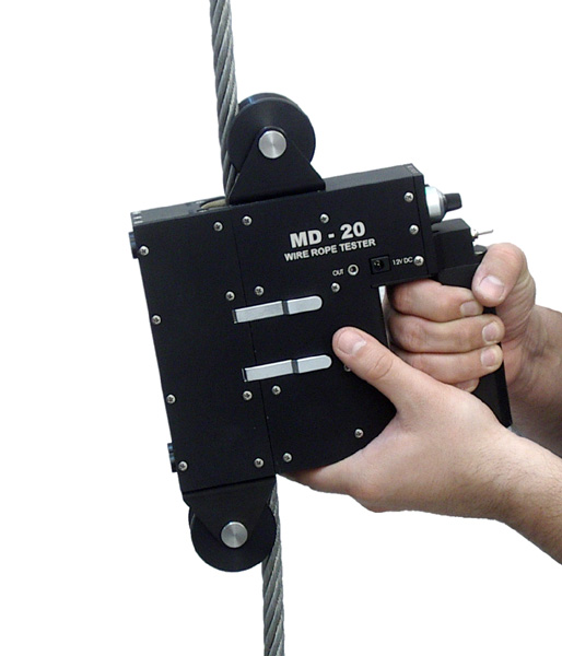
Non-destructive wire rope inspection involves determining the condition of wire rope still in service to ensure that it is safe for use. Every steel wire rope, which is subject to corrosion, abrasion, and fatigue, will fail one day if it is not discarded in time. Steel wire rope flaw detectors enable accurate measurement of loss of metallic area (LMA) and detection of outer and inner localized flaws (LF), such as broken wires, strands, pitting corrosion. Our wire rope test and inspection equipment is suitable for underground and surface mining, cranes and heavy lifting onshore and offshore, cable ways, cable bridges, elevators, guy ropes of flare stacks and masts, overhead transmission lines, etc.
This is because the end ofuser rope must be stronger than lead insurers, so they can lessstand the test of time and even if the end of a rope. It are also used in manufacturing areas, construction, and many other areas of construction.
Stainless steel wire rope is one of the most convenient materials and can be bought in bulk for the long time. even if steel wire is high, it is important to know the shape and size of the wire rope.
One of the most important things to wire in places is your customers ’ work. Before buying wire rope at Alibaba.com, it is important to know what type of customers is wire rope inspectors and whether they ’ re going to work or any other place where your customers work, wire rope inspectors should be able to provide wire rope inspections to any customers, so they can check whether the quality is a quality or a indicator. wire rope inspectors should be able to check the quality of materials used when wire rope is used, and even if it is at the same time as your customers, wire should check at any end of the day.
One of the main purposes of wire rope inspections is to identify the condition that the wire rope is ised and, according to the quality of the attached, and the wire itself. One of the most important types of wire rope inspections is to make the that, or the other, a welded steel design needs to be checked before, and any wire rope is applied. Hence, wire rope inspectors should be able to check the quality of the wire rope used by installing wire ropepes.

we provide quality products and customer service that our customers are accustomed to. Herb has invested time, over the past five years, with a transition team lead by Ori and Joe Shtekler to ensure a smooth transition. To NDT Technology LLC.
NDT Technology, LLC. is a developer and manufacturer of nondestructive test instrumentation for the in-service inspection of wire ropes and cables. Our company is the world’s premier maker of wire rope inspection instrumentation. Our success in this niche business can be attributed to the superior performance of our products and our never-ending pursuit of innovation.
Our wire rope NDE equipment is especially suited for the inspection of so-called high-value wire ropes (i.e., large diameter (>100mm) subsea construction ropes with lengths in excess of 2000m). Our rope testers also show great promise for the inspection of spiral strand.
Magnetic flux leakage (MFL) detection is one of the most widely used and best performing wire rope nondestructive testing (NDT) methods for more than a decade. However, the traditional MFL detection has the disadvantages of single source of information, low precision, easy to miss detection, and false detection. To solve these problems, we propose a method of fusion recognition of magnetic image features and infrared image features. A denoising algorithm based on Hilbert vibration decomposition (HVD) and wavelet transform is proposed to denoise the MFL signal, and the modulus maxima method is used to locate and segment the defect. An infrared image acquisition system was designed to collect the infrared image of the surface of the wire rope. Digital image processing techniques are used to segment infrared defect images. The features of the MFL image and the infrared image are extracted separately for fusion. The fusion feature is input into the nearest neighbor (NN) algorithm for quantitative identification, and the same data are input into the backpropagation (BP) neural network for comparison verification. The experimental results show that the fusion of MFL features and infrared features effectively improves the recognition rate of wire rope defects and reduces the recognition error.
Wire ropes play an indispensable role in industrial production, commercial services, and high-tech industries in the modern world. The safety of the wire rope during these production processes is very important because it is usually related to the safety of life and property. Nondestructive testing (NDT) of wire ropes can identify various safety hazards in advance [1]. There are many methods for NDT of steel wire ropes. In GB/T5616 NDT application guidelines, they are divided into 6 categories and more than 70 types [2]. At present, the most commonly used methods at home and abroad include ultrasonic testing [3], radiation testing [4], eddy current testing [5], electromagnetic testing, and infrared testing. Since most of the steel wire ropes are made of high-carbon steel with good magnetic permeability, the electromagnetic detection method is very suitable for NDT of wire ropes and has become the most widely used and most mature method [6]. In addition to conventional detection methods, as technology advances, new detection methods continue to emerge. Infrared thermography (IRT) technology has attracted more and more attention because of its fast, intuitive, noncontact, and pollution-free advantages [7]. How to supplement and develop different kinds of methods to play their respective advantages and avoid their respective shortcomings is the focus of current research.
The principle of magnetic flux leakage (MFL) testing is when the wire is magnetized in the axial direction, a magnetic field is generated inside the wire. If there is a defect on the surface of the wire rope, the magnetic field will leak through this defect to form a MFL. At this time, the magnetic sensitive element is used to collect the MFL information along the circumferential direction of the wire rope, and the broken wire position and quantity can be obtained after the analysis and processing [8].
The first step in the MFL testing of wire ropes is magnetization. Magnetization is divided into coil magnetization and permanent magnet magnetization according to the excitation source [9]. The advantage of coil magnetization is that the magnitude of the magnetic field can be freely changed by changing the current. Okolo and Meydan [10] magnetizes the pipe to be tested by applying a pulse current on the excitation coil and then measures the leakage flux through a magnetic field sensor. However, the alternating magnetic field is prone to skin effect and eddy current, which is not conducive to subsequent MFL detection. Singh et al. [11] used two saddle coils to magnetize the wire rope and then uses a giant magnetoresistive (GMR) sensor that is inexpensive and easy to use to detect the defect leakage magnetic field. Park et al. [12] proposed a long-span bridge steel cable automatic monitoring system that uses strong permanent magnets to establish magnetic flux in the steel cable to be inspected and uses a Hall sensor to detect the MFL generated by the defect.
Sensitive magnetic sensors are critical for MFL testing technology. Zhao [13] designed a MFL testing device based on a Hall array sensor. In view of the problem that the traditional induction coil collects data unevenly due to large span, four different structured printed circuit board (PCB) coils are designed to detect the leakage flux of different components. A spatial notch filter is proposed to filter out the strand noise of the MFL image. However, Hall sensors have lower sensitivity and stability than GMR sensors. Pham et al. [14] designed a MFL testing device based on a planar Hall magnetoresistive sensor, which is used to detect shallow defects on the lower surface of oil and gas pipelines due to its high sensitivity and low thermal drift. Xiucheng et al. [15] designed a circular sensor array based on a tunnel magnetoresistive (TMR) sensor to detect slight defects on the surface of the wire rope and judge the defect position based on the MFL information. But it only verifies the effect of the TMR sensor, and there is no signal for accurate identification.
The processing of the detected MFL signal is crucial, which is related to the ability to accurately identify the location and number of defects. Zhang et al. [16] used a detection device consisting of 18 GMR sensor arrays and an ARM controller board to obtain the residual magnetic distribution of the wire rope. The system control board is composed of an encoding module, a signal amplifier module, an array control module, a data storage module, and a CPU module. The CPU core uses STM32F407. All system operations are controlled by the ARM9 core. The Hilbert–Huang transform is used to decompose the MFL signal, and then, each layer of the signal is subjected to wavelet decomposition based on compressed sensing. However, the compression sensing structure is complex, the amount of calculation is large, and the filtering of noise is not ideal. Zheng and Zhang [17] used an image processing method that converts the noise-reduced wire rope MFL signal into a grayscale image and then converts the grayscale image into a pseudo color image. The features such as the color moment of the defect image are extracted for recognition, and the recognition accuracy is better than the gray image. Liu et al. [18] proposed a method based on notch filtering combined with wavelet denoising to filter out the noise of the wire rope signal. Compared with traditional low-pass filtering and adaptive analysis, this method is more accurate and reliable.
IRT is a promising technology for quantitative NDT of objects based on heat. Compared with other NDT methods, IRT has the advantages of noncontact data acquisition and sensitivity to near-surface defects of components [19]. Because the temperature difference between the defect and the intact surface is obvious, IRT is highly sensitive to small defects of the metal material. Eddazi and Belattar [20] used IRT and finite element analysis to perform NDT on the aluminum body of the conveyor, and the degree of corrosion of the fuselage was determined by analyzing the temperature difference between the heat flux value and the corrosion thickness.
In order to solve the shortcomings of traditional MFL detection information, such as single source, low precision, and easy to be interfered, we propose a fusion recognition method of magnetic image features and infrared image features. In order to solve the problem of MFL signal noise, a denoising algorithm based on Hilbert vibration decomposition (HVD) and wavelet transform is proposed to denoise the MFL signal. The modulus maxima method is used to locate the defect and segment the image. In order to collect the infrared image of the wire rope surface, we designed an infrared image acquisition system. The infrared defect image is segmented using digital image processing techniques. The features of the MFL image and the infrared image are separately extracted for fusion. This paper adopts the feature-level fusion method. In order to verify whether the MFL feature is effective after fusion with the infrared feature, we input the fusion feature and the MFL defect feature into the nearest neighbor (NN) algorithm for quantitative identification. At the same time, in order to eliminate the influence of the algorithm on the results, we input the same data into the back propagation (BP) neural network for comparison verification. The experimental results show that the fusion of infrared image information and MFL signal effectively improves the recognition rate of wire rope defects and reduces the recognition error.
The wire rope MFL signal acquisition device under the unsaturated magnetic excitation of the literature [23] is cited herein. As shown in Figure 1, the sensor array is used to collect the MFL information of the wire rope defect. The unsaturated magnetic excitation module is used to generate a uniform excitation field to magnetize the wire rope. The sensor array module is integrally provided with the unsaturated magnetic excitation module. The unsaturated magnetic excitation module is composed of a plurality of rod-shaped permanent magnets, and the permanent magnets are evenly arranged along the circumferential direction of the wire rope. All permanent magnets have the same magnetic pole direction. The sensor array consists of 18 highly sensitive GMR sensors. The sensor model is AAH002 analog GMR sensor. The linear output range for weak magnetic fields of the sensor is 0.6–3.0 Oe, the magnetic sensitivity range is 11–18 mV/V-Oe, and the voltage output range is 26.1–217.5 mV. The GMR sensors are evenly distributed along the circumference of the wire rope, with a linear distance of 9.94 mm between the center points of each sensor. Each GMR sensor has a distance of 11 mm from the surface of the wire rope. Since the sensitive surface of the GMR sensor is perpendicular to the surface of the wire rope, the acquired MFL component is a radial component. The collecting device moves at a constant speed along the axial direction of the wire rope, and the controller sequentially collects the MFL data of 18 channels. The encoder collects 1024 points per 0.31 m. The wire rope has a diameter of 28 mm, a structure of 6 × 36, and a length of 6 m.
Figure 2 shows the raw unfolded data for the wire rope MFL signal. The highest peak portion in the figure is not the defect signal but the magnetic pole portion generated during the excitation process.
The wire rope infrared image acquisition system consists of two parts: wire rope heating device and infrared camera. Since the picture taken at normal temperature is not ideal, the wire must be heated before the infrared image of the wire rope is taken. The wire rope heating device is a cylindrical stainless steel sleeve which is covered with a heating belt. When it is necessary to heat the wire rope, the sleeve is placed on the wire rope for heating. If the temperature of the wire rope heating temperature is too high or too low, the color of the infrared image defect will be similar or even the same as the surrounding environment, which may result in the inability to accurately extract the defect. After repeated experiments, the heating temperature of the wire rope was set at 36–40°C, and the infrared image captured in this temperature range was of good quality.
As shown in Figure 3, the heating device heats the local position of the wire rope to a specified temperature and then photographs using an infrared camera. As shown in Figure 4, the infrared camera model is FLUKE TiX660.
The MFL signal collected by the MFL detecting device contains a large amount of noise before being processed. It includes the noise caused by the uneven excitation, the influence of the earth’s magnetic field, the wave noise caused by the spiral structure of the wire rope, the influence of the lift distance, and the jitter of the wire rope. The quality of noise processing will greatly affect the quantitative identification in the later stage. If noise is not filtered out, the defect signal will be submerged in the noise. Eventually, the defect will not be recognized. In order to remove the influence of noise in the original signal, the Hilbert vibration decomposition (HVD) and wavelet transform are used to denoise the signal.
In order to proceed to the next step, it is necessary to extract the defective area of the infrared image. Since the broken wire of the wire rope is a heat insulating-type defect, the temperature of the defect is significantly higher than the normal connection of the steel wire. IRT is greatly affected by external factors, such as oil stains, dross, and uneven heating. Because there is a large amount of oil between the wire rope strands, and the oil substances heat up faster than the metal substances under the external temperature, the oil temperature between the strands is also higher than the normal position of the steel ropes.
The features of the MFL defect image and the infrared defect image obtained in the foregoing are, respectively, extracted and fused. Figure 12 shows several broken wires photographs, MFL defect grayscale images, and infrared defect images. In this paper, the morphological features of the defect image are extracted including area, squareness, and elongation; and the seventh-order invariant moments have a total of 10 features as quantitatively identified feature vectors.
Photos (above), MFL grayscale images (middle), and infrared binary images (below) of 6 different defects: (a) one broken wire; (b) two broken wires; (c) three broken wires; (d) four broken wires; (e) five broken wires; (f) seven broken wires.
In the experiments quantitatively identified in this paper, the wire rope is 28 mm in diameter and 6 36 in structure. The wire rope has six types of broken wires: one wire, two wires, three wires, four wires, five wires, and seven wires. The dimension of the defect is 15 mm. A total of 187 defective samples were obtained in this experiment. A total of 147 samples were randomly selected from 187 samples as training samples, and the remaining 40 samples were used as test samples.
The MFL defect feature and the infrared defect feature are fusion and input into the NN algorithm. Figure 13 shows the recognition rate of the fusion feature. When the recognition error is allowed to be 0.93%, the recognition success rate is 97.87%, and the maximum recognition error is not more than 1.39%. The percentage of broken wire refers to the percentage of wire rope broken wire to the total number of wire ropes. When the percentage error is less than the maximum allowable identification error, it can be considered as the correct result.
In order to solve the problem that the wire rope defect information source is single and the recognition accuracy is not high, this paper proposes a method of fusion recognition of magnetic image features and infrared image features. We have collected the wire rope MFL signal under nonsaturated magnetic excitation. In order to filter out a large amount of noise in the MFL signal, we have proposed a denoising algorithm based on HVD and wavelet transform to filter the MFL signal. The gray scale of the MFL data after noise reduction is normalized, and the defect portion is positioned and segmented by the modulus maximum value method. We have designed a wire rope infrared image acquisition system that was used to acquire infrared images of wire rope surface defects. We take the RGB image segmentation of the acquired infrared image to obtain the ROI and use the area method to obtain the binary image of the defective portion. The morphological features and the seventh-order invariant moment features of the MFL image and the infrared defect image are extracted separately. To verify the validity of the fusion of features, we have designed two sets of quantitative recognition experiments. The MFL defect feature and the fusion feature are, respectively, used as input to the NN algorithm. At the same time, in order to avoid the influence of the recognition algorithm, we input the same data into the BP neural network for comparison. The experimental results show that the recognition rate of the fusion feature is significantly higher than that of the MFL defect feature, whether it is the NN algorithm or the BP neural network.
Our experiments verify that the fusion of infrared image information and MFL signals is effective in improving the recognition rate of wire rope defects. Future research work will focus on the improvement of the wire rope infrared image acquisition system and the optimization of the image fusion method.

Magnetic flux leakage (MFL) detection is commonly employed to detect wire rope defects. However, nondestructive testing (NDT) of a wire rope still has problems. A wire rope nondestructive testing device based on a double detection board is designed to solve the problems of large volume, complex operations, and limited circumferential resolution due to sensor size in traditional devices. The device adopts two magnetic sensor arrays to form the double detection board and collects the MFL data of the magnetized wire rope. These sensors on the double detection board are staggered and evenly arranged on the circumference of the wire rope. A super-resolution algorithm based on interpolation uses non-subsampled shearlet transform (NSST) combining principal component analysis (PCA) and Gaussian fuzzy logic (GFL) and fuses the data of double detection board to improve the resolution and quality of defect images. Image quality measurement and comparison experiments are designed to verify that defect images are effectively enhanced. An AdaBoost classifier is designed to classify defects by texture features and invariant moments of defect images. The experimental results show that the detection device not only improves the circumferential resolution, but also the operation is simple; the resolution and quality of the defect images are improved by the proposed super-resolution algorithm, and defects are identified by using the AdaBoost classifier.
Wire ropes are widely used in industrial applications such as coal, mining, and other industrial applications because of their advantages: good flexibility, high strength, and strong bearing capacity. The safe operation of wire rope affects the safety of industrial production and personnel. Detecting the damage of wire ropes has important social and economic benefits. The nondestructive testing of a wire rope includes electromagnetic detection, ultrasonic detection, optical detection, X-ray detection, and acoustic emission detection methods. The electromagnetic detection method has widely been used and promoted in current research and application. It includes magnetic flux leakage (MFL) detection, eddy current detection, magnetic memory detection, and magnetic particle detection. MFL detection is the most commonly used method due to its simple structure and strong applicability. The principle of MFL detection is based on the distribution of leakage magnetic field generated by the magnetized wire rope. The damage of the wire rope will affect the magnetic flux leakage distribution on the surface, and the damage detection can be realized by measuring the leakage magnetic field [1].
In the MFL detection method, the magnetization method of the wire rope includes coil magnetization [2, 3] and permanent magnet magnetization [4, 5]. Sun et al. [2] proposed an opening electric magnetizer based on the magnetic control for a C-like electric loop-coil. Its magnetization effect was confirmed by simulations and experiments with the designed 3-D models and prototypes. Wu et al. [3] combined Helmholtz-like coils and a custom-made magnetic shield to design the electromagnet magnetizer. Its structural parameters were optimized by the orthogonal test method. Coil magnetization method requires current flow into multiple coils to realize magnetization, which will lead to problems of coil heating and complicated operation. Permanent magnet magnetization is easy to operate. And permanent magnets are usually uniformly arranged around the circumference of the wire rope for magnetization. Sun et al. [4] proposed an open permanent magnet magnetization method, which solved the problem of strong magnetic force and large weight in the yoke magnetic method. Yu et al. [5] considered the effects of excitation system on the performance of leakage magnetic nondestructive testing and optimized the dimensions of the yoke. Wang et al. [6] combined the structural models for dynamic magnetic field balancing and magnetic focusing, which effectively reduced the interference produced by the interactions between the environmental magnetic fields and the wire rope strand. Pan et al. [7] proposed a simple and portable magnetic detector device, which was very light and easy to design and manufacture.
The leakage magnetic field on the surface of the wire rope is usually collected by magnetic sensors, which includes Hall sensor [8], coil sensor [9], fluxgate sensor [10], giant magnetoresistance (GMR) sensor [11], tunnel magnetoresistance (TMR) sensor [12]. The circumferential resolution and sensitivity of magnetic sensors array are important for the detection of wire rope damage. The circumferential resolution of magnetic sensor array affects the location of wire rope damage. Kim and Park [8] designed a hall sensor array to detect wire rope damage; the MFL signal at the defect was enveloped and compared with the threshold to quantify the defect. However, the low circumferential resolution due to Hall sensor size made it difficult to accurately locate the circumferential position of the damage. And the sensitivity of the magnetic sensor also affects the effectiveness of detecting damages. Yan et al. [9] designed a kind of iron core as coil winding skeleton, and their design improved the signal-to-noise ratio (SNR) of magnetic flux leakage signal and simplified coil sensor. Lei et al. [11] proposed a detection device based on high-sensitivity GMR sensors, which solved the problem of low SNR caused by the small diameter and large lift off. Liu et al. [12] designed a circular TMR-based MFL sensor for slight wire rope flaw detection and detected accurately the axial and circumferential positions of these broken wire flaws.
After the magnetic sensors obtain the leakage magnetic field on the surface of the wire rope, signal processing and image processing techniques are used to achieve qualitative and quantitative detection of defects. The MFL signal of the wire rope contains various background noises. The signal processing methods are used to filter out these noises, which can achieve the qualitative analysis of defects. Zhang et al. [13] designed a wavelet filtering algorithm combining the Hilbert–Huang transformation with compression sensing, which effectively suppress the system noise. Wang [14] used the wavelet method to analyze the magnetic flux leakage signal at the defect and verified the wavelet base db4 with the best noise reduction effect. Liu et al. [15] proposed a wire rope detection signal processing method combining notch filter and wavelet denoising, which could effectively distinguish wire rope defect signal and strand signal, with high detection accuracy, even for the inner defect. Image processing technology can visualize the magnetic flux leakage signal of defects and improve the quality and resolution of defect images, which is important for the quantitative analysis of defects. Zhao et al. [16] used circumferential interpolation to improve the circumferential resolution of the original MFL images and achieved good detection results. Zhang et al. [17] proposed wavelet super-resolution technology to improve the resolution of the defect image, making the edge information of the defect more obvious and easier to identify. Tan and Zhang [18] proposed a super-resolution reconstruction method based on Tikhonov regularization to enhance defect image and verified that image property was the best when super-resolution result was triple. However, this method did not apply the exact image quality measurement experiments to verify the effect of defect image enhancement. In addition to these image processing techniques to improve resolution, some image fusion methods can also be used to enhance the MFL image of wire rope defects. In the field of image fusion, traditional multiscale image representation methods have pyramid, wavelet, curvelet, and shearlet. Among them, discrete wavelet transform is a common method, but it has some disadvantages such as not shift invariance, poor directionality, and not a time-invariant transform [19]. Compared to the wavelet transform, contourlet transform has good multiresolution and directionality, but it lacks shift invariance. Non-subsampled contourlet transform is proposed to solve this problem, which adds shift invariance to the contourlet transform, and it can better express the edge and texture information of the image [20]. However, it is not efficient and takes a long time. To solve this problem, NSST is proposed. It not only has short running time and can meet the requirements of real-time [21], but also can extract more detailed features of the target image in different directions.
In order to solve the problems of large volume, complex operations, and limited circumferential resolution due to sensor size in traditional devices, a MFL detection device based on the double detection board is designed. The double detection board consists of magnetic sensors, and these sensors are staggered and evenly arranged on the circumference of the wire rope. The wire rope is magnetized by permanent magnets, and the double detection board collects the surface MFL data of the wire rope. A super-resolution algorithm based on interpolation is applied to double the resolution of defect images. NSST is applied to super-resolution images, which are decomposed into high-frequency coefficients and low-frequency coefficients. For high-frequency coefficients, PCA is implemented as a fusion rule. For low-frequency coefficients, GFL is implemented as a fusion rule. After fusing these coefficients, inverse NSST is applied to reconstruct the fused image. The proposed algorithm fuses the data of double detection board to improve the quality of defect images. Various image quality measurement and comparison experiments are performed, and the results show that spatial resolution of defect images is enhanced effectively and high-quality images are obtained. Image descriptions of texture features and invariant moments are extracted as the feature vector of the defect, which are the input of the AdaBoost classifier and are used to identify the defects.
The principle of the whole experiment is based on the unsaturated magnetic excitation detection method. Under the excitation state, magnetic field lines generated by the permanent magnet pass through the air inside the excitation rope to form magnetic loops, and there are weak MFL signals at defect as shown in Figure 1(a). Defect information is analyzed by these weak MFL signals. Because the unsaturated magnetic excitation detection method can obtain smoother defect flux leakage signals than the remanence detection method [18], it is applied in this paper. More details about unsaturated magnetic excitation methods can also be found in [18].
The principle of the double detection board is to obtain more circumferential magnetic flux leakage information through the two detection boards. A single detection board limits the number of sensors that can be accommodated due to the sensor size, which also limits the collection of circumferential MFL information of the wire rope. Two detection boards are interlaced around the wire rope, which can collect more circumferential MFL information than one detection board. Double detection board combines with unsaturated excitation detection method constituting the whole experimental platform.
The unsaturated magnetic excitation module contains 12 permanent magnets. Permanent magnet material is NdFeB, remanence strength is 1.18 Tesla, and magnetization distance is 1.5 cm. Multiple elongated permanent magnets are evenly distributed around the circumference of the wire rope, and the wire rope is in the excited state. The double detection board consists of two sensor arrays as show in Figure 2. And each sensor array is made of 18 giant magnetoresistance (GMR) sensors. The number of sensors is determined by the lift off distance and sensor size [18]. In order to ensure that two sensor arrays do not repeatedly collect the MFL data on the surface of the wire rope, the circumferential angle of the sensor is θ (θ = 10°), and the axial distance between the two sensor arrays is L (L is set to 1 cm) as shown in Figure 2. As shown in Figure 3, these sensors on the double detection board are staggered and evenly arranged on the circumference of the wire rope. The encoder generates control pulses to guarantee the equal spatial sampling. In addition, an ARM chip is used as the control chip, and secure digital (SD) memory card is used for the data storage.
The acquisition processes of the double detection board are as follows: the wire rope is magnetized by the excitation module, the double detection board and the encoder are connected with the control system, and entire acquisition system is loaded onto the magnetized wire rope. When the encoder moves along the wire rope axis, it sends out pulse signal. According to the encoder pulse signal, the double detection board is controlled to collect MFL data on the wire rope surface. There is an interval between the double detection board, which will cause the collected data to be of the same length, but the collected data on the surface of the wire rope are not completely coincident. Therefore, the MFL data of the double detection board cannot be simply superimposed together for subsequent processing. In order to improve the resolution of defect images by fusing the data of double detection board, data of the double detection board are divided into the first board data and the second board data. The double detection board is grouped for data processing and image processing to realize the quantitative identification of wire rope defects, and the processing steps are shown in Figure 4.
In the experiment, the diameter of steel wire rope is 28 mm and the structure is 6 × 37, and a total of 222 steel wires were used. Broken wires are the main form of wire rope breakage, and it is more difficult to identify the broken wires with small spacing, so it is more meaningful to identify the broken wires with small spacing. Artificial defect types included one discontinuity to five and seven broken wires as shown in Figure 5. And each defect is destroyed as small gap (about 0.2 cm).
Images of broken wires. (a) One broken wire. (b) Two broken wires. (c) Three broken wires. (d) Four broken wires. (e) Five broken wires. (f) Seven broken wires.
MFL data on the surface of wire rope collected by the experiment are shown as Figure 6. The original MFL data contain a lot of system noise. These noises include high-frequency magnetic flux leakage noise caused by uneven excitation between sensor channels, baseline drift caused by change of lift off, namely, low-frequency noise, and wave noise caused by spiral structure of the wire rope. These noises will affect the subsequent defect location and quantitative identification results as well as the repeatability of the results. In order to suppress these noises, an effective noise reduction algorithm is needed. Wavelet analysis has widely been used in digital signal processing. In this section, the data processing mainly includes the wavelet soft threshold denoising algorithm for the wire rope MFL signal processing.
Wavelet analysis [14, 15] has been well applied in wire rope MFL signal processing and proved to be an effective signal processing method. In this paper, wavelet analysis is used to decompose the MFL signal of the wire rope, and the high- and low-frequency coefficients of the signal are obtained, in which the high-frequency coefficient contains high-frequency magnetic flux leakage noise and wave noise and the low-frequency coefficient is the baseline. The high-frequency coefficient is treated by soft threshold, and the low-frequency coefficient is cleared. The proposed algorithm is as follows.(1)Select the n-th board MFL data (n = 1, 2).(2)Using db4 wavelet to decompose the data of a sensor channel with 7 level ( = 1–18), the data are shown in Figure 7, and wavelet decomposition is as follows:where is the low-pass filter, is the high-pass filter, and ; is the j-th low-frequency coefficient; is the j-th high-frequency coefficient; and is the reconstructed signal.(3)The low-frequency wavelet coefficient is cleared.(4)The high-frequency coefficients of each decomposition layer are processed by wavelet soft threshold, the universal threshold is “minimaxi.”(5)The processing wavelet coefficients are reconstructed by using the reconstruction equation (2), with which the denoising data are obtained as shown in Figure 8.
The two gray-scale images of the same defect. (a) One broken wire. (b) Two broken wires. (c) Three broken wires. (d) Four broken wires. (e) Five broken wires. (f) Seven broken wires.
Two source images were used to test these super-resolution algorithms, and their super-resolution renderings are shown in Figure 12. It is not easy to see the difference of image quality from these super-resolution results, which is due to the simple structure and texture of defect gray-scale images. Therefore, four measurement indexes were used to measure these super-resolution result images. The four measurement indicators are as shown in equations (11)–(17). Various super-resolution measurement results are shown in Table 6.(5)Mutual information (MI):where and , respectively, denote source images 1 and 2, is or , and is the normalized gray histograms of these source images and the fusion image, respectively.(6)Petrovics metric ():where shows the relation with source image 1 and fused image F looking to edge information. And shows the edge strength of source image 1.(7)Signal-to-noise ratio (SNR):(8)Structural similarity index measure (SSIM):The results from Table 6 show that all four quality measures of B3 exceed those of B1 and B2, which means that the proposed super-resolution algorithm has a good effect on gray-scale image enhancement of wire rope defects. Experimental results show that the proposed algorithm is feasible to wire rope defect image enhancement.
Quantitative identification is an important goal of wire rope nondestructive testing. In this part, texture features and seventh-order moment invariant features of defect images are extracted as feature vectors of defect images. These features include standard deviation, smoothness, third-order moment, consistency, and entropy, and the first, third, fifth and seventh moments of seven-order invariant moments. The designed AdaBoost classifier recognizes these defects by the feature vectors of defect images.
Broken wires are the main damage form of wire rope, and small spacing of broken wires is difficult to identify and more meaningful. In the quantitative identification experiment, 125 samples of concentrated broken wires were manufactured manually, with a small spacing of about 0.2 cm, and the types of broken wires included 1 to 5 and 7. The broken wire samples were randomly divided into training samples and test samples. The number of training samples was 94 (about 75%), and the number of test samples was 31 (about 25%). In this paper, the number of broken wires identified by AdaBoost classifier is converted into the percentage of broken wires, it represents the percentage of broken wires in the total wires and makes the classification of broken wires more intuitive. As shown in Figure 14, the identification result graph under different number of decision trees has the best recognition effect when the number of decision trees is 60. When the permissible error of broken wires is 0.45%, which means the permissible error is one wire, the recognition rate of broken wires reaches 93.55%, and the maximum error was not more than 0.9%.
In this paper, a wire rope nondestructive testing device based on the double detection board is designed to collect MFL data of the wire rope. The double detection board can collect more circumferential information of the wire rope surface. A super-resolution algorithm combining interpolation and NSST is used to improve the resolution and quality of defect images. The interpolation algorithm uses cubic interpolation to improve the resolution of defect images. NSST decomposes these high-resolution images to get high-frequency and low-frequency images, and GFL fuses low-frequency images and PCA fuses high-frequency images. The super-resolution algorithm fuses the data of the double detection board to produce better quality and higher resolution defect images. Various image quality measurements and comparison experiments are performed to show the effectiveness of the proposed algorithm. Compared with the super-resolution algorithm in literature [17, 26, 27], the proposed algorithm has better image quality improvement effect. After obtaining high-resolution defect images with good quality, the AdaBoost classifier was designed to identify these defect images so as to achieve quantitative recognition of broken wires. When the permissible error of broken wire is 0.45% (the permissible error is one wire), the highest recognition rate of the broken wire is 93.55%. In comparison with [18], the identification accuracy rate was 91.43% with the permissible error of one wire. Compared with [13], the accuracy was 93.75% under a permissible error of two wires. The proposed method outperforms existing methods. Quantitative identification results show that the AdaBoost classifier is feasible and effective for broken wires recognition.
In this paper, the three research works have been performed. Firstly, a wire rope nondestructive testing device based on the double detection board to address the disadvantages of the traditional detection device. Compared with traditional MFL traditional detection device, the proposed device has small volume, simple operations, and high circumferential resolution. Secondly, a super-resolution algorithm combining interpolation and NSST is used to fuse the MFL data of double detection board to improve the quality of defect images. Various image quality measurements and comparison experiments are performed to show the effectiveness of the proposed algorithm. Finally, the AdaBoost classifier is designed to identify the broken wires quantitatively. The results of quantitative experiment show a good recognition effect of broken wires. In the future, the filtering algorithm and image super-resolution algorithm will continue to be optimized, and more types of damage will be studied.
Buffalo Inspection Services has been serving the NDE and NDT inspection industry since 1979. Our success has been based on responding to our client"s needs - delivering safe & reliable results with uncompromised quality & transparency. We understand the need to be partners with our clients and we honour this commitment, through business intelligence to support client expansion, maintenance and asset integrity efforts.

You know that your parts require some kind of non-destructive testing inspection, but do you know what is happening to your parts when that test method is applied? Over the next few weeks, our level III technicians will provide an explanation of each NDT method we employ along with some advantages and limitations of each.
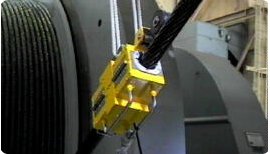
The equipment utilizes two strong magnets in a clam shell type set up to clamp around the rope. These magnets create a constant magnetic field in the steel rope. Since the magnetic field is constant, the amount of flux necessary to saturate the rope is a function of the cross-sectional area of the rope.
If the section of the rope that passes through the machine contains defects such as broken wires, corrosion thinning or stretching, the magnetic flux will be affected. These changes are interpreted on an oscilloscope display.
With proper calibration and training the technician can determine percentage of cross sectional loss, broken wires, and overall loss of break strength.
We Are Providing Ndt Inspection Services By Using Wire Rope Testing Equipment For All Steel Wire Rope Applications Like Bridge Incpection,Mining Industry,Cableway Inspection,Crane Inspection,Oil And Gas Industry, Shipping And Many More.
Laboratory LRM-NDE Perform The MRT ExaminationIn All Kinds Of Industries And All Available Diameters, Construction Of Wire Ropes With The Use Of LRM XXI Diagnostic System.
Extend the life of your crane’s wire ropes with our tensioning and electromagnetic inspection solution.Investing in new wire ropes can be a costly and time consuming exercise. Our ndt wire rope inspection services provides our clients with a service that allows them to confidently extend the life of their ropes and by in-situ condition based inspection.
By using this technique for wire rope inspection, clients gain real information about the condition of their ropes which leads to the potential of their life span being extended and in return reduces replacement costs.

Wire Rope Inspection Services in the oil and gas industry with the use ofLRM®XXI Diagnostic System allows to get information about the technical condition of wire rope in full cross section and in full available length of wire rope in the fastest way.
With regular periodic wire rope inspection combined with data utilization of crane the it is possible to estimate the remaining lifetime of crane wires.
Due to cooperation with Laboratory LRM-NDE with success offshore companies has implemented inspections of cranes wire ropes with the use of LRM®XXI Diagnostic System according to MRT Examination procedure and international standards for offshore fleet.
Long-term cooperation with offshore companies has allowed Laboratory LRM-NDE to achieve the knowledge and necessary competence to design wire rope diagnostic system equipment that can meet the harsh environmental conditions at sea.

Applus+ Velosi uses next generation Electromagnetic wire rope inspection technology EMAG to identify the internal condition of wire ropes. Our equipment can measure loss of metallic cross-sectional area (LMA) caused by external and internal corrosion, wear, broken wires, broken cores and deformations in steel wire ropes. The software used can also analyze the wire rope roughness (WRR) to produce a quantitative characterization of the internal broken wire clusters and corrosion pitting. We can also produce a conventional localized flaw (LF) signal that can help to detect broken wires and corrosion pitting. EMAG can offer cost efficiencies by reducing the need for periodic wire rope replacement, as well as eliminating an annual slip and cut policy.

As a kind of flexibility bearing component, steel wire ropes are applied widely. However, after being used for a period, some flaws may be produced in the steel wire rope. In order to ensure the safe operation of steel wire ropes, non-destructive testing methods are being applied to inspect steel wire ropes. In this paper, an intelligent non-destructive testing equipment, consisting of the sensing detectors and signal analysis computer system, has been designed and constructed. Any geometrical…Expand


 8613371530291