
non rotation vs rotation resistant wire rope free sample
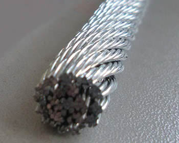
Rotation resistant wire rope refers to a series of steel ropes which minimizes the tendency to spin or rotation under load. These wire ropes boast special design - the outer layer is twisted in the reverse direction of inner layers for counteracting torsional forces generated from multi-layers of strands.
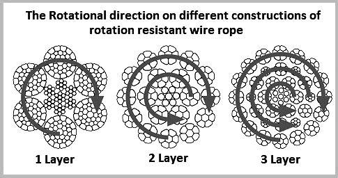
To achieve the resistance against the spin and rotation, all wire ropes are composed of at least two layers of strands. In general, more layers a rotation resistant wire rope has, more resistance it will boast. For example, 2-layer ropes is much easier to spin and rotate than 3-layer ones. Meanwhile, if one end of free rotation is allowed, 2-layer rope can only develop 55% to 75% of its breaking strength comparing with 95% to 100% of 3-layer ropes.
The 3-layer rope with more outer strands is capable to distribute more radial pressure onto inner layers and ideal for larger mobile such as all tower cranes.
Wire ropes with 8 to 10 strands & 2-layer constructions without reversely twisted inner strands have very similar appearance to rotation resistant wire ropes, but they are not.
Rotation resistant wire ropes are considered to be less stable needing to be handled and installed with great care. They must be taken to avoid high loads with small diameter sheaves.

Rope Services Direct supplies a variety of anti-spin non rotating wire rope (also called rotation resistant wire-rope). All standard rope wirehas a tendency to develop torque and therefore prone to rotation, whereas non-rotating wire ropes are designed so that the wire-rope outer rotational force naturally counteracts the inner strands rotational force. This is in the event that a rope is subjected to a load.
Rope elongation and rotation occurs on standard ropes when loaded, which can therefore spin the load, quite possibly out of control, which can be dangerous. When the rope rotates in this way the strands will begin to unravel. This causes the rope to lose strength and will undoubtedly fail, which could be catastrophic. It is for these reasons that non rotating wire rope is commonly used for many types of lifting applications including main hoist rope, whip rope,crane rope, off-shore and deck rope and more.
Non rotating wire rope or rotation resistant wire rope has a different construction to standard. as wires and strands are not laid in the same direction like they would be on standard rope. Inner and outer strands of wires are laid in opposite directions. For example the inner may be constructed in left hand lay whilst the outer layer is in right hand lay. The nature of this construction means that torsional forces on the inner and outer wires/strands will counteract each other and therefore minimising the risk of unraveling.
It is worth noting that the number of strand layers will have an effect of the resistance of rotation. A 2 layer rope has less resistance than a 3 layer rope. Therefore the more layers the rope has the greater rotation resistance it will have.
These types of ropes can be classified as spin resistant, rotation resistant or non rotation resistant. Classed on the basis of the number of rotations a certain length of rope does when a force of 20% of the MBF is applied; with 1 turn or less the rope will be classified as non rotating; with rotations between 1 & 4 the rope is classed as low rotation and for rotations between 4 & 10 the rope will be classified as spin resistant, any higher and the rope is NOT rotation resistant at all.
Correct usage and care with handling will prolong the working life. This is due to the friction on the inner wires caused by the strand crossover’s which will eventually cause the inner wires to break up. This is more apparent on non rotating wire rope with two layers. Ropes with 3 or more strand layers will distribute the radial pressures more evenly. Which will reduce friction and stress on the inner wires.
Regular,thorough inspectionsof non rotating rope are essential due to the fact that it is the inner strands that often break first and broken internal wires often go unnoticed as they are difficult to see.Rope Services Direct offer inspectionson all rope with certification issued on completion.
Holding both ends of the rope will prevent unraveling. Correctly fitted terminations will help to prevent damage. Kinking and unraveling may occur and they can also have an effect on the rotational balance if not fitted correctly.
Non-rotating wire ropes are designed so that the wire-rope outer rotational force naturally counteracts the inner strands rotational force in the event of a load applied.
Rather than all wires and strands being laid in the same direction, a rotation resistant wire rope consists of inner strands being laid in the opposite direction to the outer layers, for example the inner may be constructed in left hand lay whilst the outer layer is in right hand lay. This construction means that torsional forces on the inner and outer wires / strands will counteract each other and so minimise the risk of unraveling.
Using an ordinary lifting wire rope for a job or equipment which demand a non-rotating wire rope si very dangerous and it presents the following risks:

The characteristic of these wire ropes are that the outer layer is twisted in the opposite direction of their inner layers. The sometimes confusing issue is that many 8-, 9- and 10 strand constructions are 2-layer types but their inner strands are NOT twisted in the opposite direction and therefore these rope are NOT spin-resistant; plus, for the untrained eye these ropes look very much alike their spin-resistant variants. These and regular 6-strand ropes will spin violently and unlay themselves when loaded when one rope end is allowed to spin freely. They may also develop a significant drop in breaking strength and an even larger drop in their fatigue life characteristic (Torsion Fatigue).
To achieve any degree of resisting the tendency of a rope to spin and unlay under load all such rope types (other than 4-strand ones) are constructed with 2 or more layers of opposite twisted strands (see picture on right).
2-layer ropes (MULTI, COMPAC 18) have a larger tendency to rotate than 3-layer ones (e.g. Class 34 x 7, COMPAC® 35). Furthermore, 2-layer spin-resistant and rotation resistant ropes will develop only about 55% to 75% of their breaking strength when one end is allowed to rotate freely. This number increases to between 95% to 100% for 3-layer (e.g. COMPAC® 35) non-rotating ropes.
Another important issue is that 2-layer rotation resistant and 2-layer spin-resistant rope types have shown to break up from the inside. The 8 (e.g. 8×25 spin-resistant) or 12 outer strands (19×7, 19×19, COMPAC®18) are not able to evenly distribute the radial forces and because of the inherent internal strand cross overs (which make the rope spin- or rotation resistant) the resultant severe notching stresses cause the rope core to break up premature (unless the core is plastic coated, e.g. Python® Multi). Unexpected and sudden rope failures may be the result. Moreover, 2-layer spin-resistant or rotation resistant ropes satisfy only low to moderate rotational resistance demands.
3-layer rope constructions (e.g. COMPAC® 35) have many more outer strands which can much better distribute the radial pressures onto the reverse lay inner strands. These ropes should be selected for larger mobile- and ALL tower cranes.

The most important factor in selecting the right wire rope for the job in hand is deciding whether a rope type is to be rotation resistant or non-rotation resistant. This point needs to be considered very carefully as using the wrong rope type can have serious consequences, for example, shortened service life, changes in the rope structure, unintentional rope breaks.
Rotation resistant ropes must be used for the lifting of an unguided load on a single fall,the lifting of an unguided load on several falls at a great lifting height
Non-rotation resistant ropesmust be used for the lifting of a guided load,the lifting of unguided loads on several falls at low lifting heights,the lifting of loads with right-handed and lefthanded ropes operating in pairs, Non-rotation resistant ropes must not be used with a swivel.
The characteristic of these wire ropesare that the outer layer is twisted in the opposite direction of their inner layers. The sometimes confusing issue is that many 8-, 9- and 10 strand constructions are 2-layer types but their inner strands are NOT twisted in the opposite direction and therefore these rope are NOT spin-resistant; plus, for the untrained eye these ropes look very much alike their spin-resistant variants. These and regular 6-strand ropes will spin violently and unlay themselves when loaded when one rope end is allowed to spin freely. They may also develop a significant drop in breaking strength and an even larger drop in their fatigue life characteristic (Torsion Fatigue).
To achieve any degree of resisting the tendency of a rope to spin and unlay under load all such rope types (other than 4-strand ones) are constructed with 2 or more layers of opposite twisted strands (see picture on right).
2-layer ropes (MULTI, compacted 18xk7) have a larger tendency to rotate than 3-layer ones (e.g. Class 34 x 7, compacted 35WXK7). Furthermore, 2-layer spin-resistant and rotation resistant ropes will develop only about 55% to 75% of their breaking strength when one end is allowed to rotate freely. This number increases to between 95% to 100% for 3-layer (e.g. 35WXK7 compacted) non-rotating ropes.
Another important issue is that 2-layer rotation resistant and 2-layer spin-resistant rope types have shown to break up from the inside. The 8 (e.g. 8×25 spin-resistant) or 12 outer strands (19×7, 19×19, 18XK7) are not able to evenly distribute the radial forces and because of the inherent internal strand cross overs (which make the rope spin- or rotation resistant) the resultant severe notching stresses cause the rope core to break up premature (unless the core is plastic coated). Unexpected and sudden rope failures may be the result. Moreover, 2-layer spin-resistant or rotation resistant ropes satisfy only low to moderate rotational resistance demands.
3-layer rope constructions (e.g. compacted 35WXK7) have many more outer strands which can much better distribute the radial pressures onto the reverse lay inner strands. These ropes should be selected for larger mobile- and ALL tower cranes.
Non-rotating (non-rotational) wire ropes are used in various on and offshore cranes, various machinery, winches and trolleys, in the maritime and fisheries sector, on and offshore oil exploitation, civil and industrial construction, engineering and infrastructure works, underground and surface mining, timber mining and numerous other industries and applications.

Application: For port loading and unloading purposes, for tower crane purpose, lifting and drawing; the rope with steel core can be used under the shock load, heated and squeezed conditions such as excavator.
With advanced consciousness, brand-new concepts and innovative spirits, we integrate advanced technologies at home and abroad to continuously research and develop new Anti-Twist 19X7 Steel Wire Rope 16mm Rotation Resistant for Cranes for the industry. Enterprises in the development to form a good atmosphere, good rules, the majority of employees should consciously abide by the rules and disciplines. We promote the development of the company with innovative quality, and the scale of production is expanding year by year.

Wire rope is a complex mechanical device that has many moving parts, all working in tandem to help support and move an object or load. In the lifting and rigging industries, wire rope is attached to a crane or hoist and fitted with swivels, shackles or hooks to attach to a load and move it in a controlled matter. It can also be used to lift and lower elevators, or as a means of support for suspension bridges or towers.
A wire rope is a machine with many moving parts. It has a unique design consisting of steel wires that form individual strands laid in a helical pattern around a center core.
Wire rope is a preferred lifting device for many reasons. Its unique design consists of multiple steel wires that form individual strands laid in a helical pattern around a core. This structure provides strength, flexibility and the ability to handle bending stresses. Different configurations of the material, wire, and strand structure will provide different benefits for the specific lifting application, including:
However, selecting the proper wire rope for your lifting application requires some careful thought. Our goal is to help you understand the components of a wire rope, the construction of wire rope and the different types of wire rope and what they might be used for. This will allow you to select the best performing and longest-lasting wire rope for the job at hand.
A finished wire rope is comprised of individual wires, which make up individual strands, which are then laid in a helical pattern around a synthetic or steel core.
A wire rope is a machine with many moving parts. From childhood, many of us have been conditioned to think of a machine as some device with gears, shafts, belts, cams and assorted whirring parts. Yet, by the rules of physics, an ordinary pry bar is a simple machine, even though it has only one part.
A wire rope is, in reality, a very complicated machine. A typical 6 by 25 rope has 150 wires in its outer strands, all of which move independently and together in a very complicated pattern around the core as the rope bends. Clearances between wires and strands are balanced when a rope is designed so that proper bearing clearances will exist to permit internal movement and adjustment of wires and strands when the rope has to bend. These clearances will vary as bending occurs, but are of the same range as the clearances found in automobile engine bearings.
Understanding and accepting the “machine idea” gives a rope user a greater respect for rope, and enables them to obtain better performance and longer useful life from rope applications. Wire rope is a complex piece of mechanical machinery with a number of different specifications and properties that can affect its performance and service life.
A finished wire rope is comprised of individual wires, which make up individual strands, which are then laid in a helical pattern around a synthetic or steel core. There are four basic components that make up the design of a finished wire rope:
Wires are the smallest component of wire rope and they make up the individual strands in the rope. Wires can be made from a variety of metal materials including steel, iron, stainless steel, monel, and bronze. The wires can be manufactured in a variety of grades that relate to the strength, resistance to wear, fatigue resistance, corrosion resistance, and curve of the wire rope.
Strands of wire rope consist of two or more wires arranged and twisted in a specific arrangement. The individual strands are then laid in a helical pattern around the core of the rope. Strands made of larger diameter wires are more resistant to abrasion, while strands made of smaller diameter wires are more flexible.
The core of a wire rope runs through the center of the rope and supports the strands and helps to maintain their relative position under loading and bending stresses. Cores can be made from a number of different materials including natural or synthetic fibers and steel.
The construction of wire rope falls into one of these strand pattern classifications. The number of layers of wires, the number of wires per layer, and the size of the wires per layer all affect the strand pattern type. Wire rope can be constructed using one of the following patterns, or can be constructed using two or more of the patterns below.
Filler Wire – Two layers of uniform-size wire around a center with the inner layer having half the number of wires as the outer layer. Small filler wires, equal to the number in the inner layer, are laid in valleys of the inner wire.
Seale – Two layers of wires around a center with the same number of wires in each layer. All wires in each layer are the same diameter. The large outer wires rest in the valleys between the smaller inner wires.
Warrington – Two layers of wires around a center with one diameter of wire in the inner layer, and two diameters of wire alternating large and small in the outer later. The larger outer-layer wires rest in the valleys,and the smaller ones on the crowns of the inner layer.
Remember, wire rope is a complex piece of mechanical machinery. There are a number of different specifications and properties that can affect the performance and service life of wire rope. Consider the following when specifying the best type of wire rope for your lifting application:
When you select a piece of rope that is resistant to one property, you will most likely have a trade-off that affects another property. For example, a fiber core rope will be more flexible, but may have less crushing resistance. A rope with larger diameter wires will be more abrasion resistant, but will offer less fatigue resistance.
A rope with larger diameter wires will be more crush resistant and abrasion resistant, while a rope with smaller diameter wires will be more bendable and fatigue resistant.
On a preformed wire rope, the strands and wires are formed during the manufacturing process to the helical shape that they will take in a finished wire rope. Preformed rope can be advantageous in certain applications where it needs to spool more uniformly on a drum, needs greater flexibility, or requires more fatigue-resistance when bending.
Direction and type of lay refer to the way the wires are laid to form a strand (either right or left) and how the strands are laid around the core (regular lay, lang lay, or alternate lay).
Regular Lay – The wires line up with the axis of the rope. The direction of the wire lay in the strand is opposite to the direction of the strand lay. Regular lay ropes are more resistant to crushing forces, are more naturally rotation-resistant, and also spool better in a drum than lang lay ropes.
Lang Lay – The wires form an angle with the axis of the rope. The wire lay and strand lay around the core in the same direction. Lang Lay ropes have a greater fatigue-resistance and are more resistant to abrasion.
A steel core can be an independent wire rope or an individual strand. Steel cores are best suited for applications where a fiber core may not provide adequate support, or in an operating environment where temperatures could exceed 180° F.
The classifications of wire rope provide the total number of strands, as well as a nominal or exact number of wires in each strand. These are general classifications and may or may not reflect the actual construction of the strands. However, all wire ropes of the same size and wire grade in each classification will have the same strength and weight ratings and usually the same pricing.
Some types of wire rope, especially lang lay wire rope, are more susceptible to rotation when under load. Rotation resistant wire rope is designed to resist twisting, spinning, or rotating and can be used in a single line or multi-part system. Special care must be taken when handling, unreeling, and installing rotation resistant wire rope. Improper handling or spooling can introduce twist into the rope which can cause uncontrolled rotation.
Compacted strand wire rope is manufactured using strands that have been compacted, reducing the outer diameter of the entire strand, by means of passing through a die or rollers. This process occurs prior to closing of the rope.This process flattens the surface of the outer wires in the strand, but also increases the density of the strand. This results in a smoother outer surface and increases the strength compared to comparable round wire rope (comparing same diameter and classification), while also helping to extend the surface life due to increased wear resistance.
A swaged wire rope differs from a compacted strand wire rope, in that a swaged wire rope’s diameter is compacted, or reduced, by a rotary swager machine after the wire rope has been closed. A swaged wire rope can be manufactured using round or compacted strands.The advantages of a swaged wire rope are that they are more resistant to wear, have better crushing resistance, and high strength compared to a round strand wire rope of equal diameter and classification. However, a swaged wire rope may have less bending fatigue resistance.
A plastic coating can be applied to the exterior surface of a wire rope to provide protection against abrasion, wear, and other environmental factors that may cause corrosion. However, because you can’t see the individual strands and wires underneath the plastic coating, they can be difficult to inspect.
Plastic filled wire ropes are impregnated with a matrix of plastic where the internal spaces between the strands and wires are filled. Plastic filling helps to improve bending fatigue by reducing the wear internally and externally. Plastic filled wire ropes are used for demanding lifting applications.
This type of wire rope uses an Independent Wire Rope Core (IWRC) that is either filled with plastic or coated in plastic to reduce internal wear and increase bending fatigue life.

In selecting the right steel wire rope, it is important to determine how important the various properties are in relation to the application and then to assign priorities to these. It is also important to be aware of the relevant standards and regulations. If you are in any doubt, please contact our sales consultants or our Technical Department.
The tensile strength of the steel wire rope depends on the rope’s dimensions, the tensile strength of the wires and the construction. The minimum guaranteed tensile strength for the different kinds of rope is shown in the Randers Reb product catalogue.
The design of the steel wire rope does not significantly affect the tensile strength (up to approx. 5%). A change of core from fibre to steel makes slightly more difference (approx. 10%). The greatest change is achieved by changing the dimensions, usage of Compacted steel wire ropes or tensile strength of the wires (see also fig. 28).
It is often required that the steel wire rope must have a specific SWL value (Safe Working Load), also known as a WLL value (Working Load Limit). This means the steel wire rope’s tensile strength divided by the safety factor required for the relevant application.
Steel wire ropes with thick outer wires (e.g. 6x7 Standard or 6x19 Seale) provide good abrasion resistance. Lang lay ropes provide better abrasion resistance than regular lay steel wire ropes (see also fig. 28). Abrasion resistance can also be increased by using wires with greater tensile strength.
The greater the number of wires in the strand, the greater the bending fatique resistance and flexibility. Lang lay ropes provide better bending fatique resistance than regular lay steel wire ropes. Bending fatique resistance can also be increased by using pre-formed steel wire ropes (see also fig. 28).
Galvanised and rustproof wires provide excellent protection against corrosion. Lubrication with special types of grease or oil will also increase resistance to corrosion. If the steel wire rope is subjected to significant corrosive influences, it is recommended that strands with thick outer wires are used.
Steel wire ropes with fewer wires (e.g. 1x7 Standard and 1x19 Standard) are subject to the least elongation (have the greatest elasticity modulus). This type of steel wire rope is ideally suited for guy ropes, but is not suitable to be run over sheaves/blocks. If only a small degree of elongation when running over sheaves is required, 6x7 or 6x19 steel wire rope should be used, in each case with a steel core or with certain special constructions. For larger dimensions, 6x36 steel wire rope with a steel core can also be used (see also Elongation and Pre-stretching, page 8-28).
Standard 6-lay and 8-lay steel wire ropes will rotate when they hang free and carry a load. Regular lay steel wire rope provides greater resistance to rotation than lang lay steel wire rope. A steel wire rope with a steel core rotates less than a steel wire rope with a fibre core. The type of rope that provides greatest resistance to rotation is, as the name suggests, low-rotation and rotation-resistant steel wire rope (special constructions, see also ”Low-Rotation and Rotation-Resistant Steel Wire Rope”, page 8-10).
A steel core provides better support for the strands than a fibre core, which is why the risk of flattening is less in a steel wire rope with a steel core. Strands with fewer, thicker wires have greater resistance to flattening/crushing. Also, a 6-lay steel wire rope has greater crushing resistance than an 8-lay rope (see also fig. 28).
Vibrations, from wherever they might come, send shock waves through the steel wire rope, which will be absorbed by the steel wire rope at some point, and in some cases they may cause localised destruction of the steel wire rope (not necessarily on the outside). This may, for example, be at places where the steel wire rope comes into contact with a sheaf/block, or enters the drum, and by the end terminals. In general, those steel wire ropes with the greatest flexibility also have the greatest vibration resistance.
Changes in the tension of a steel wire rope, depending on the size and frequency, will reduce the rope’s life expectancy. In general, steel wire ropes with the greatest flexibility can cope better with intermittent loading. Great care should be taken in the use of end terminals or fittings, as their pulsation resistance is equally as important as the selection of the right steel wire rope.
Lang lay steel wire ropes are the ones most suited to running over sheaves and are the most durable, but if they are to be used, three things must be observed:
The reason for Lang lay steel wire ropes’ excellent qualities of abrasion resistance and pliability is that the wires are affected/loaded in a different way and have a larger load-bearing surface than a regular lay steel wire rope (see fig. 29). Note that the largest wearing surface is on the Lang lay steel wire rope.

EN12385-2 Steel wire ropes – Safety – Definitions, designation and classification provides a detailed explanation of all the terms and abbreviations used when describing a wire rope and its components. Below are a few of the most common abbreviations;
Steel wire ropes are specified in terms of a Nominal Rope Diameter and when produced have a manufacturing diameter tolerance, this tolerance can vary depending upon customer requirements and specifications and is often dictated by the diameter of grooving within sheaves and drums in which the wire rope will be expected to operate. If no diameter tolerance is specified, the general diameter tolerance is, Nominal Diameter +0% to +5% as specified within various International Rope Standards (EN12385-4, API-9A, ISO 2408). However, please note other diameter tolerances may be applied to ‘small’ diameter ropes and ropes used for specific applications/industries e.g. Mining, Aerials, Elevators, etc.
When designing any rope operated equipment, designers should consider the relevant National and/or International Standards which refer to acceptable sheave and drum diameters based upon the application, industry, etc. The diameter of sheaves and drums together with the tension, are normally associated with overall service life of the rope and in ‘simple terms’ the larger the diameter the longer the service life, although consideration should also be given to the anticipated modes of rope deterioration which will also significantly affect the service life. Typically, the diameter of sheaves and drums for crane applications are 16 to 28 times the nominal rope diameter.
Wire ropes are generally subjected to a visual examination and specifically for crane ropes these is an International Standard ISO 4309 “Cranes – Wire ropes – Care and maintenance, inspection and discard” which provides guidance on the inspection of wire ropes and provide the discard criteria. The document also includes information on the Magnetic testing of roper in service / Non-Destructive Examination and how this can assist the competent person in combination with his visual examination, determine the overall condition of the rope. All wire ropes should be inspected on a routine basis by a competent person to ensure that they remain is a good condition whilst in service and removed from service before they become dangerous. However, this standard is used for offering guidance for ropes operating in other systems where no specific discard criteria are given for that application, industry or country in which the rope is operating.
Please note, wire ropes can cause death and/or serious injury if not correctly handles, operated and maintained to good condition and care should always be taken when work with or close to wire ropes.
A new rope can easily be damaged if the pulley wheel groove is too tight, this will in effect pinch the rope probably causing a wave (spiral) deformity in your new rope.
If left unchecked in a steel pulley, parallel, linear fatigue wire breaks will be found where the contact pressures have become too high, due to a pinch affect.
The Lang’s construction, due to the wires running across the axis of the rope is the same direction as the strand, provides a greater length of wire on the exterior surface of the rope and hence since there is an increased surface area there is an increased area of steel to wear away before a broken wire occurs, therefore offering greater wear resistance. Therefore, applications where the rope is operating over larger number of support rollers and/or sheaves, the Lang’s lay rope may be of benefit.
The direction of the wires within the Lang’s lay construction also reduces the level of mechanical damage and rope interference, which takes place between adjacent wraps of rope within the crossover zones during multi-layer spooling of wire rope.
It is important to state that, single layer strand and parallel laid, rope constructions, manufactured in Lang’s lay, MUST NOT be used with one end free to rotate. Since the wires and the strands as twisted in the same direction, if the rope is free to rotate the wires and the strands will untwist tighter and seriously affect the integrity and breaking strength of the rope.
Wire ropes may be considered as machines, each with approximately 200 to 300 individual wires, which move independently to each over whenever ropes operate around sheaves or spool on or off winch drums, therefore ensuring ropes are lubricated internally will minimise the level of friction between the individual wires and optimise the ropes bend fatigue performance. Lubricant internally and externally will protect the ropes from corrosion and this applies equally to both un-galvanised/bright ropes and galvanised rope. Although the zinc on the surface of the individual wires of a galvanised rope will protect the wires from corrosion, once the zinc has sacrificed itself (oxidised) to protect the steel, the wires are then susceptible to corrosion. The longer the zinc can be protected by the lubricant the longer the zinc remains to offer protection to the steel. However there are applications where internal or external lubricant on the rope may not be advisable, anywhere the lubricant could drop off the rope and contaminate products (paper, food, etc.) in the vicinity of the rope or where the lubricant on the exterior of the rope may be contaminated with debris in the atmosphere (grit, sand, etc.). In this application, it must be accepted that ‘dry’ ropes will have a significantly reduced service life.
Ropes may be lubricated in-service with either oil or grease, both products offering slightly different benefits. Oils may be applied from a portable spray unit and although the ropes may require being re-lubricated more frequently, since it is relatively easy and cleaning to apply, operators are more likely to re-lubricate the ropes in service. The thin oil may penetrate the rope and surface coat the exterior of the rope with a thin film of lubricant, which also allows for relatively easy routine visual inspection of the rope. Alternatively, rope may be lubricated with a soft bearing type grease; the grease may be applied using a suitable pressure greasing system (Masto, Viper, etc.) to ensure uniform coating of grease along the total length of the rope passing through the greasing system, although the level and colour of grease may make visual inspection difficult. It is important that any oil or grease used to lubricate ropes in service is compatible with the lubricant applied to the rope during manufacturing and Bridon-Bekaert offer a range of wire rope lubricants specially formulated to be suitable for most environments and operations, including ECO VGP 2013 compliant (Bio-degradable, Non-toxic & Non-accumulative) products.
For ropes operating above ambient temperature consideration must be given to the effects the operating temperature may have on the wire rope. For guidance, unless otherwise stated, the maximum operating temperatures are provided in the International Standards e.g. EN 12385-3. However searches of these standards by Bridon-Bekaert indicate that the quoted temperatures within the standards have remained constant for a significant period of time, having been developed when rope constructions and usage centred around common 6-stranded rope constructions. With the introduction of more complex rope constructions incorporating higher tensile grade wires, synthetic lubricants and polymers, Bridon-Bekaert’s experiences indicate that reconsideration of the maximum operating temperatures is required. For high performance ropes incorporating synthetic lubricants and polymers Bridon-Bekaert recommend a maximum operating temperature of 100 degrees C. Excessive bleed out of lubricant from the rope may occur depending upon the rope operating temperature and the type/composition of the lubricant and frequent re-lubrication may be required.
Certain applications (Heave compensation systems, etc.) can generate high operating temperatures and for these and any application or where ropes are stored above ambient temperature, Bridon-Bekaert would be please to discuss this subject further.
Also due the smoothness of the circumference of these rope designs, they reduce wear at the cross over contact points as the rope wraps over itself as it is wound onto the drum.
An Ordinary lay rope is where the individual wires in the outer strands are spun / twisted together in the opposite direction to the direction the outer strands are twisted around the core, which results in the individual wires running along the axis of the rope. A Lang’s lay rope is where the individual wires in the outer stands are twisted in the same direction as the outer strands are twisted around the core, which results in the individual wires running across the rope in the same direction as the strands.
It is important to state that a left hand lay rope and a right hand lay rope MUST never be joined together unless the jointing mechanism is prevented from rotating, otherwise the rope will be allowed to un-twist together, which may have a significant effect on the integrity of the ropes, and could result in failure of the rope. There are two particular situations/arrangements where a left hand and/or right hand rope combination may be considered beneficial;
To prevent rotation of load – Twin rope operating systems (Overhead hoists, Grabbing systems, Container handling cranes, etc.) are generally designed to utilise one left hand rope and one right hand lay rope. When lifting a load both ropes will be subjected to an axial load and will try to un-twist, but since the ropes have been spun in different directions during manufacture one rope will trying to un-twist in one direction whilst the other rope will try to un-twist in the opposite direction, the two ropes therefore acting against each other to prevent/minimise rotation of the load.
When spooling a rope – Tension is generally applied to ropes whilst they are being spooled on to a winch drum and this tension will try to rotate / untwist the rope and therefore it is preferable to have the rope rotating up against the previous wrap of rope to minimise ‘gapping’ between the adjacent wrap of rope particularly on the bottom layer. Therefore, to achieve this, depending if the rope is anchored on the left or right hand side of the drum or the rope is being spooled under-wound or over-wound will determine if, a left or right hand lay rope should be utilised.
Rotation Resistant ropes are normally used to lift or suspend a load without the load rotating (example, hoist ropes used on Offshore, Mobile and Tower cranes, etc.) and are constructed by spinning the inner part of the rope in one direction and the outer part of the rope in the opposite direction. When an axial load is then applied to the rope the inner part will try to untwist in one direction and the outer part will try to untwist in the opposite direction, with the two parts of the rope reacting against each other. Rotation Resistant ropes are normally of a multi-strand construction and constructed of 2-layers of strands with the inner layer spun in the opposite direction to the outer layer and of 3-layers of strands with the inner two layers spun in the opposite direction to the outer layer. Three and four stranded rope constructions may also be considered as rotation resistant, but having only three or four strands, the ropes do not exhibit such a smooth exterior profile and may prove to be more difficult to spool, particularly when multi-layer spooled.
Wire rope does not have a defined shelf-live, provided the rope has been stored and maintained to ensure that the rope has not been allowed to deteriorate. To ensure that ropes remain in good condition, it is considered good practice to ensure the ropes are stored off the ground in a well-ventilated environment, protected from the sun, rain, sand/grit/dirt, chemicals or any other forms of contamination. Depending upon the environment the lubricant on the rope will tend to migrate to the bottom of the reel and dry out during storage. It is therefore good practice to rotate reels to prevent the lubricant migrating out of the rope on to the floor and to re-lubricate the ropes during storage by simple spraying a thin oil on to the surface of the rope to prevent the steel wires from corroding and/or zinc coating on the wires from oxidising (white rust). Whilst wire ropes are in storage they should be routinely inspected to ensure they have not been accidentally damaged, that all identification and certification remains in place and that the ropes remain fit for use. Rope being taken from storage on a ‘first in – first out’ basis, to minimise the length of time in storage.

The 6 x 19 classification of wire ropes includes standard 6 strand, round strand ropes with 16 through 26 wires per strand. The 6 x 36 classification of wire ropes includes standard 6 strand, round strand ropes with 27 through 49 wires per strand. Although their operating characteristics vary, all have the same weight per foot and the same nominal strength, size for size.
While the 6 x 19 ropes give primary emphasis to abrasion resistance in varying degrees, the 6 x 36 ropes are important for their fatigue resistance. This fatigue resistance is made possible by the greater number of small wires per strand.
Although there are exceptions for special applications, the constructions in 6 x 36 classification are primarily designed to be the most efficient for each rope diameter. As the rope size increases, for instance, a large number of wires can be used to achieve required fatigue resistance, and still those wires will be large enough to offer adequate resistance to abrasion.
In this construction, each strand has nine outer wires over nine smaller inner wires over one large center wire. A comparison of cross-sections shows that these outside wires are larger than those of the 6 x 25FW or 6 x 26WS. Therefore, its resistance to abrasion is increased, but its fatigue resistance is decreased. This is a good rope to withstand abrasion or crushing on the drum.
To most wire rope users, 6 x 19 means 6 x 25 filler wire. It is the most common rope in the 6 x 19 classification. This rope has a good balance between both abrasion resistance and fatigue resistance in relation to other ropes.
This construction has better resistance to abrasion than a 6 x 25FW. It also features a compact construction with solid support for the wires; hence, it has a high resistance to crushing. Its number and relative size of the inner wires add to the stability of the strand and gives it a fatigue resistance comparable to a 6 x 25FW.
A standard 6 x 26WS construction provides the best rope for a wide range of applications. In general, we recommend the use of a 6 x 26WS in any application where a 6 x 25FW is used.
In most rope sizes, only one 6 x 36 classification rope is made. These constructions were selected to provide fatigue resistance without having wires that are too small.
The greater number of wires in the 6 x 36 classification makes these ropes more susceptible to crushing. This can be minimized, however, by specifying an Independent Wire Rope Core (IWRC) and by using well-designed sheaves, grooved drums and proper operating techniques.
Rotation-resistant ropes can frequently provide the best and most economical service in specific applications when you choose, handle and use them properly.
Contra-helically laid, rotation-resistant ropes are different from standard ropes because they"re designed to reduce rope torque. Modes of failure and wear for rotation-resistant ropes can differ from those for standard rope constructions. The very nature of these ropes requires special handling, selection and usage not encountered with standard constructions. They are susceptible to kinking, crushing and unbalancing in the form of "core pops" and "birdcages" Use extreme care to avoid operational practices that can possibly lead to these conditions.
Rotation-resistant ropes should not be used with swivels that allow rope rotation -- or in single part lifts where the load can rotate. Rotation will cause a reduction in strength, unequal loading in the rope and possible rope unbalance. If any significant change in diameter is found in a short length of a rotation-resistant rope, the rope needs to be replaced.
These ropes should be replaced when you see two randomly distributed crown wire breaks in six rope diameters -- or four randomly distributed crown wire breaks in 30 rope diameters.
Because rotation-resistant ropes are special, there are separate design, maintenance, inspection and removal criteria established for them by applicable industry regulations and standards.
In an application where a single-part hoist rope is used to lift a free load -- or where rotation-resistant properties are essential for rope performance -- the 19 x 7 can be used. Its rotation-resistant characteristic is achieved by laying six strands around a core strand in one direction, then laying 12 strands around the first operation in the opposite direction. Thus, when the rope is in tension, opposing rotational forces are created between the inner and outer layers.
In addition, frequent and regular inspection for broken wires is critical when using this rope. Due to its design, the 19 x 7 construction has a relatively low reserve strength. This can result in short service life between the point in time when the broken wire removal criteria are met and when actual rope failure occurs.
In a multi-part wire rope system where the blocks have a tendency to twist -- or for a single-part hoist line that doesn"t require the degree of rotation-resistant properties found in a 19 x 7 rope -- the 8 x 25 Resistwist rope has found successful application. The rotation-resistant characteristic is achieved by laying the eight outer strands around an independent wire rope core so these strands are in the opposite direction to the lay of the core. Thus, when the rope is in tension, opposing rotational forces are created between the core and the outer strands.
Though not as rotation-resistant, the 8 x 25 Rotation Resistant rope is more stable than a 19 x 7 rope. It also has increased resistance to bending fatigue and crushing. This is achieved through the use of eight-strand construction with an independent wire rope core.
Like any application where an installation"s rope type is changed, the 8 x 25 Rotation Resistant rope should be substituted only after carefully comparing specifications and strength requirements.


 8613371530291