
non rotation vs rotation resistant wire rope made in china

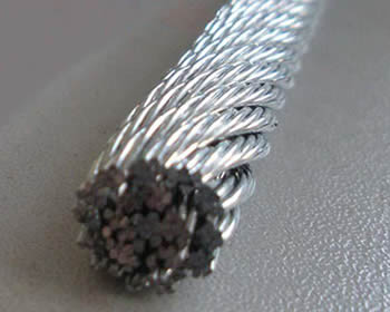
Rotation resistant wire rope refers to a series of steel ropes which minimizes the tendency to spin or rotation under load. These wire ropes boast special design - the outer layer is twisted in the reverse direction of inner layers for counteracting torsional forces generated from multi-layers of strands.
To achieve the resistance against the spin and rotation, all wire ropes are composed of at least two layers of strands. In general, more layers a rotation resistant wire rope has, more resistance it will boast. For example, 2-layer ropes is much easier to spin and rotate than 3-layer ones. Meanwhile, if one end of free rotation is allowed, 2-layer rope can only develop 55% to 75% of its breaking strength comparing with 95% to 100% of 3-layer ropes.
The 3-layer rope with more outer strands is capable to distribute more radial pressure onto inner layers and ideal for larger mobile such as all tower cranes.
Wire ropes with 8 to 10 strands & 2-layer constructions without reversely twisted inner strands have very similar appearance to rotation resistant wire ropes, but they are not.
Rotation resistant wire ropes are considered to be less stable needing to be handled and installed with great care. They must be taken to avoid high loads with small diameter sheaves.
The most important factor in selecting the right wire rope for the job in hand is deciding whether a rope type is to be rotation resistant or non-rotation resistant. This point needs to be considered very carefully as using the wrong rope type can have serious consequences, for example, shortened service life, changes in the rope structure, unintentional rope breaks.
Rotation resistant ropes must be used for the lifting of an unguided load on a single fall,the lifting of an unguided load on several falls at a great lifting height
Non-rotation resistant ropesmust be used for the lifting of a guided load,the lifting of unguided loads on several falls at low lifting heights,the lifting of loads with right-handed and lefthanded ropes operating in pairs, Non-rotation resistant ropes must not be used with a swivel.
The characteristic of these wire ropesare that the outer layer is twisted in the opposite direction of their inner layers. The sometimes confusing issue is that many 8-, 9- and 10 strand constructions are 2-layer types but their inner strands are NOT twisted in the opposite direction and therefore these rope are NOT spin-resistant; plus, for the untrained eye these ropes look very much alike their spin-resistant variants. These and regular 6-strand ropes will spin violently and unlay themselves when loaded when one rope end is allowed to spin freely. They may also develop a significant drop in breaking strength and an even larger drop in their fatigue life characteristic (Torsion Fatigue).
To achieve any degree of resisting the tendency of a rope to spin and unlay under load all such rope types (other than 4-strand ones) are constructed with 2 or more layers of opposite twisted strands (see picture on right).
2-layer ropes (MULTI, compacted 18xk7) have a larger tendency to rotate than 3-layer ones (e.g. Class 34 x 7, compacted 35WXK7). Furthermore, 2-layer spin-resistant and rotation resistant ropes will develop only about 55% to 75% of their breaking strength when one end is allowed to rotate freely. This number increases to between 95% to 100% for 3-layer (e.g. 35WXK7 compacted) non-rotating ropes.
Another important issue is that 2-layer rotation resistant and 2-layer spin-resistant rope types have shown to break up from the inside. The 8 (e.g. 8×25 spin-resistant) or 12 outer strands (19×7, 19×19, 18XK7) are not able to evenly distribute the radial forces and because of the inherent internal strand cross overs (which make the rope spin- or rotation resistant) the resultant severe notching stresses cause the rope core to break up premature (unless the core is plastic coated). Unexpected and sudden rope failures may be the result. Moreover, 2-layer spin-resistant or rotation resistant ropes satisfy only low to moderate rotational resistance demands.
3-layer rope constructions (e.g. compacted 35WXK7) have many more outer strands which can much better distribute the radial pressures onto the reverse lay inner strands. These ropes should be selected for larger mobile- and ALL tower cranes.
Non-rotating (non-rotational) wire ropes are used in various on and offshore cranes, various machinery, winches and trolleys, in the maritime and fisheries sector, on and offshore oil exploitation, civil and industrial construction, engineering and infrastructure works, underground and surface mining, timber mining and numerous other industries and applications.

The characteristic of these wire ropes are that the outer layer is twisted in the opposite direction of their inner layers. The sometimes confusing issue is that many 8-, 9- and 10 strand constructions are 2-layer types but their inner strands are NOT twisted in the opposite direction and therefore these rope are NOT spin-resistant; plus, for the untrained eye these ropes look very much alike their spin-resistant variants. These and regular 6-strand ropes will spin violently and unlay themselves when loaded when one rope end is allowed to spin freely. They may also develop a significant drop in breaking strength and an even larger drop in their fatigue life characteristic (Torsion Fatigue).
To achieve any degree of resisting the tendency of a rope to spin and unlay under load all such rope types (other than 4-strand ones) are constructed with 2 or more layers of opposite twisted strands (see picture on right).
2-layer ropes (MULTI, COMPAC 18) have a larger tendency to rotate than 3-layer ones (e.g. Class 34 x 7, COMPAC® 35). Furthermore, 2-layer spin-resistant and rotation resistant ropes will develop only about 55% to 75% of their breaking strength when one end is allowed to rotate freely. This number increases to between 95% to 100% for 3-layer (e.g. COMPAC® 35) non-rotating ropes.
Another important issue is that 2-layer rotation resistant and 2-layer spin-resistant rope types have shown to break up from the inside. The 8 (e.g. 8×25 spin-resistant) or 12 outer strands (19×7, 19×19, COMPAC®18) are not able to evenly distribute the radial forces and because of the inherent internal strand cross overs (which make the rope spin- or rotation resistant) the resultant severe notching stresses cause the rope core to break up premature (unless the core is plastic coated, e.g. Python® Multi). Unexpected and sudden rope failures may be the result. Moreover, 2-layer spin-resistant or rotation resistant ropes satisfy only low to moderate rotational resistance demands.
3-layer rope constructions (e.g. COMPAC® 35) have many more outer strands which can much better distribute the radial pressures onto the reverse lay inner strands. These ropes should be selected for larger mobile- and ALL tower cranes.

Rope Services Direct supplies a variety of anti-spin non rotating wire rope (also called rotation resistant wire-rope). All standard rope wirehas a tendency to develop torque and therefore prone to rotation, whereas non-rotating wire ropes are designed so that the wire-rope outer rotational force naturally counteracts the inner strands rotational force. This is in the event that a rope is subjected to a load.
Rope elongation and rotation occurs on standard ropes when loaded, which can therefore spin the load, quite possibly out of control, which can be dangerous. When the rope rotates in this way the strands will begin to unravel. This causes the rope to lose strength and will undoubtedly fail, which could be catastrophic. It is for these reasons that non rotating wire rope is commonly used for many types of lifting applications including main hoist rope, whip rope,crane rope, off-shore and deck rope and more.
Non rotating wire rope or rotation resistant wire rope has a different construction to standard. as wires and strands are not laid in the same direction like they would be on standard rope. Inner and outer strands of wires are laid in opposite directions. For example the inner may be constructed in left hand lay whilst the outer layer is in right hand lay. The nature of this construction means that torsional forces on the inner and outer wires/strands will counteract each other and therefore minimising the risk of unraveling.
It is worth noting that the number of strand layers will have an effect of the resistance of rotation. A 2 layer rope has less resistance than a 3 layer rope. Therefore the more layers the rope has the greater rotation resistance it will have.
These types of ropes can be classified as spin resistant, rotation resistant or non rotation resistant. Classed on the basis of the number of rotations a certain length of rope does when a force of 20% of the MBF is applied; with 1 turn or less the rope will be classified as non rotating; with rotations between 1 & 4 the rope is classed as low rotation and for rotations between 4 & 10 the rope will be classified as spin resistant, any higher and the rope is NOT rotation resistant at all.
Correct usage and care with handling will prolong the working life. This is due to the friction on the inner wires caused by the strand crossover’s which will eventually cause the inner wires to break up. This is more apparent on non rotating wire rope with two layers. Ropes with 3 or more strand layers will distribute the radial pressures more evenly. Which will reduce friction and stress on the inner wires.
Regular,thorough inspectionsof non rotating rope are essential due to the fact that it is the inner strands that often break first and broken internal wires often go unnoticed as they are difficult to see.Rope Services Direct offer inspectionson all rope with certification issued on completion.
Holding both ends of the rope will prevent unraveling. Correctly fitted terminations will help to prevent damage. Kinking and unraveling may occur and they can also have an effect on the rotational balance if not fitted correctly.

Original equipment wire rope and replacement wire rope must be selected and installed in accordance with the requirements of this section. Selection of replacement wire rope must be in accordance with the recommendations of the wire rope manufacturer, the equipment manufacturer, or a qualified person.
Wire rope design criteria: Wire rope (other than rotation resistant rope) must comply with either Option (1) or Option (2) of this section, as follows:
Option (1). Wire rope must comply with section 5-1.7.1 of ASME B30.5-2004 (incorporated by reference, see § 1926.6) except that section"s paragraph (c) must not apply.
Option (2). Wire rope must be designed to have, in relation to the equipment"s rated capacity, a sufficient minimum breaking force and design factor so that compliance with the applicable inspection provisions in § 1926.1413 will be an effective means of preventing sudden rope failure.
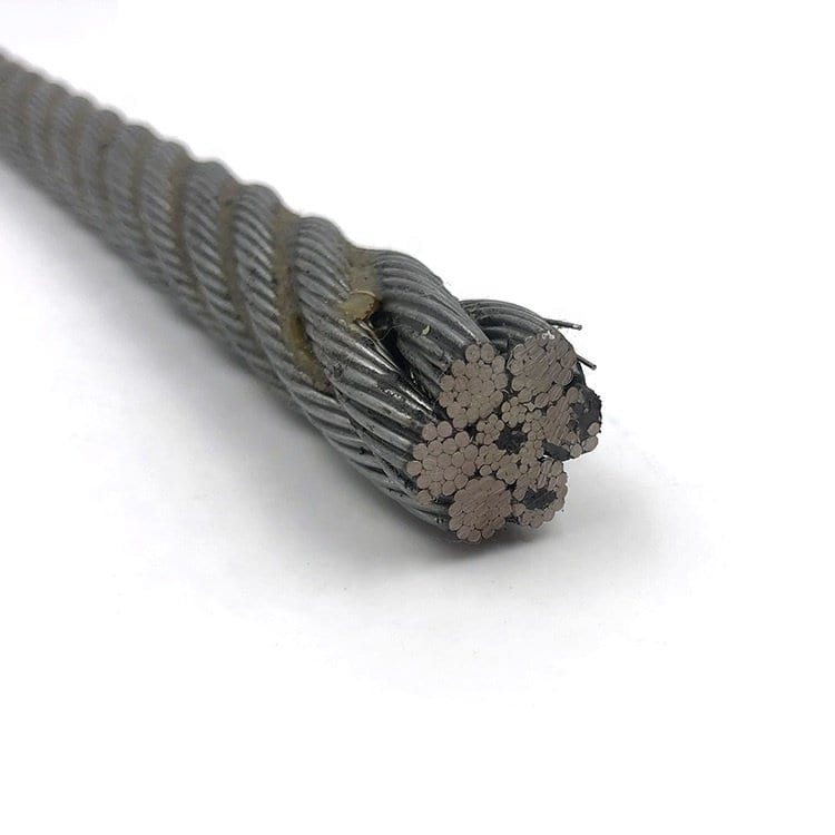
Type I rotation resistant wire rope ("Type I"). Type I rotation resistant rope is stranded rope constructed to have little or no tendency to rotate or, if guided, transmits little or no torque. It has at least 15 outer strands and comprises an assembly of at least three layers of strands laid helically over a center in two operations. The direction of lay of the outer strands is opposite to that of the underlying layer.
Type II rotation resistant wire rope ("Type II"). Type II rotation resistant rope is stranded rope constructed to have significant resistance to rotation. It has at least 10 outer strands and comprises an assembly of two or more layers of strands laid helically over a center in two or three operations. The direction of lay of the outer strands is opposite to that of the underlying layer.
Type III rotation resistant wire rope ("Type III"). Type III rotation resistant rope is stranded rope constructed to have limited resistance to rotation. It has no more than nine outer strands, and comprises an assembly of two layers of strands laid helically over a center in two operations. The direction of lay of the outer strands is opposite to that of the underlying layer.
Type I must have an operating design factor of no less than 5, except where the wire rope manufacturer and the equipment manufacturer approves the design factor, in writing.
When Types II and III with an operating design factor of less than 5 are used (for non-duty cycle, non-repetitive lifts), the following requirements must be met for each lifting operation:
A qualified person must inspect the rope in accordance with § 1926.1413(a). The rope must be used only if the qualified person determines that there are no deficiencies constituting a hazard. In making this determination, more than one broken wire in any one rope lay must be considered a hazard.
Each lift made under § 1926.1414(e)(3) must be recorded in the monthly and annual inspection documents. Such prior uses must be considered by the qualified person in determining whether to use the rope again.
Rotation resistant ropes may be used as boom hoist reeving when load hoists are used as boom hoists for attachments such as luffing attachments or boom and mast attachment systems. Under these conditions, all of the following requirements must be met:
The requirements in ASME B30.5-2004 sections 5-1.3.2(a), (a)(2) through (a)(4), (b) and (d) (incorporated by reference, see § 1926.6) except that the minimum pitch diameter for sheaves used in multiple rope reeving is 18 times the nominal diameter of the rope used (instead of the value of 16 specified in section 5-1.3.2(d)).
The operating design factor for these ropes must be the total minimum breaking force of all parts of rope in the system divided by the load imposed on the rope system when supporting the static weights of the structure and the load within the equipment"s rated capacity.
Wire rope clips used in conjunction with wedge sockets must be attached to the unloaded dead end of the rope only, except that the use of devices specifically designed for dead-ending rope in a wedge socket is permitted.
Prior to cutting a wire rope, seizings must be placed on each side of the point to be cut. The length and number of seizings must be in accordance with the wire rope manufacturer"s instructions.

Non-rotating wire ropes are made so that the outer rotational force of the wire rope naturally balances the rotational force of the inner strands. Standard rope wire has a tendency to create torque and is thus prone to rotation.
In the past, wrought iron chains, which had a history of mechanical failure, gave rise to wire rope. Defects in solid steel bars or chain links can result in catastrophic failure, whereas flaws in the wires that make up a steel cable are less important because the other wires can readily carry the strain. Although friction between the various wires and strands wears the rope over time, it also aids in temporary repair of minor flaws.
This pertains to the scenario in which a load is applied to a rope. In order to create a composite rope known as wire rope, numerous strands of metal wire are twisted into a helix in a pattern called lay rope. A larger diameter wire rope is made up of several strands of this lay rope arranged in a style called cable laid.
The global non rotating wire rope marketaccounted for $XX Billion in 2021 and is anticipated to reach $XX Billion by 2030, registering a CAGR of XX% from 2022 to 2030.
In terms of value, Regular Type of Lay is the fastest-growing Type of Lay for Steel Wires.Lang lay ropes spool poorly in a drum and are less naturally rotation-resistant and resistant to crushing forces than regular lay ropes.
They are employed in a variety of fields, including mining, oil and gas, construction, fishing, and marine. To address the unique wire rope needs of the new cranes, South Korean speciality high carbon steel wire products producer “Kiswire” is growing its operations in India. They not only serve as OEM suppliers to numerous global crane manufacturers, like Tadano and Kobelco, but they also actively pursue the Indian Replacement Market.

D07B2201/1056—Rope or cable structures twisted using alternate lay, i.e. the wires or filaments in the strands being oppositely inclined relative to the rope axis
The invention discloses an anti-rotation alternate lay wire rope comprising right-laid strands and left-laid strands. The wire rope is composed of the right-laid strands and the left-laid strands identical in number, the lay directions of the adjacent strand layers are opposite, in other words, the right-laid strands and the left-laid strands are arrayed alternatively, the up-down strand layer of any one of the right-laid strands is left-laid, and the up-down strand layer of any one of the left-laid strands is right-laid. The anti-rotation alternate lay wire rope has the advantages of regular lay wire ropes and Lang lay wire ropes, the strands in different directions are arrayed in the rope alternatively, the contact area of the wire rope is increased, mechanical property is better than that of the regular lay wire ropes and the Lang lay wire ropes, and mechanical property test and bonding strength test show that under the condition that same raw materials are selected, breaking force is increased by 12% as compared with that of the regular lay wire ropes of same specifications, and bonding strength with rubber is increased by 20% as compared with the regular lay wire ropes of the same specifications.
The breed structure of steel wire rope is a lot, traditional steel wire rope by the sth. made by twisting of left-hand lay and right-laid to being generally divided into ordinary lay and twist-on-twist two kinds.
Its rope of non-spinning wire rope, is twisted with the fingers to dividing sinistral coiling and a dextrad spiral to contrary (as shown in Figure 1) with the sth. made by twisting of stock.If rightlay rope is namely for be twisted into stock by steel wire rope by sinistral coiling, then make rope by stock to dextrad spiral turn.Because rope is contrary with reversing the trend of stock, cancel each other and there is no twist ties, loose trend, use more convenient, be mainly all kinds of lifting at present, elevation and subsidence mechanical adopts, but also have flexibility less, air spots is sliding, little with the contact area of pulley, to wear and tear shortcoming faster, cause using consume larger.
Its rope of Lang lay rope is twisted with the fingers to identical (as shown in Figure 2) with stock, and it is twisted with the fingers to being also divided into left and right sth. made by twisting, is twisted stock as right-laid is silk along wiring, and stock is twisted rope again and is dextrad spiral twisting and forms.The silk of this steel wire rope and the Contact of silk better, have good around property, that the life-span is long feature, but have twist ties, easily loose trend, can only be used for tensioned lines or pull rope, should not be used for lifting and winding rope.
Goal of the invention: for the deficiencies in the prior art, my company technique personnel, through repeatedly putting into practice improvement, devise a kind of anti-rotation alternatelaywirerope, the object that the twist stress reaching steel wire rope balances mutually, realize good anti-rotation effect.
Technical scheme: in order to realize foregoing invention object, the technical solution adopted in the present invention is: a kind of anti-rotation alternatelaywirerope, comprise right-laid and left-hand lay, described steel wire rope is made up of the identical right-laid of quantity and left-hand lay, the sth. made by twisting of each adjacent layer stock is on the contrary, namely described right-laid and left-hand lay are alternately arranged, and the levels stock of any right-laid is left-hand lay, and the levels stock of any left-hand lay is right-laid.
1, a kind of anti-rotation alternatelaywirerope of the present invention has the advantage of non-spinning wire rope and Lang lay rope, variantly to be alternately arranged in rope to stock, add the contact surface of steel wire, mechanical property also than non-spinning wire rope and Lang lay rope good, by to Mechanics Performance Testing of the present invention and adhesion test, select same materials, its performance change is as follows:
2, the present invention can substitute original left-hand lay wire rope and right-hand lay wire rope half and half completely, the situation that combination collocation uses.
As shown in Figure 1, the rope of non-spinning wire rope to the sth. made by twisting of stock to contrary, twist with the fingers to point sinistral coiling and a dextrad spiral.If rightlay rope is namely for be twisted into stock by steel wire rope by sinistral coiling, then make rope by stock to dextrad spiral turn.
As shown in Figure 2, the rope of Lang lay rope to the sth. made by twisting of stock to identical, it is twisted with the fingers to being also divided into left and right sth. made by twisting, is twisted stock as right-laid is silk along wiring, and stock is twisted rope again and is dextrad spiral twisting and forms.
As shown in Figure 3, a kind of anti-rotation alternatelaywirerope, comprise right-laid 1 and left-hand lay 2, described steel wire rope is made up of 3 bursts of right-laid 1 and 3 bursts of left-hand lays 2, and described right-laid 1 is alternately arranged with left-hand lay 2, i.e. the levels stock of any right-laid 1 is left-hand lay 2, the levels stock of any left-hand lay 2 is right-laid 1, the sth. made by twisting of each adjacent layer stock, on the contrary, makes the twist stress of stock mutually balance, reaches good anti-rotation effect.
1. an anti-rotation alternatelaywirerope, comprise right-laid (1) and left-hand lay (2), it is characterized in that: described steel wire rope is made up of the right-laid (1) of equal number and left-hand lay (2), described right-laid (1) and left-hand lay (2) are alternately arranged, namely the levels stock of any right-laid (1) is left-hand lay (2), and the levels stock of any left-hand lay (2) is right-laid (1).
Wire rope is commonly comprised of wire core and strand, which is made using various types of steel including galvanized, coated and non-coated. The steel wire ropes are also named as wire cables and steel wire, which are featured with high strength, flexibility, abrasion resistance, corrosion resistance and rotation resistance. This makes them well-suited for varieties of uses such as pulling, fixing and bearing in the marine, architectural and construction.
The wire ropes can be assembled into steel wire rope slings being used with lifting equipment or winches to meet lifting and rigging needs in different industries.
The wire ropes are classified according to the strand and wires. Shown below are just some typical types of wire ropes. Wire ropes are also available in customized constructions.
On 28th April 2017 Redaelli entered Teufelberger Group. Teufelberger and Redaelli both leading manufacturers of high performance steel wire ropes, unite their expertise to provide the best technical solutions for steel wire ropes and establish together a global presence.
We at Teufelberger-Redaelli understand your day-to-day challenges and solve them together with you. We develop and produce high performance steel wire ropes that create added value by enhancing the efficiency and safety of your applications. Expect more: of our innovative steel wire ropes, our services, our experienced experts in development, application engineering, and sales – all around the globe. Being a family enterprise, we attach great importance to successful, long-standing business relationships. Our commitment does not begin and end solely with the supply of premium quality steel wire ropes, but we also accompany you throughout your work processes when it comes to optimizing efficiency and costs.
We know that high performance steel wire ropes are able to unleash their full potential only if crane systems have been set up optimally and if the ropes have been installed correctly. Therefore, we also provide support during project planning, installation, and subsequent careful handling to maximize rope lifetimes. After all, the purchasing costs are just the tip of the iceberg.
Rotation-resistant and non-rotation-resistant high performance steel wire ropes from Teufelberger-Redaelli are used for a variety of applications such as:
Four manufacturing sites for steel wire ropes and a combined total of more than 425 years of rope-making experience tally up to a unique wealth of expertise and an unmatched and proven production standard. The resulting high degree of flexibility allows us to keep delivery times to a minimum.

Rope diameter is specified by the user and is generally given in the equipment manufacturer’s instruction manual accompanying the machine on which the rope is to be used.
Rope diameters are determined by measuring the circle that just touches the extreme outer limits of the strands— that is, the greatest dimension that can be measured with a pair of parallel-jawed calipers or machinist’s caliper square. A mistake could be made by measuring the smaller dimension.
The right way to unreel.To unreel wire rope from a heavy reel, place a shaft through the center and jack up the reel far enough to clear the floor and revolve easily. One person holds the end of the rope and walks a straight line away from the reel, taking the wire rope off the top of the reel. A second person regulates the speed of the turning reel by holding a wood block against the flange as a brake, taking care to keep slack from developing on the reel, as this can easily cause a kink in the rope. Lightweight reels can be properly unreeled using a vertical shaft; the same care should be taken to keep the rope taut.
The wrong way to unreel.If a reel of wire rope is laid on its flange with its axis vertical to the floor and the rope unreeled by throwing off the turns, spirals will occur and kinks are likely to form in the rope. Wire rope always should be handled in a way that neither twists nor unlays it. If handled in a careless manner, reverse bends and kinks can easily occur.
The right way to uncoil.There is only one correct way to uncoil wire rope. One person must hold the end of the rope while a second person rolls the coil along the floor, backing away. The rope is allowed to uncoil naturally with the lay, without spiraling or twisting. Always uncoil wire rope as shown.
The wrong way to uncoil.If a coil of wire rope is laid flat on the floor and uncoiled by pulling it straight off, spirals will occur and kinking is likely. Torsions are put into the rope by every loop that is pulled off, and the rope becomes twisted and unmanageable. Also, wire rope cannot be uncoiled like hemp rope. Pulling one end through the middle of the coil will only result in kinking.
Great stress has been placed on the care that should be taken to avoid kinks in wire rope. Kinks are places where the rope has been unintentionally bent to a permanent set. This happens where loops are pulled through by tension on the rope until the diameter of the loop is only a few inches. They also are caused by bending a rope around a sheave having too severe a radius. Wires in the strands at the kink are permanently damagedand will not give normal service, even after apparent “re-straightening.”
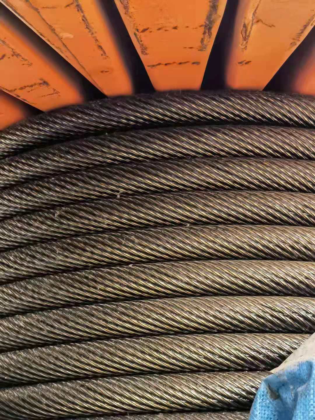
When wire rope is wound onto a sheave or drum, it should bend in the manner in which it was originally wound. This will avoid causing a reverse bend in the rope. Always wind wire rope from the top of the one reel onto the top of the other.Also acceptable, but less so, is re-reeling from the bottom of one reel to the bottom of another. Re-reeling also may be done with reels having their shafts vertical, but extreme care must be taken to ensure that the rope always remains taut. It should never be allowed to drop below the lower flange of the reel. A reel resting on the floor with its axis horizontal may also be rolled along the floor to unreel the rope.
Wire rope should be attached at the correct location on a flat or smooth-faced drum, so that the rope will spool evenly, with the turns lying snugly against each other in even layers. If wire rope is wound on a smooth-face drum in the wrong direction, the turns in the first layer of rope will tend to spread apart on the drum. This results in the second layer of rope wedging between the open coils, crushing and flattening the rope as successive layers are spooled.
A simple method of determining how a wire rope should be started on a drum. The observer stands behind the drum, with the rope coming towards him. Using the right hand for right-lay wire rope, and the left hand for left lay wire rope, the clenched fist denotes the drum, the extended index finger the oncoming rope.
Clips are usually spaced about six wire rope diameters apart to give adequate holding power. They should be tightened before the rope is placed under tension. After the load is placed on the rope, tighten the clips again to take care of any lessening in rope diameter caused by tension of the load. A wire rope thimble should be used in the eye of the loop to prevent kinking.
U-bolt Clips.There is only one correct method for attaching U-bolt clips to wire rope ends, as shown in TheRightWayimage below. The base of the clip bears on the live end of the rope; the “U” of the bolt bears on the dead end.
Compare this with the incorrect methods. Five of the six clips shown are incorrectly attached—only the center clip in the top view is correct. When the “U” of the clip bears on the live end of the rope, there is a possibility of the rope being cut or kinked, with subsequent failure.
Proper seizing and cutting operations are not difficult to perform, and they ensure that the wire rope will meet the user’s performance expectations. Proper seizings must be applied on both sides of the place where the cut is to be made. In a wire rope, carelessly or inadequately seized ends may become distorted and flattened, and the strands may loosen. Subsequently, when the rope is operated, there may be an uneven distribution of loads to the strands; a condition that will significantly shorten the life of the rope.
Either of the following seizing methods is acceptable. Method No. 1 is usually used on wire ropes over one inch in diameter. Method No. 2 applies to ropes one inch and under.
Method No. 1: Place one end of the seizing wire in the valley between two strands. Then turn its long end at right angles to the rope and closely and tightly wind the wire back over itself and the rope until the proper length of seizing has been applied. Twist the two ends of the wire together, and by alternately pulling and twisting, draw the seizing tight.
The Seizing Wire. The seizing wire should be soft or annealed wire or strand. Seizing wire diameter and the length of the seize will depend on the diameter of the wire rope. The length of the seizing should never be less than the diameter of the rope being seized.
Proper end seizing while cutting and installing, particularly on rotation-resistant ropes, is critical. Failure to adhere to simple precautionary measures may cause core slippage and loose strands, resulting in serious rope damage. Refer to the table below ("Suggested Seizing Wire Diameters") for established guidelines. If core protrusion occurs beyond the outer strands, or core retraction within the outer strands, cut the rope flush to allow for proper seizing of both the core and outer strands.
The majority of wire rope problems occurring during operation actually begin during installation, when the rope is at its greatest risk of being damaged. Proper installation procedures are vital in the protection and performance of wire rope products.
Until the rope is installed it should be stored on a rack, pallet or reel stand in a dry, well-ventilated storage shed or building. Tightly sealed and unheated structures should be avoided as condensation between rope strands may occur and cause corrosion problems. If site conditions demand outside storage, cover the rope with waterproof material and place the reel or coil on a support platform to keep it from coming directly in contact with the ground.
While lubrication is applied during the manufacturing process, the wire rope must still be protected by additional lubrication once it is installed. Lubricants will dry out over a period of time and corrosion from the elements will occur unless measures are taken to prevent this from happening. When the machine becomes idle for a period of time, apply a protective coating of lubricant to the wire rope. Moisture (dew, rain, and snow) trapped between strands and wires will create corrosion if the rope is unprotected. Also apply lubricant to each layer of wire rope on a drum because moisture trapped between layers will increase the likelihood of corrosion.
Always use the nominal diameter as specified by the equipment manufacturer. Using a smaller diameter rope will cause increased stresses on the rope and the probability of a critical failure is increased if the rated breaking strength does not match that of the specified diameter. Using a larger diameter rope leads to shorter service life as the rope is pinched in the sheave and drum grooves which were originally designed for a smaller diameter rope. Just as using a different diameter rope can create performance problems, so can the use of an excessively undersized or oversized rope.
Measure the wire rope using a parallel-jawed caliper as discussed in Measuring Rope Diameter at the top of this page. If the rope is the wrong size or outside the recommended tolerance, return the rope to the wire rope supplier. It is never recommended nor permitted by federal standards to operate cranes with the incorrect rope diameter. Doing so will affect the safety factor or reduce service life and damage the sheaves and drum. Note that in a grooved drum application, the pitch of the groove may be designed for the rope’s nominal diameter and not the actual diameter as permitted by federal standards.
Wire rope can be permanently damaged by improper unreeling or uncoiling practices. The majority of wire rope performance problems start here.Improper unreeling practices lead to premature rope replacement, hoisting problems and rope failure.
Place the payout reel as far away from the boom tip as is practical, moving away from the crane chassis. Never place the payout reel closer to the crane chassis than the boom point sheave. Doing so may introduce a reverse bend into the rope and cause spooling problems. Follow the guidelines highlighted under Unreeling and Uncoiling and Drum Winding. Take care to determine whether the wire rope will wind over or under the drum before proceeding. If the wire rope supplier secured the end of the rope to the reel by driving a nail through the strands, ask that in the future a U-bolt or other nondestructive tie-down method be used; nails used in this manner damage the rope.
Take extra precaution when installing lang lay, rotation-resistant, flattened strand or compacted ropes. Loss of twist must be avoided to prevent the strands from becoming loosened, causing looped wire problems.
The end of the rope must be securely and evenly attached to the drum anchorage point by the method recommended by the equipment manufacturer. Depending on the crane’s regulatory requirements, at least two to three wraps must remain on the drum as dead wraps when the rope is unwound during normal operations. Locate the dead end rope anchorage point on the drum in relation to the direction of the lay of the rope. Do not use an anchorage point that does not correspond with the rope lay. Mismatching rope lay and anchorage point will cause the wraps to spread apart from each other and allow the rope to cross over on the drum. Very gappy winding will occur resulting in crushing damage in multilayer applications.
Back tension must be continually applied to the payout reel and the crewman installing the rope must proceed at a slow and steady pace whether the drum is smooth or grooved.Regardless of the benefits of a grooved drum, tension must be applied to ensure proper spooling. An improperly installed rope on a grooved drum will wear just as quickly as an improperly installed rope on a smooth drum. If a wire rope is poorly wound and as a result jumps the grooves, it will be crushed and cut under operating load conditions where it crosses the grooves.
Every wrap on the first or foundation layer must be installed very tightly and be without gaps. Careless winding results in poor spooling and will eventually lead to short service life. The following layers of rope must lay in the grooves formed between adjacent turns of the preceding layer of rope. If any type of overwind or cross-winding occurs at this stage of installation and is not corrected immediately, poor spooling and crushing damage will occur.
On a multilayer spooling drum be sure that the last layer remains at least two rope diameters below the drum flange top. Do not use a longer length than is required because the excess wire rope will cause unnecessary crushing and may jump the flange. Loose wraps that occur at any time must be corrected immediately to prevent catastrophic rope failure.
The use of a mallet is acceptable to ensure tight wraps, however a steel-faced mallet should be covered with plastic or rubber to prevent damage to the rope wires and strands.
Rotation-resistant ropes of all constructions require extra care in handling to prevent rope damage during installation. The lay length of a rotation-resistant rope must not be disturbed during the various stages of installation. By introducing twist or torque into the rope, core slippage may occur—the outer strands become shorter in length, the core slips and protrudes from the rope. In this condition the outer strands become over- loaded because the core is no longer taking its designed share of the load. Conversely, when torque is removed from a rotation-resistant rope core slippage can also occur. The outer strands become longer and the inner layers or core become overloaded, reducing service life and causing rope failure.
The plain end of a wire rope must be properly secured. If the entire cross section of the rope is not firmly secured, core slippage may occur, causing the core to pull inside the rope’s end and allowing it to protrude elsewhere, either through the outer strands (popped core) or out the other end of the line. The outer layer of the outside strands may also become overloaded as there is no complete core-to-strand support.
Secure the ends of the rope with either seizing or welding methods as recommended under Seizing Wire Rope. It is imperative that the ends be held together tightly and uniformly throughout the entire installation procedure, including attaching the end through the wedge socket and the drum dead end wedge
When installing a new line, connect the old line to the new line by using a swivel-equipped cable snake or Chinese finger securely attached to the rope ends. The connection between the ropes during change-out must be very strong and prevent torque from the old rope being transferred into the new rope.Welding ropes together or using a cable snake without the benefit of a swivel increases the likelihood of introducing torque into the new rope. A swivel-equipped cable snake is not as easy as welding the ropes, but this procedure can be mastered with a little patience and practice.

Rotation rope and non-rotation rope or rotation resistant rope. Round strand rope, compacted rope, swaged rope. Wire rope with fiber core, wire rope with IWRC(Independent Wire Rope Core). Galvanized wire rope, ungalvanized wire rope or bright wire rope. Wire rope with plastic insert, Wire rope without plastic insert. Wire rope covered with plastic.


 8613371530291