
ordinary lay wire rope free sample
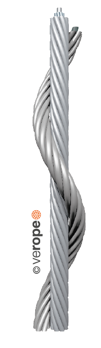
Left hand lay or right hand lay describe the manner in which the strands are laid to form the rope. To determine the lay of strands in the rope, a viewer looks at the rope as it points away from them. If the strands appear to turn in a clockwise direction, or like a right-hand thread, as the strands progress away from the viewer, the rope has a right hand lay. The picture of steel wire rope on this page shows a rope with right hand lay. If the strands appear to turn in an anti-clockwise direction, or like a left-hand thread, as the strands progress away from the viewer, the rope has a left hand lay. (The rope in the left hand lay photo shows one left hand lay rope from left to right and top to bottom, with 5 right hand lay strands, and part of a sixth in the upper left. It is not 5 right hand lay ropes adjacent to each other.)
Ordinary and Ducay"s lay describe the manner in which the wires are laid to form a strand of the wire rope. To determine which has been used, first identify if left or right hand lay has been used to make the rope. Then identify if a right or left hand lay has been used to twist the wires in each strand. (On ordinary lay, the outer wires approximately follow the alignment of the rope: with Lang"s lay they are cross at an angle of about 45�.) Lang"s laid rope is able to flex over sheaves more easily (with less damage) but it has the disadvantage of having a high torque tendency (it tends to untwist when tension load is applied) compared with ordinary laid rope. Untwisting can be dangerous with a steel-cored rope: load is shed from the strands and may cause the core to fail as it becomes higher loaded. For this reason, swivel termination units can be dangerous.
The specification of a wire rope type � including the number of wires per strand, the number of strands, and the lay of the rope � is documented using a commonly accepted coding system, consisting of a number of abbreviations.

Similar to regular lay, the right hand vs left hand is merely the way the wire rope closes with the strands in left hand lay rotating counterclockwise and right hand lay rotating clockwise. With lang lay rope, the wires in each strand lie in the same direction as the strands. When looking along a length of lang lay cable, the wires will appear to angle across the rope, following the general flow of the strands. Lang lay cables are more susceptible to pinching and kinking than regular lay, which best suits hoisting applications where the cable only moves along one axis. Lang lay is typically more flexible than regular lay. The third image down on the left is an example of right hand lang lay and the image below is left hand lang lay.
Now that you know about the differences and capabilities of each wire rope lay type, you can feel confident in purchasing the right lay for your wire rope applications! If you would like to check out our wire rope options, visit our website here. Alternatively, our team is happy to help if you have any questions! Reach out to us by email at sales@loosco.com or by phone at (860) 928-7981.

A distinction is made between the nominal rope diameter and the effective rope diameter. The nominal wire rope diameter is an agreed theoretical value for the diameter of the smallest circle circumscribing the outer strands.
The effective rope diameter, also called actual rope diameter, is the diameter of the smallest circle enclosing all outer strands, as measured on the rope itself. The tolerance range for the effective rope diameter is specified in related national and international standards. According to EN 12385-4 it is between -0{a889db705b9dbdba2a8d0dbcfc2b631547dc85af52ef75a70f044d2486ae0f02} and +5{a889db705b9dbdba2a8d0dbcfc2b631547dc85af52ef75a70f044d2486ae0f02} (for nominal rope diameters ≥ 8mm)
This means that the effective rope diameter upon delivery must neither be smaller nor bigger than 5{a889db705b9dbdba2a8d0dbcfc2b631547dc85af52ef75a70f044d2486ae0f02} than the nominal rope diameter. The tolerance range is often higher for smaller ropes like 3mm to 7mm nominal diameter. In the Oil and Gas industry, which is firmly based on US regulations, a tolerance range from -1{a889db705b9dbdba2a8d0dbcfc2b631547dc85af52ef75a70f044d2486ae0f02} to 4{a889db705b9dbdba2a8d0dbcfc2b631547dc85af52ef75a70f044d2486ae0f02} is applied. The effective rope diameter changes depending on the load applied. Therefore the effective rope diameter should in critical cases be measured on a rope that is loaded with 5{a889db705b9dbdba2a8d0dbcfc2b631547dc85af52ef75a70f044d2486ae0f02} of the calculated breaking strength. verope® produces standard tolerances of +2{a889db705b9dbdba2a8d0dbcfc2b631547dc85af52ef75a70f044d2486ae0f02} to +4{a889db705b9dbdba2a8d0dbcfc2b631547dc85af52ef75a70f044d2486ae0f02} and special tolerances upon request.
By the design of a wire rope, one understands the formation principle according to which the elements of the wire rope (the wires and the strands) are arranged relative to each other. The designation of a fiber core is FC, for an independent steel wire rope core it is IWRC. As an example all round strand ropes of the 6×19 Warrington design with a fiber core have the construction 6 x [1-6-(6-6)] – FC.
The fill factor of a rope is defined as the ratio of the metallic cross section of the rope (or a simplified calculation of the sum of the single wire cross sections) related to the nominal rope diameter. The fill factor specifies which amount of space the wires and strands take in the rope (figure 16).
The fill factors of the most common ropes are between 0,46 and 0,75. This means, that the amount of steel in the rope volume is about 46{a889db705b9dbdba2a8d0dbcfc2b631547dc85af52ef75a70f044d2486ae0f02} to 75{a889db705b9dbdba2a8d0dbcfc2b631547dc85af52ef75a70f044d2486ae0f02}. Wire ropes with a wire rope core have higher fill factors than ropes with a fiber core.
Usually fill factors of wire ropes with a fibre core (FC) decrease with an increasing number of outer strands. A rope of the design 6×25 Filler-FC has a fill factor of 0,50, a rope of the design 8×25 Filler-FC has only a fill factor of 0,445.
Usually fill factors of wire ropes with a wire rope core increase with an increasing number of outer strands. A rope of the design 6×25 Filler-IWRC has a fill factor of 0,58 and a rope of the design 8×25 Filler-IWRC has a fill factor of 0,587.
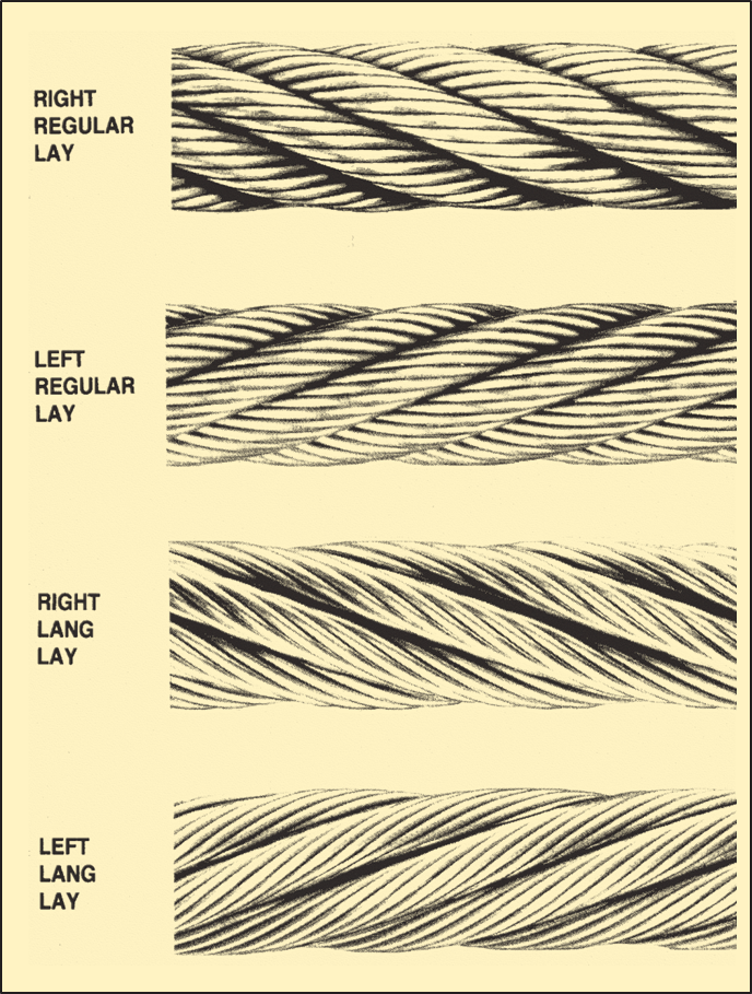
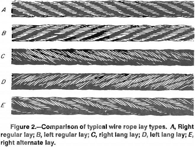
Two lay types are to be considered: Regular or ordinary lay and lang’s lay. In regular lay ropes, the lay direction of the wires in the strands is opposite to the lay direction of the strands in the rope. We distinguish between right hand ordinary lay RHOL (right hand strand, left hand rope, zS) (figure 17) and left hand ordinary lay LHOL (left hand strand, right hand rope, sZ) (figure 18). In lang’s lay ropes, the lay direction of the wires in the strands is equal to the strands in the rope. We distinguish between left hand lang’s lay LHLL (left hand strand, left hand rope, sS) (figure 19) and right hand lang’s lay RHLL (right hand strand, right hand rope, zZ) (figure 20).
In the stranding process the initially straight wires are forced into a helical or double-helical form. Therefore, the wires in a rope are always under tension, even in an unloaded rope. Such a rope must be sealed very tightly left and right of the joint before cutting the rope because otherwise the free ends of the wires will spring open. By using a “preforming tool”, the wires and strands can be heavily plastically deformed during the stranding, so are laying nearly without tension in the rope, the rope now is preformed. The ropemakers consider such ropes to be “dead”. Preformed ropes can be cut much easier, also secured by seizings of course, than nonpreformed ropes.
Usually wire ropes have either a fiber core (FC) or a steel/wire core. The steel/wire core can be a strand (WC) or a small rope, named as independent wire rope core (IWRC). The IWRC can be made in a separate operation or during the closing operation of the wire rope (PWRC). The wire core can also have a plastic coating (EPIWRC). Cores made of compacted strands have the additional designation (K). An independent wire core made of compacted strands is therefore called IWRC (K). A rope closed in a single operation and made out of compacted strands both in the core and the outer strands is called PWRC (K).
wire ropes and their free rope end rotate to a greater or lesser extent around its longitudinal axis under the influence of tension. Wire ropes having a core lay direction opposite to the lay direction of the outer strands and 3- or 4-strand regular lay wire ropes rotate considerably less than wire ropes with the same lay direction of the wire core and the outer strands and wire ropes with fiber cores. According to VDI 2358, a wire rope is semi rotation-resistant when: “the wire rope which turns around its longitudinal axis when subjected to unguided load and/or hardly transmits a torque to the attachment at the end in the event of guided rope ends.”
According to ISO 21669 and DIN EN 12385-3: “a rope is considered to be semi rotation resistant if it rotates at least once and at most four times around its axis at a length of 1000 x d under a load of 20 {a889db705b9dbdba2a8d0dbcfc2b631547dc85af52ef75a70f044d2486ae0f02} of the minimum breaking force. In terms of rotation angle, the defined limits are between 360° and 1440°.”
According to the regulation of VDI 2358, a wire rope is rotation-resistant, when: “the wire rope, which hardly turns around its longitudinal axis when subjected to unguided load and/or hardly transmits a torque to the attachment at the end in the event of guided rope ends.”
The wire rope lubricant has two major tasks: it should protect the rope from corrosion and minimize the friction between the rope elements themselves and between the rope and the sheave or the drum. A reduction of the friction reduces the actuating power and minimizes the wear of the rope, the sheaves and the drums. We differentiate between wax-based lubricants and oil-based lubricants. While wax-based lubricants offer a better handling of the ropes, the oil-based lubricants advantage is a better closing of the lubrication film due to the gravitational force of the oil. The quality of the wire rope lubricant has a great impact on the fatigue resistance of a wire rope (figure 22).
Regular laydenotes rope in which the wires are twisted in one direction, and the strands in the opposite direction to form the rope. The wires appear to run roughly parallel to the center line of the rope. Due to the difference in direction between the wires and strand, regular lay ropes are less likely to untwist or kink. Regular lay ropes are also less subject to failure from crushing and distortion because of the shorter length of exposed outer wires.
Lang layis the opposite; the wires and strands spiral in the same direction and appear to run at a diagonal to the center line of the rope. Due to the longer length of exposed outer wires, lang lay ropes have greater flexibility and abrasion resistance than do regular lay ropes. Greater care, however, must be exercised in handling and spooling lang lay ropes. These ropes are more likely to twist, kink and crush than regular lay ropes.
Right or left layrefers to the direction in which the strands rotate around the wire rope. If the strands rotate around the rope in a clockwise direction (as the threads do in a right hand bolt), the rope is said to be right lay. When the strands rotate in a counterclockwise direction (as the threads do in a left hand bolt), the rope is left lay.
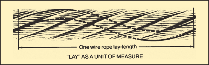
When a lay-length is used as a unit of measure, it refers to the linear distance a single strand extends in making one complete turn around the rope. Lay-length is measured in a straight line parallel to the center line of the rope, not by following the path of the strand. The appropriate time to replace a wire rope in service is frequently determined by counting the number of broken wires in the length of one rope lay.
Asteel wire rope is defined not only by its basic elements (wires, strands, core), but also by the way in which the individual wires are laid together to create a strand and the way in which the strands are laid around the core, etc. The steel wire rope’s construction is defined when the following criteria have been determined:
The steel wire rope is designated according to the number of strands, the number of wires in each strand, the design (type) of the strand, and the type of core.
The number of wires in a strand varies between three and approx. 139, although there are most commonly 7, 19, 24 or 36 wires. The number of wires and their thickness depend on the design of the strand and affects the characteristic of the steel wire rope.
The type of strand is characterised by the way in which the wires in the strand are arranged. There are four basic types of strand design that are used in all steel wire ropes, either in their original form or as a combination of two or more types. The four basic types are:
The Standard construction (fig. 3) is characterised by the fact that all wires are of equal thickness, although the core wire may be thicker. The wires are also laid together in such a way that all of them, with the exception of the centre wire, are of equal length. In this way all the wires are subjected to an equal distribution of load when pulled straight.
The geometric wire distribution consists of one centre wire, onto which one or more layers are laid. Each layer is produced in a separate operation. If there are several layers, the number of wires increases by six for each layer.
The designation for a Standard strand with e.g. seven wires is (1-6), i.e. one centre wire with six external wires in one operation. If there are 37 wires it is known as (1-6/12/18), i.e. one centre wire with six external wires from the first operation, 12 from the second operation and 18 from the third operation.
The Seale construction (fig. 5) is characterised by the way in which the strand consists of two layers of wire produced in one operation. Also, the number of wires in the first and second layer is identical.This construction is somewhat stiffer than a corresponding Standard construction (with the same number of wires). This is because the outer wires in the Seale construction are considerably thicker.
The Filler construction (fig. 7) is characterised by a strand consisting of two layers of wires produced in one operation. Also, the number of wires in the second layer is twice the number in the first layer. This is, however, only possible if filler wires are inserted between the first and the second layers, to prevent the strand becoming hexagonal in shapes.
This construction is more flexible than a corresponding Standard construction and considerably more flexible than a corresponding Seale construction (with the same number of wires excluding filler wires).
A Filler strand with e.g. 25 wires (including 6 filler wires) is known as (1-6+6F-12), i.e. one centre wire with six wires in the first layer and 12 wires in the second layer. There are six filler wires between the first and the second layers.
The Warrington construction (fig. 9) is characterised by a strand consisting of two layers of wire produced in one operation. The second (outer) layer contains wires of two dimensions, and the number of wires in the second layer is twice the number in the first.
This construction is very compact and flexible. A Warrington strand with e.g. 19 wires is known as (1-6-6+6), i.e. one centre wire with six wires in the first layer and a total of 12 wires of two dimensions in the second layer. The centre wire may be replaced by several wires or a fibre core (fig. 10).
The Warrington-Seale construction is characterised by a strand consisting of three layers of wire produced in one operation. The number of wires in the third (outer) layer matches the number of wires in the second layer. Also, the layers below the outer layer are built as a Warrington construction.
A Warrington-Seale strand with e.g. 36 wires is known as (1-7-7+7-14), i.e. one centre wire with seven wires in the first layer, 14 wires made up of two dimensions in the second layer, and 14 wires in the third layer.
The strands and the wires in the strands do not necessarily have to be round. Examples of this are shown in fig. 12. The strands are special strands (i.a. with profiled wire), designed to meet extremely unusual requirements.
The number of strands in a steel wire rope varies between three and approx. 36, although most commonly there are six strands. The more strands a steel wire rope contains, the more rounded and flexible it is, although the wires in the strand are also thinner (less durable).
Fibre cores are the most commonly used, as not only do they provide a good, elastic base but also enable lubrication of the rope from the inside, since it is possible to add oil and/or grease to the fibre core during production. This reduces the risk of rust attacking from the inside. The fibre core is normally produced from polypropylene (PP) or sisal. PP can withstand weaker acids and alkalis and it does not rot. The advantage of a sisal core is that it can absorb oil/grease to a greater degree for lubrication of the steel wire rope from the inside.
Randers Reb recommends the use of a steel core, in the event that it is not certain that a fibre core will provide satisfactory support for the strands, e.g. if thesteel wire rope is spooled on to a drum in several layers under a considerable load, or at high temperatures.
The word “lay” has more than one meaning in this context. It is used to describe the process of interweaving the wires and strands and also to describe the appearance of the finished steel wire rope. The four most common terms to describe the lay of a steel wire rope are:
Right hand regular lay steel wire rope. In this instance the wires in the strand are laid in the opposite direction to the strands in the rope. The wires are laid helically left, while the strands are laid helically right (see fig. 13).
Right hand Lang lay steel wire rope. Here the wires are laid in the same direction as the strands in the rope. The wires in the strands and the strands are laid helically right (see fig. 15).
Multi layer steel wire rope (low rotation/rotation resistant). Here there are usually two layers of strands, the inner layer as a rule a left hand Lang lay, while the outer layer is a right hand regular lay.
Cable laid steel wire rope. The strands are normally 6-lay steel wire rope with a fibre or steel core. The core is a fibre core or a 6-lay steel wire rope with a fibre or steel core.
Flat braided steel wire rope. This steel wire rope is flat braided from strands or consists of parallel strands or steel wire ropes that are bound together by sewing (belt strap).
Right hand lay steel wire rope is also known as Z-lay, and left hand as S-lay. Similarly, a right hand lay strand is known as z-lay and left hand as s-lay. Fig. 17 shows why. Of the types of lay described, right hand regular lay is the most common.
“Preformed” refers to steel wire ropes in which the strands have been permanently formed during the laying process (see fig. 18), so that they are completely stress-free within the unloaded steel wire rope.
All Randers Reb steel wire ropes are supplied preformed, with the exception of certain individual special constructions (e.g. low-rotation/rotation resistant).

Rope Services Direct supplies a variety of anti-spin non rotating wire rope (also called rotation resistant wire-rope). All standard rope wirehas a tendency to develop torque and therefore prone to rotation, whereas non-rotating wire ropes are designed so that the wire-rope outer rotational force naturally counteracts the inner strands rotational force. This is in the event that a rope is subjected to a load.
Rope elongation and rotation occurs on standard ropes when loaded, which can therefore spin the load, quite possibly out of control, which can be dangerous. When the rope rotates in this way the strands will begin to unravel. This causes the rope to lose strength and will undoubtedly fail, which could be catastrophic. It is for these reasons that non rotating wire rope is commonly used for many types of lifting applications including main hoist rope, whip rope,crane rope, off-shore and deck rope and more.
Non rotating wire rope or rotation resistant wire rope has a different construction to standard. as wires and strands are not laid in the same direction like they would be on standard rope. Inner and outer strands of wires are laid in opposite directions. For example the inner may be constructed in left hand lay whilst the outer layer is in right hand lay. The nature of this construction means that torsional forces on the inner and outer wires/strands will counteract each other and therefore minimising the risk of unraveling.
It is worth noting that the number of strand layers will have an effect of the resistance of rotation. A 2 layer rope has less resistance than a 3 layer rope. Therefore the more layers the rope has the greater rotation resistance it will have.
These types of ropes can be classified as spin resistant, rotation resistant or non rotation resistant. Classed on the basis of the number of rotations a certain length of rope does when a force of 20% of the MBF is applied; with 1 turn or less the rope will be classified as non rotating; with rotations between 1 & 4 the rope is classed as low rotation and for rotations between 4 & 10 the rope will be classified as spin resistant, any higher and the rope is NOT rotation resistant at all.
Correct usage and care with handling will prolong the working life. This is due to the friction on the inner wires caused by the strand crossover’s which will eventually cause the inner wires to break up. This is more apparent on non rotating wire rope with two layers. Ropes with 3 or more strand layers will distribute the radial pressures more evenly. Which will reduce friction and stress on the inner wires.
Regular,thorough inspectionsof non rotating rope are essential due to the fact that it is the inner strands that often break first and broken internal wires often go unnoticed as they are difficult to see.Rope Services Direct offer inspectionson all rope with certification issued on completion.
Holding both ends of the rope will prevent unraveling. Correctly fitted terminations will help to prevent damage. Kinking and unraveling may occur and they can also have an effect on the rotational balance if not fitted correctly.
A wire rope serves as a flexible tackle to transmit pulling force over a distance, to perform hauling, hoisting or suspending operation. Wire ropes and slings find variety of applications in engineering industries, construction and material handling. Information about reasons for use of wire ropes, components of a wire rope, construction of wire ropes, strand patterns, lay and lay selection and wire rope manufacturing process is given in this article.
Wire ropes are designed to transmit forces longitudinally along their axis. The reasons for use of wire ropes lie in their three main properties as under.
A typical wire rope may contain hundreds of individual wires which are formed and fabricated to move or operate at close bearing tolerances with respect to one another. When a wire rope bends, each of its many wires slides and adjusts in the bend to accommodate the difference in length between the inside and the outside bend. Due to this flexibility, it can be wound on reels or packed in coils resulting into easier storing and transportation. Secondly during use, it can be wound on drums and deflected over sheaves or rollers to change the direction of imparted forces.
Safety and dependability of wire ropes are mainly due to its construction in that it consists of many members. Under usual conditions wire ropes give a warning before possible failure by the progressive development of broken wires which can be easily detected by proper inspection. It is therefore possible to replace a wire rope before any unsafe condition is reached. Failure of tensile members such as single wire or rod or linkages of solid units usually takes place instantaneously and completely without any prior warning.
A wire rope is generally made up of number of strands twisted around a core. The strands are themselves formed from a number of wires twisted in a helical fashion.
The wires are predominantly constructed from high-carbon steel, but may also be formed from various metals such as stainless steel, monel or bronze. High-carbon steel wires come in various grades. The term "Grade" is used to designate the strength of the wire rope. Wire ropes are usually made of Improved Plow Steel (IPS), Extra Improved Plow Steel (EIPS) or Extra Extra Improved Plow Steel (EEIPS).
The main function of the core in a wire rope is to serve as a seat for the strands, providing sufficient support and to keep them in their proper position throughout the life of the rope. It is also an effective lubricant carrier. There are two types of core; one is made of fibre and another of wire.
Fibre cores are mainly manufactured from a natural fibre, either manila, sisal or hemp. Present day condition of operation subject a wire rope to severe pressures, and as fibre core ropes will not withstand these condition, their use is restricted to conditions where the loading is light. Some fibre cores are manufactured from polypropylene or nylon but the use of synthetic fibre cores has been confined to a few types of service where they are able to stand up to chemical agents which would attack a natural fibre.
Cores made from wire are usually a small wire rope of suitable size to serve as a core. This is called an independent wire rope core, usually referred to as IWRC. The other type of wire core is a wire strand structure. It is called a strand core and usually abbreviated as WSS (wire strand structure) or WSC (wire strand core). The IWRC is preferred as a core where resistance to crushing or heat is required.
The number of wires per strand. Frequently, in the case of Flattened Strand, the number of wires in each layer of the strand is detailed and in Round Strand, the make-up is named, e.g. Seale, Filler, and Warrington.
In Filler Construction the number of filler wires added to a layer of ordinary wires is indicated by the plus sign “+“ followed by capital letter “F“.
6X18/6 and 6/6/1 = A rope of 6 strands, each strand consisting of a layer of 18 wires over a layer comprising of 6 large and 6 small wires over a layer of 6 wires over 1 wire.
In this design, strands are made in more than one operation (For example, 19 wire strand is produced in two operations. In first operation, single layer strand is made. Another layer of 12 outer wires is laid on the first layer in the second operation.). The layers are formed one over the other in succession.
If wires of equal size are used in all layers, it will be necessary to change the lay (or pitch) of the covering layer to that of the covered layer so that the wires would fit in smoothly and the wires will be cross laid. If wires are to be laid parallel (having same length of lay in all layers), different size of wires will be required in different layers (as in seale or warrington strand) or filler wires will be required to be filled in between the two layers (as in filler strand).
In this design, the outer layer has a predetermined number of large wires. They are laid around an equal number of small inner wires in such a manner that the outer wires lie in the valley of the under lying wires. The advantage of this form is in its more abrasive surface.
In this design, a layer of pairs of wires (one large and one small) is laid over an inner layer of wires. The number of wires in the inner layer is half of those in the outer layer. In this formation the strand is more roundish. It has more wearing surface without losing flexibility.
In many compound constructions, when there are more than two layers of wire over the centre wire, a combination of any two from among Filler, Seale and Warrington is designed.
In the Warrington Seale construction shown in above figure, the intermediate layer has a Warrington relationship with the inner layer and a Seal relationship with the outer.
The cores of the strands of a flattened strand rope may consist of one or more triangular wire or three or more round wires. The strands may be triangular or oval.
Above picture shows cross section of a triangular strand. Three round wires are forming core of the strand. Flattened strand have greater surface area of steel. The Flattened Strand rope have about 15% greater cross sectional metallic area, hence they are stronger and have longer life. They are mainly used in the mining industry as haulage rope.
If a strand is made by compacting wires, it is called compact strand. To make compact strands, ready made strands are forced through a series of rollers which compress the strand and shape the individual wires to have a flat outer surface.
Above figure shows cross section of a 6X26 (1/5/5+5/10) Warrington – Seale pattern compact strand wire rope. The compacting process provides increased strength and durability. The smooth surface inherently provides a high resistance to abrasion and crushing improving service life of the rope.
This process is usually applied to wire ropes with plastic coated core. This process is applied after the rope has been manufactured and compresses the entire rope circumference. Due to the process, individual surface wires are shaped flat and strand gaps are closed. The process transforms the entire rope into a more "round" shape as shown below (pictures of strand compaction is also given for comparison).
When loaded, steel wire rope generates torque at ends if both ends are fixed and turns if one end is unrestrained (for example anchored using a swivel). Rotation Resistant ropes ensure that problems associated with load rotation are minimized. Rotation resistant ropes are constructed with 2 or more layers of opposite twisted strands
Above figure shows19X7 wire rope designed to resist the tendency to spin or rotate under load. This is achieved by laying 6 strands around the core in one direction and then laying 12 strands around the first layer in another direction. If outer strands are NOT twisted in the opposite direction, the rope will not be rotation resistant. They are often used for hoisting unguided loads with a single part rope.
Two layer ropes have a larger tendency to rotate than three layer ones (e.g. class 34×7). Furthermore, two layer rotation resistant ropes will develop only about 55% to 75% of their breaking strength when one end is allowed to rotate freely. This number increases to between 95% to 100% for three layer rotation resistant ropes.
These ropes have a smooth cylindrical surface. The outer wires of the rope are drawn to such shape that each one interlocks with its adjacent wire. The wires are disposed in concentric layers above a wire core instead of strands. They are used for material handling and mining application.
Each strand in a wire rope is helical in shape. The distance measured parallel to the axis or the centre line of a rope in which the strand makes one complete spiral around the rope is the length of rope lay.
This term refers to the direction in which the strands are laid up in the rope. Left hand lay or right hand lay describe the manner in which the strands are laid to form the rope. To determine the lay of strands in the rope, a viewer looks at the rope as it points away from them. If the strands appear to turn in a clockwise direction, or like a right hand thread, as the strands progress away from the viewer, the rope has a right hand lay. The above picture of steel wire rope shows a rope with right hand lay. If the strands appear to turn in an anti-clockwise direction, or like a left hand thread, as the strands progress away from the viewer, the rope has a left hand lay.
In regular lay wires in each strand is in the opposite direction to the lay of the strands that form the rope. It is also known as ordinary lay. The wires in regular lay rope appear to be in line with the axis of the rope.
Cross laid construction is usually one size wire construction where all the wires, except the King or Centre Wire, are of the same diameter. In the stranding operation each covering layer is provided with a longer lay (or pitch) than the underlaid layer of wires. Therefore, in cross laid ropes, the wires in the covering layer, although spiraling in the same direction as the wires in the underlaid, will repeatedly cross over the inner wires.
The equal (parallel) laid principle is to make each covering layer of wires to the same length of lay as the underlying layer, thereby eliminating any crossing of the wires in these strands. Seale, Filler and Warrington strand forms are examples of equal laid principle.
A standard wire rope is a right hand regular lay rope composed of six strands laid around a core. All ropes are supplied with this lay unless otherwise specified.
Left hand regular lay ropes are used where drum and anchorages are such that right lay ropes wound under load would tend to roll away from adjacent laps, resulting in uneven winding. They are also used to counter the rotation of a right hand lay rope when two ropes are used as a pair. Usually, a left hand lay rope is used in combination with a right hand lay rope. Left hand lay is also used in ropes for drilling purposes to prevent unscrewing of rods.
Lang’s lay ropes are used in construction and mining applications. It is more flexible and has greater abrasion resistance due to longer length of wire exposed to wear than ordinary lay rope. Since Lang’s lay ropes have little resistance within themselves (to unlaying) on account of the wires and strands being laid in the same direction, they should not be used where the load is suspended from a free end and allowing the rope to rotate. When a Lang’s lay rope is unwound care should be taken since it has got tendency of unlaying.
A six strand wire rope in which three strands are ordinary lay and three strands are Lang’s lay is known as alternate lay wire rope and combines some desirable properties of both the regular lay and the Lang’s lay type of rope.
The use of equal (parallel) lay strands avoids deformation, internal wear and secondary bending which results from the point of contact between the wires in a cross laid strand. In most fields of application, therefore, equal lay ropes have proved to have a longer life than cross laid ropes.
Steel wire ropes are made from high carbon Steel rods. Patenting is a heat treatment process. In patenting wire rods are heat treated above their transformation temperature. Due to this they attain a homogeneous granular structure.
After patenting oxide forms on the surface of rod / wire. This oxide is removed from rod/wire by immersing them in a tank of cold hydrochloric acid, rinsing thoroughly with a jet of water, and finally covering the surface with a layer of protective phosphate coating.
It is a cold process involving plastic deformation of steel. In drawing, preheated and pickled rod is cold drawn through a series of successively smaller, accurately shaped and polished dies. After drawing, the material now in wire form acquires its final mechanical properties, shape and size
Galvanizing is a means of protecting steel against corrosion by coating it with Zinc (spelter). The coating of Zinc is normally applied by the Hot Dip process or by electro-depositing. In Hot Dip process the finished drawn wire is passed through a bath of molten zinc. Galvanized wires made by Hot Dip process are not suitable for high tensile strength application as the bath temperature is sufficiently high to alter the physical and mechanical characteristics. In coating by Hot Dip or electro-depositing, the coating of spelter on wire tends to be porous and also liable to cracking or flaking.
If high tensile strength is required, wires are drawn after galvanizing. They are called "Drawn Galvanized". Due to drawing after coating, the spelter becomes more homogeneous and is bonded to the steel much more firmly. This method produces wires having desirable properties of a bright wire (uncoated wires are called "bright" or "black") with a corrosion resisting Zinc coat.
Standing ropes, such as rigging for ships, guy ropes, bridge ropes, etc., which are exposed to the atmosphere and often a corrosive atmosphere, are normally galvanized, or fully galvanized, i.e. made from wires in the state it comes from the galvanizing process without further treatment. This ensures a heavy coating of spelter and gives maximum protection.
On operative ropes, however, such as hoisting ropes, crane ropes, etc., Drawn Galvanized wires are used. The wire used in the manufacture of the rope in this instant is drawn after the wire is galvanized. This reduces to a degree the amount of spelter per sq. mm. of wire but bonds the spelter to the wire more firmly than in the case of fully galvanized wire. This is essential when the rope is working over pulleys or drums.
Performing is the process in which each individual strand and each individual wire is permanently formed (shaped or set) during fabrication process in the helical shape it will assume in the finished wire rope. This process causes the strands to lie in place and removes the tendency of wires and strands to fly apart when cut. As performed rope is more inert than non performed rope, it is easier to handle during installation and is less susceptible to the formation of kinks. It can be put to work at full capacity after a shorter “running in” period.
Outer wires of preformed ropes after breaking do not protrude from the rope to injure workmen’s hands, do not distort adjacent wires or cause excessive wear to sheaves and drums.
When required, ropes are subjected to postforming in addition to the aforesaid performing process, where the residual stress resulting out of the stranding and closing operations are minimized and the rope becomes “dead”.
Wire ropes for certain uses as in suspension bridge should not elongate while in use. So, after manufacture, the whole length of the wire rope is per-stretched to prevent further elongation. This is done by fixing the ends of the wire rope at two terminal and applying safe working load for a certain period of time as per specification. As a result of this, the structural and elastic stretch that may arise during the valuable life of the rope is done away with.
Lubrication of ropes serves a double purpose. Firstly the lubrication resists corrosion and secondly, it enables the wires to move in smoothly resulting in less wear.
During the process of manufacture the strands of the core are well lubricated. In case of ropes for general use the fibre core is thoroughly impregnated with suitable lubricants which prevent the fibre core from wroughting and also act as a preservative of lubricant providing internal lubrication.
Finally, the rope itself is passed through a bath of a special wire rope dressing compound which thoroughly lubricates the rope and also leaves a thin film of lubricant on the surface of the wire rope. The rope thus lubricated, permits strands and wires to move smoothly and is preserved against corrosion during the time of transport and storage.
For quality control, testing is carried out at various stages of manufacturing like raw material testing, testing for thickness of Zinc coating after galvanizing, testing of finished wires for shape and size (diameter, roundness in case of round wires, and smoothness) before stranding and testing of wire ropes after closing operation to destructive test or proof load test as per requirement.

Maintain a record for each rope that includes the date of inspection, type of inspection, the name of the person who performed the inspection, and inspection results.
Use the "rag-and-visual" method to check for external damage. Grab the rope lightly and with a rag or cotton cloth, move the rag slowly along the wire. Broken wires will often "porcupine" (stick out) and these broken wires will snag on the rag. If the cloth catches, stop and visually assess the rope. It is also important to visually inspect the wire (without a rag). Some wire breaks will not porcupine.
Measure the rope diameter. Compare the rope diameter measurements with the original diameter. If the measurements are different, this change indicates external and/or internal rope damage.
Visually check for abrasions, corrosion, pitting, and lubrication inside the rope. Insert a marlin spike beneath two strands and rotate to lift strands and open rope.
Assess the condition of the rope at the section showing the most wear. Discard a wire rope if you find any of the following conditions:In running ropes (wound on drums or passed over sheaves), 6 or more broken wires in one rope lay length; 3 or more broken wires in one strand in one rope lay. (One rope lay is the distance necessary to complete one turn of the strand around the diameter of the rope.)
Corrosion from lack of lubrication and exposure to heat or moisture (e.g., wire rope shows signs of pitting). A fibre core rope will dry out and break at temperatures above 120°C (250°F).
Kinks from the improper installation of new rope, the sudden release of a load or knots made to shorten a rope. A kink cannot be removed without creating a weak section. Discarding kinked rope is best.
Spring lay wire rope generally comprises a composite structure of steel and hemp designed for high flexibility, whereby the same may be readily subjected to small radius bends, and is further characterized by being of smaller size than an all-hemp rope of equivalent strength.
While the hemp elements or strands in such rope tend to cushion and protect the steel members, the latter sometimes fracture due to interfering contact with each other, causing nicks, abrasion or shearing of the individual steel wires.
It is an object of this invention to provide a spring lay wire .rope in which the possibility of failure by interference of the steel strands or elements with each other is eliminated.
My invention contemplates the provision of an improved relation of the lay of the steel strands or elements, whereby contacting movement of adjacent strands will take place substantially along said strands or elements, thereby minimizing the effect of such contact. In other words, my invention provides for the longitudinal slippage of the contacting wires of adjacent steel strands, whereby the contact is reduced to mere sliding friction and eliminates abrading and shearing forces between the wires.
Additional objects and advantages will become apparent from the following description taken in connection with the accompanying drawing, wherein: Fig. 1 is an elevatlonal view of a portion of a regular spring lay wire rope embodying my invention; Fig. 2 is an enlarged sectional view thereof; and Figs, 3 and 4 are views similar to Fig. 1, showing embodiments of my invention in reverse spring lay wire ropes.
Referring to Figs. 1 and 2, the rope illustrated is a right regular spring lay rope, wherein a plurality of left lay composite strands 2 are right lay about a main central core Whemp or other similar material. Each composite strand consists of alternate individual steel wire strands 4 and fiber or hemp strands 5 which are left lay about central strand cores 6 of hemp or the like.
The steel strands 4 are each composed of a plurality of wires laid opposite lay in alternate composite strands 2, whereby the steel wire or elements of adjacent strands 4 will have non-interfering relation to each other.
All of the strands, both the composite strands 2 and their individual strands 4 and 5 are helically wound, and by relating the lay thereof as described, the steel wire strands 4 of adjacent composite strands will have their individual wires or elements disposed in substantially unidirectional relation at the loci of contact between the steel strands of said adjacent composite strands, as when the rope is bent or otherwise stressed.
My invention may likewise be incorporated in reverse lay wire ropes by properly relating the lay of the strands and elements thereof. Thus, Fig. 3 illustrates a right reverse lay wire rope which may have substantially the same crosssection as Fig. 2, and wherein alternate right and left lay composite strands 28 are right lay about a central core, each composite strand consisting of separate steel wire strands 4a and fiber or hemp strands 58, the individual wires of the said strands 4d being all the sane lay in the composite strands 2&.
As shown, the wires of the individual strands 4a are all right lay, whereby due to the opposite lay of the alternate composite strands 2*, the said wires will have the desired unidirectional relation at the loci of contact, between said steel strands of adjacent composite strands. Similarly, the same result may be attained in the rope of Fig, 3 by providing the steel wires of the strands 4» all left lay.
In the form of Fig. 4, the right reverse lay wire rope shown may also have substantially the cross-section of Fig. 2. In such further modification, alternate right and left lay strands 2b are right lay about a central core, and comprise separate steel wire strands 4b and fiber or hemp strands 5b. However, in this form, the individual wires of the steel strands 4b are the same lay in alternate composite strands. For example, ; 5 as shown, the wires of the strands 4b are right lay in the right lay strands 2b and left lay In the left lay composite strands 2b.
Thus, the form of Fig. 4 also affords the desired unidirectional disposition of the individual steel wires at the loci of contact between the steel strands in adjacent composite strands 2b.
Similarly, the same result may be obtained in the rope of Fig. 4, by providing the steel wires of strands 4b of left lay in the right lay composite strands 2A, and the right lay in the left lay composite strands 2&.
In fabricating the wire ropes of the character herein set forth, the hemp or fiber strands 5, 5& or 5b may be of any suitable form, the same functioning as resilient cushioning elements between the steel strands. For example, they may consist of small hemp ropes, the twist or lay of their individual members or strands being in either direction without reference to the lay of the steel strands. It is to be understood that the forms embodying my invention shown and described herein are merely by way of illustration. For example, six composite strands 2 are shown in the crosssection of Fig. 2, whereas, eight or other numbers of composite strands may be employed with satisfactory results. Likewise, the cross-sectional areas of the entire rope, the composite strands, the individual steel and hemp strands, and the size and number of the steel wires in the steel strands may be varied at will by the skilled designer in accordance with a desired weight, size and flexibility for the rope.
Furthermore, the ropes illustrated herein are all known as right lay ropes, either right regular lay or right reverse lay, but it will be apparent that the invention may be as well"incorporated in left lay ropes by following the proper relation of the elements or strands thereof as described.
I claim: 1. A spring lay wire rope including a plurality of composite strands formed of individual steel strands and hemp strands, said steel strands comprising a plurality of wires, the composite strands, the individual strands of said composite strands, and the wires of the steel strands being so related by reason of their lay as to dis*pose said wires in substantially unidirectional relation at the loci of contact of the steel strands of adjacent composite strands.
2. A spring regular lay wire rope Including a plurality of composite strands wound about a central core, said composite strands comprising alternate steel strands and hemp strands, the steel strands composed of a plurality of wires, said wires being right lay in alternate composite strands and left lay in the other composite strands, as and for the purposes described.
3. A spring reverse lay wire rope including a plurality of composite strands wound about a central core, said composite strands comprising alternate steel strands and hemp strands and disposed in opposite lay in alternate composite strands, said steel strands composed of a plurality of wires, said wires being the same lay in all of the composite strands, as and for the purposes described.
4. A spring reverse lay wire rope including a plurality of composite strands wound about a central core, said composite strands comprising alternate steel strands and hemp strands and disposed in opposite lay in alternate composite strands, said steel strands composed of a plurality of wires, said wires being opposite lay in alternate composite strands, as and for the purpose described.

THERE are four varieties of rope in the United States naval service: that made of the fibres of the hemp plant; the Manilla rope, made of the fibres of a species of the wild banana; hide rope, made of strips of green hide, and wire rope.
In some countries, ropes made of horse hair, of the fibrous husk of the cocoanut, called coir-rope, and of tough grasses, are quite common. In our own country, rope has been made from the flax and cotton plants. The metals have also been put in requisition, copper-wire rope being used for particular purposes, principally for lightning conductors, and iron and steel wire are in general use for standing rigging; steel wire being some fifty per cent. stronger than iron wire of the same size.
Of the many vegetable substances that are adapted to rope-making, the best is hemp-hemp-rope possessing in a remarkable degree the essential qualities of flexibility and tenacity.
Hemp in its transit from its native fields to the ropewalk passes through the operations of dew-rotting, scotching and hackling. In the first process water dissolves the glutinous matter that binds the fibrous portion to the woody core, thus partly setting the fibres free; scotching breaks the stalk and separates it still further from the fibre, and hackling consists in combing out the hemp to separate the long and superior fibres from the short and indifferent ones or tow.
The hemp of commerce is put up in bundles of about 200 lbs. each. If good, it will be found to possess a long, thin fibre, smooth and glossy on the surface, and of a yellowish green color; free from "spills" or small pieces of the woody substance; possessing the requisite properties of strength and toughness, and inodorous.
Russian and Italian hemp are considered the best, for the generality of purposes. Rope made from the best quality of Russian hemp, is more extensively used in the navy than any other kind.
The size of Rope is denoted by its circumference, and the length is measured by the fathom. The cordage allowed in the equipment of a man-of-war ranges from 1 1/4 (15-thread) to 10 inches inclusive.
Varieties of Rope. In rope-making the general rule is to spin the yarn from right over to left. All rope yarns are therefore right-handed. The strand, or ready, formed by a combination of such yarns, becomes left-handed. Three of these strands being twisted together form a right-handed rope, known as plain-laid rope. Fig. 14, Plate 7.
White Rope. Hemp rope, when plain-laid and not tarred in laying-up, is called white rope, and is the strongest hemp cordage. It should not be confounded with Manilla. It is used for log-lines and signal halliards. The latter are also made of yarns of untarred hemp, plaited by machinery to avoid the kinking common to new rope of the ordinary make. This is called "plaited stuff," or "signal halliard stuff."
The tarred plain-laid ranks next in point of strength, and is in more general use than any other. The lighter kinds of standing rigging, much of the running rigging, and many purchase falls are made of this kind of rope.
Cable-laid or Hawser-laid Rope, Fig. 15, is left-handed rope of nine strands, and is so made to render it impervious to water, but the additional twist necessary to lay it up seems to detract from the strength of the fibre, the strength of plain-laid being to that of cable-laid as 8.7 to 6; besides this, it stretches considerably under strain.
Shroud-laid. Rope, Fig. 16, Plate 7, is formed by adding another strand to the plain-laid rope. But the four spirals of strands leave a hollow in the centre, which, if unfilled, would, on the application of strain, permit the strands to sink in, and detract greatly from the rope"s strength, by an unequal distribution of strain. The four strands are, therefore, laid up around a heart, a small rope, made soft and elastic, and about one-third the size of the strands.
Experiments show that four-stranded rope, when under 5 inches, is weaker than three-stranded of the same size; but from 5 to 8 inches, the difference in strength of the two kinds is trifling, while all above 8 inches is considered to be equal to plain-laid when the rope is well made.
Tapered Rope is used where much strain is brought on only one end. That part which bears the strain is full-sized, tapering off to the hauling part, which is light and pliable. Fore and main tacks and sheets are made of tapered rope.
Twice-laid Rope is made from second-hand yarns. This rope may be readily known by the different shades of color of the yarns, but it is often difficult to determine, by mere inspection, whether it is relaid from what was good rope, and, consequently, still good, or made up from junk or condemned rigging, and worthless. Twice-laid rope is only met with on board ship when necessity has compelled its purchase on foreign stations.
Manilla Rope seems to be better adapted to certain purposes on board ship than hemp, being more pliable, buoyant, causing less friction, and not so easily affected by moisture. It is used for hawsers, tow-lines, and for light-running rigging and gun-tackle falls. Manilla is now less used in the navy than formerly. The Book of Allowances states that the cheap first cost of Manilla as compared with hemp is more than compensated by the greater market value of the hemp when worn-out. This statement is not correct if applied to the current relative values of hemp and Manilla junk in this country.
Hide Rope is made of strips cut by machinery from green hides. Formerly used for topsail tyes, and for tailing on to such ropes as are exposed to much chafe in some particular part, as topsail sheets, etc., it is now allowed only for wheel ropes. Its strength is about one-third that of hemp.
Hide rope requires care to keep it in good order, and should not be exposed to the weather unnecessarily. It should be given a lick of thin tar (Swedish preferred)
Avoid serving the splices of hide rope. When spare wheel ropes are stowed away they should be well oiled and headed up in a barrel to preserve them from rats and mice.
Wire Rope for general use in the navy is made from one quarter to seven inches, inclusive, in circumference, those being the maximum and minimum sizes likely to be needed.
When first introduced, it was thought that great difficulty would be found in manipulating wire rigging, but our best riggers cut, fit and splice it as readily as they do hemp rigging.
In its less bulk and cost, wire rope has decided advantages over hemp for the standing rigging. of ships, and now all vessels of the navy are provided with standing rigging of wire.
Besides the great advantage that wire rigging possesses of not being affected by the heat and sparks from the smokestack, its durability is at least three or four times that of common rope, and, when once completely set, does not require further pulling up.
In Appendix A will be found a table of comparative dimensions of chain cables, hemp, iron and steel rope, with breaking strains and weights per fathom.
Small Stuff is the general term applied to small rope. It is particularized by the number of threads or yarns which it contains, and is further known either as ratline stuff or seizing stuff.
Seizing Stuff, Is of 9, 6, 4 or 2 threads, and is measured by the pound. While all varieties of small stuff may be spoken of as "24, 18, 9, &c., thread stuff," the smaller varieties have also special names, according to their number of threads and the manner of laying up. We have:
For fine seizings and service, hambroline and roundline (right-handed), or marline and housline (left-handed) are the kinds of small stuff selected. For ordinary purposes, spun-yarn is used.
Nettles, used for hammock clews, and where very neat stops are required, are made by laying up two or three yarns in a taut twist with the thumb and fingers, and then rubbing it down smooth.
A Spanish Fox is a single yarn twisted up tightly in a direction contrary to its natural lay-that is, left-handed, and rubbed smooth. It makes a neat seizing, and is used for the end seizings of light standing rigging, and for small seizings generally.
Rogue"s Yarn is a single untarred thread, sometimes placed in the centre of the rope, or in the centre of each strand, denoting government manufacture.
Junk is supplied for the purpose of working up into various uses-such as for swabs, spun-yarn, nettle-stuff, lacings, seizings, earings, gaskets, &c.-of all of which the supply, in proper kind, is generally inadequate. Good junk is got out of such material as condemned hawsers-they having been necessarily made of the best stuff, and condemned before being much injured. Old rigging makes bad junk, not being condemned generally until much worn.
Shakings are odds and ends of yarns and small ropes, such as are found in the sweepings of the deck after work. They are collected, put in a bag kept for the purpose, and at certain times served out to the watch to be picked into Oakum, a good supply of which should always be on hand for any calking that may be required, for stuffing jackasses, boat"s fenders, &c.
Use of the Ropermaker"s Winch, Fig. 18, Plate 7. A ship"s winch, which will make very fair 2-inch rope, is about 15 inches in diameter. In the frame, which is double, are placed five hooks-the three upper ones for general use, the fourth for four-stranded rope, and the centre one for hardening up large rope after it has been laid up by the upper ones (the latter not being sufficiently strong for the purpose). The shanks of the hooks, between the two parts of the frame, are inserted in cogged barrels, which are turned by the wheel, one revolution of which gives nine to the hooks-any one of which can be thrown out of gear by hauling it back close to the after part of the frame.
The top, Fig. 17 (b), is a conical piece of wood, scored on the outside for the reception of the strands. Its use is to keep the strands separate between it and the winch, and to regulate the amount of twist in the rope behind it, by being moved along either slowly or rapidly. When four-stranded rope is required, a hole is bored through the centre, as a lead for the heart.
A length of junk being brought on deck, you proceed to unlay it by attaching the strands to separate hooks, and the loper to the other end-one hand holding back on it, and then heaving back-two hands following the rope down to separate the ends.
Spun-Yarn is made by hooking all the yarns that compose it (according to the size required) upon one hook. You then heave round, the reverse way to the lay of the yarns (which in ordinary rope are all right-handed) until there is plenty of back turn in them, holding on the ends by hand; then rub down and make it up.
In rubbing down, a boy puts the end of a strand over his shoulder, and walks away with it, another hand holding on the rubber (which is the end of the strand doubled up loose) round the stuff they are laying up.
reverse way; the yarns are thus hove up the contrary way to what they were originally, to soften them; for when drawn out of rope, they are usually hard and angular; and would not lie square, or bear an equal strain, if laid up in that condition. When thus relaid, the ends are knotted together, the loper hooked on-one hand holding on to it, the top put in, the winch hove round the same way as at first, and the top moved along towards the winch. When up to it, the top is taken out, the yarns unhooked, and hitched to a single hook, then the winch hove round the opposite way to what you have just been heaving it, to harden the stuff up; rub down and make up.
Thus, the yarn will be left-handed, and the nettle-stuff right-handed; for, though the winch is hove round the same way with both, the twist in the yarns causes them to unite abaft the top with the lay of contrary denomination, and the revolutions of the loper prevent the turn coming out again.
General Remarks on Rope. The strength of a rope-yarn of medium size is equal to 100 lbs., but the measure of strength of a given rope is not, as might naturally be supposed, 100 lbs. multiplied by the number of yarns contained in the rope. The twist given to the yarn, after certain limits, diminishes its strength, as already stated, and with the best machinery it is scarcely possible that each yarn of the tope should bear its proper proportion of strain. The difference in the average strength of a yarn differs with the size of the rope. Thus, in a 12-inch rope, the average strength of each yarn is equal to 76 lbs., whereas, in a rope of half an inch, it is 104 lbs.
Experiment has shown that by applying a constant, or even frequent, strain equal to half its strength, the rope will eventually break. This seems to be particularly the case with cable-laid rope, which is the weakest of all.
It has been ascertained that a good selvagee, carefully made with the same number and description of yarns, as the common three-stranded plain-laid rope, possesses about the same degree of strength.
It has been shown by experiment, that where a span is so placed as to form an angle less than 30 degrees, the strength of the two parts of the rope or chain of which it is composed, is less than the strength which one such part would have if placed in a direct line with the strain.
the direction pursued by the hands of a watch; the left-handed ropes, against the sun. An exception to this rule is in the hemp cables and hawsers, which are left-handed and are coiled away with the sun


 8613371530291