
overhead crane wire rope changing procedure manufacturer
Buying new crane ropes is a detailed and thorough process. While it may be time-consuming, wire rope replacement prioritizes safety for your workers, minimizes downtime on a jobsite, maximizes the lifespan of the crane and avoids the costly and time-consuming process of getting correct rope onsite and respooling your crane.
Sometimes, it can seem like the wire rope buying process is overly complicated. This is done on purpose to avoid as many issues as possible when the new rope is installed. The reason for that is so buyers avoid putting the wrong types of ropes on cranes and unnecessarily increasing the risk of injuries to workers or damage to loads being lifted. The processes are to make sure to prevent that added risk and put the correct rope on the correct machine, per Original Equipment Manufacturer (OEM) specifications.
Wire rope specialists ask these questions to understand your circumstances and what your needs are. With this information, they are better prepared to get the absolute correct rope.
Most of the time, the customer should have access to their crane’s operations manual that will show what rope diameter and length is specified. The customer may have to measure or come up with his own calculations on length. The crane manufacturer is going to make a specific drum for that specific type of wire rope.
The rope has to be specific to the lagging of the drum for that machine, which is why there are multiple variations for each size of wire rope because each kind is specific to the type of crane, and it shouldn’t be substituted. Mazzella will only install the rope that is the correct brand and tolerance on a particular crane.
Ordering the correct crane rope will prevent crane rope damage. The wrong rope could cause damage to the equipment, and at worst, boom failure. On the less severe side, you will have bad performance or it might not work at all. You could have twist and/or spooling issues. That could lead to the crane failing altogether, which creates downtime as you wait for the correct wire rope to be ordered/delivered and installed.
Many crane owners are working for somebody else when they’re doing jobs, so if the rope doesn’t work, they’re paying for work that is not getting done and falling behind schedule.
On the more severe side, you could total your crane and/or irreparably damage the load being lifted if you use the wrong wire rope. In the worst-case scenario, using the incorrect rope could result in severe injury and/or the loss of life.
Sometimes, customers assume that there’s a one-size-fits-all replacement, that if it’s a non-rotating rope, it should work on every application. There’s a lot of misinformation on what will work and what won’t work. With our experience and access to all brands of wire rope, Mazzella guarantees we can get you the right rope for your cranes. If Mazzella isn’t comfortable with the project, we won’t supply the wire rope.
If the wrong wire rope is ordered and delivered, it could be hours or days before the correct rope is on location. Especially with a lot of the larger cranes, manufacturers are shipping model-specific ropes all over the country, and depending on location and money, that could cause delays on your jobsite.
With our large inventory of rope, Mazzella can have a new spool of wire on a truck and out for delivery in a matter of hours. Avoid the pitfalls of ordering the wrong crane rope and you’ll have a new spool of wire rope on its way. Once the order process is done, what can your company do to prepare for delivery and installation?
It is a good idea to give management the proper notice of when the installer will be on-site, have the necessary technicians on-site to help the installer with the rope replacement and make sure the installer/technicians have a clear working space.
There’s a lot of downtime associated with making a mistake in the preparation process, so the more prepared you can be for the install, the better. You don’t want a situation where your crane is inactive because of an oversight or completely avoidable situation.
Also, Mazzella recommends you measure your sheaves with a sheave gauge. A sheave gauge will help you measure the wear of the root, the amount of wear on the groove wall and the diameter of the wire rope.
After ordering the correct rope and having the requisite space and approval for installation, how long will it take to remove and replace the old rope when the technician, assistants and supplies arrive onsite? For some small cranes, the timeframe could be as little as 45 minutes, but for larger cranes, removing the old rope and installing the new one could be a several-hour process.
There’s a lot of factors that go into a successful crane rope installation. The most important thing is the quicker your supplier responds to your order and gets a rope on location, the quicker that rope gets installed properly, saving time and money. Downtime is the key, and it could cost companies tens of thousands of dollars per day if their crane(s) are inoperable.
Once a new crane rope is installed, a break-in period or tension period is recommended to make sure everything is performing correctly, and help you avoid shock-loading the newly installed wire rope. The break-in period is recommended because installation and spooling equipment are not going to put adequate tension on the rope. A break-in period consists of putting a low percentage of the working load limit weight on the rope for several lift cycles, and running the blocks up to the boom length (working height) and back down. For the most specific guidelines on the breaking-in process for your new wire rope, refer to the manufacturer’s recommendations.
If a brand-new wire rope on a crane is not broken in properly before lifting a large load, it potentially could damage the rope and render useless the equipment that was just installed on your machine.
When Mazzella fulfills a crane ropes order, it is not just about the sale and the bottom line. While we’re in the business of selling crane ropes, we’re also in the business of building relationships and trust. We are committed to making sure you get the correct products for the right applications.
Crane rope issues don’t just happen 9-to-5 during the normal work week. They happen Friday nights, holidays, weekends and early mornings. They’re always on the clock, and it is just about being honest with the customer and letting them know, they type of rope that is required. That honesty and trust is of utmost importance for the safety of your workers and the proper maintenance of your cranes.
Mazzella has one of the largest crane ropes inventories in the United States. The company provides wire rope assemblies and manufactures bridge cables, crane cables, steel mill cables and thousands of OEM assemblies in sizes from ¼ to 3-inch diameter and 9 to 52 millimeter diameter, domestic and non-domestic and in stock and ready for same or next-day shipment.

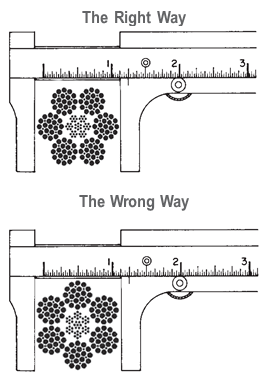
Rope diameter is specified by the user and is generally given in the equipment manufacturer’s instruction manual accompanying the machine on which the rope is to be used.
Rope diameters are determined by measuring the circle that just touches the extreme outer limits of the strands— that is, the greatest dimension that can be measured with a pair of parallel-jawed calipers or machinist’s caliper square. A mistake could be made by measuring the smaller dimension.
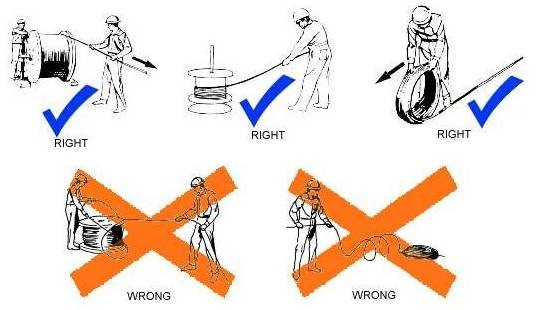
The right way to unreel.To unreel wire rope from a heavy reel, place a shaft through the center and jack up the reel far enough to clear the floor and revolve easily. One person holds the end of the rope and walks a straight line away from the reel, taking the wire rope off the top of the reel. A second person regulates the speed of the turning reel by holding a wood block against the flange as a brake, taking care to keep slack from developing on the reel, as this can easily cause a kink in the rope. Lightweight reels can be properly unreeled using a vertical shaft; the same care should be taken to keep the rope taut.
The wrong way to unreel.If a reel of wire rope is laid on its flange with its axis vertical to the floor and the rope unreeled by throwing off the turns, spirals will occur and kinks are likely to form in the rope. Wire rope always should be handled in a way that neither twists nor unlays it. If handled in a careless manner, reverse bends and kinks can easily occur.
The right way to uncoil.There is only one correct way to uncoil wire rope. One person must hold the end of the rope while a second person rolls the coil along the floor, backing away. The rope is allowed to uncoil naturally with the lay, without spiraling or twisting. Always uncoil wire rope as shown.
The wrong way to uncoil.If a coil of wire rope is laid flat on the floor and uncoiled by pulling it straight off, spirals will occur and kinking is likely. Torsions are put into the rope by every loop that is pulled off, and the rope becomes twisted and unmanageable. Also, wire rope cannot be uncoiled like hemp rope. Pulling one end through the middle of the coil will only result in kinking.
Great stress has been placed on the care that should be taken to avoid kinks in wire rope. Kinks are places where the rope has been unintentionally bent to a permanent set. This happens where loops are pulled through by tension on the rope until the diameter of the loop is only a few inches. They also are caused by bending a rope around a sheave having too severe a radius. Wires in the strands at the kink are permanently damagedand will not give normal service, even after apparent “re-straightening.”
When wire rope is wound onto a sheave or drum, it should bend in the manner in which it was originally wound. This will avoid causing a reverse bend in the rope. Always wind wire rope from the top of the one reel onto the top of the other.Also acceptable, but less so, is re-reeling from the bottom of one reel to the bottom of another. Re-reeling also may be done with reels having their shafts vertical, but extreme care must be taken to ensure that the rope always remains taut. It should never be allowed to drop below the lower flange of the reel. A reel resting on the floor with its axis horizontal may also be rolled along the floor to unreel the rope.
Wire rope should be attached at the correct location on a flat or smooth-faced drum, so that the rope will spool evenly, with the turns lying snugly against each other in even layers. If wire rope is wound on a smooth-face drum in the wrong direction, the turns in the first layer of rope will tend to spread apart on the drum. This results in the second layer of rope wedging between the open coils, crushing and flattening the rope as successive layers are spooled.
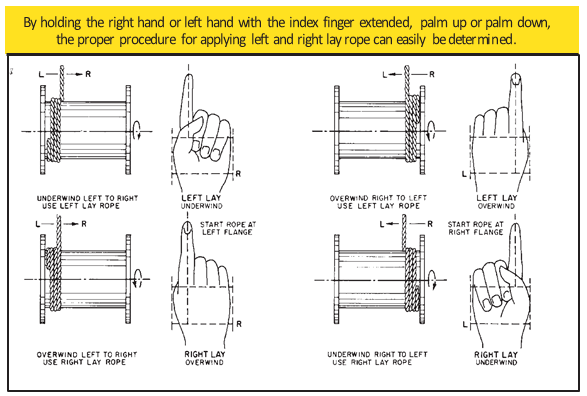
A simple method of determining how a wire rope should be started on a drum. The observer stands behind the drum, with the rope coming towards him. Using the right hand for right-lay wire rope, and the left hand for left lay wire rope, the clenched fist denotes the drum, the extended index finger the oncoming rope.
Clips are usually spaced about six wire rope diameters apart to give adequate holding power. They should be tightened before the rope is placed under tension. After the load is placed on the rope, tighten the clips again to take care of any lessening in rope diameter caused by tension of the load. A wire rope thimble should be used in the eye of the loop to prevent kinking.
U-bolt Clips.There is only one correct method for attaching U-bolt clips to wire rope ends, as shown in TheRightWayimage below. The base of the clip bears on the live end of the rope; the “U” of the bolt bears on the dead end.
Compare this with the incorrect methods. Five of the six clips shown are incorrectly attached—only the center clip in the top view is correct. When the “U” of the clip bears on the live end of the rope, there is a possibility of the rope being cut or kinked, with subsequent failure.
Proper seizing and cutting operations are not difficult to perform, and they ensure that the wire rope will meet the user’s performance expectations. Proper seizings must be applied on both sides of the place where the cut is to be made. In a wire rope, carelessly or inadequately seized ends may become distorted and flattened, and the strands may loosen. Subsequently, when the rope is operated, there may be an uneven distribution of loads to the strands; a condition that will significantly shorten the life of the rope.
Either of the following seizing methods is acceptable. Method No. 1 is usually used on wire ropes over one inch in diameter. Method No. 2 applies to ropes one inch and under.
Method No. 1: Place one end of the seizing wire in the valley between two strands. Then turn its long end at right angles to the rope and closely and tightly wind the wire back over itself and the rope until the proper length of seizing has been applied. Twist the two ends of the wire together, and by alternately pulling and twisting, draw the seizing tight.
The Seizing Wire. The seizing wire should be soft or annealed wire or strand. Seizing wire diameter and the length of the seize will depend on the diameter of the wire rope. The length of the seizing should never be less than the diameter of the rope being seized.
Proper end seizing while cutting and installing, particularly on rotation-resistant ropes, is critical. Failure to adhere to simple precautionary measures may cause core slippage and loose strands, resulting in serious rope damage. Refer to the table below ("Suggested Seizing Wire Diameters") for established guidelines. If core protrusion occurs beyond the outer strands, or core retraction within the outer strands, cut the rope flush to allow for proper seizing of both the core and outer strands.
The majority of wire rope problems occurring during operation actually begin during installation, when the rope is at its greatest risk of being damaged. Proper installation procedures are vital in the protection and performance of wire rope products.
Until the rope is installed it should be stored on a rack, pallet or reel stand in a dry, well-ventilated storage shed or building. Tightly sealed and unheated structures should be avoided as condensation between rope strands may occur and cause corrosion problems. If site conditions demand outside storage, cover the rope with waterproof material and place the reel or coil on a support platform to keep it from coming directly in contact with the ground.
While lubrication is applied during the manufacturing process, the wire rope must still be protected by additional lubrication once it is installed. Lubricants will dry out over a period of time and corrosion from the elements will occur unless measures are taken to prevent this from happening. When the machine becomes idle for a period of time, apply a protective coating of lubricant to the wire rope. Moisture (dew, rain, and snow) trapped between strands and wires will create corrosion if the rope is unprotected. Also apply lubricant to each layer of wire rope on a drum because moisture trapped between layers will increase the likelihood of corrosion.
Always use the nominal diameter as specified by the equipment manufacturer. Using a smaller diameter rope will cause increased stresses on the rope and the probability of a critical failure is increased if the rated breaking strength does not match that of the specified diameter. Using a larger diameter rope leads to shorter service life as the rope is pinched in the sheave and drum grooves which were originally designed for a smaller diameter rope. Just as using a different diameter rope can create performance problems, so can the use of an excessively undersized or oversized rope.
Measure the wire rope using a parallel-jawed caliper as discussed in Measuring Rope Diameter at the top of this page. If the rope is the wrong size or outside the recommended tolerance, return the rope to the wire rope supplier. It is never recommended nor permitted by federal standards to operate cranes with the incorrect rope diameter. Doing so will affect the safety factor or reduce service life and damage the sheaves and drum. Note that in a grooved drum application, the pitch of the groove may be designed for the rope’s nominal diameter and not the actual diameter as permitted by federal standards.
Wire rope can be permanently damaged by improper unreeling or uncoiling practices. The majority of wire rope performance problems start here.Improper unreeling practices lead to premature rope replacement, hoisting problems and rope failure.
Place the payout reel as far away from the boom tip as is practical, moving away from the crane chassis. Never place the payout reel closer to the crane chassis than the boom point sheave. Doing so may introduce a reverse bend into the rope and cause spooling problems. Follow the guidelines highlighted under Unreeling and Uncoiling and Drum Winding. Take care to determine whether the wire rope will wind over or under the drum before proceeding. If the wire rope supplier secured the end of the rope to the reel by driving a nail through the strands, ask that in the future a U-bolt or other nondestructive tie-down method be used; nails used in this manner damage the rope.
Take extra precaution when installing lang lay, rotation-resistant, flattened strand or compacted ropes. Loss of twist must be avoided to prevent the strands from becoming loosened, causing looped wire problems.
The end of the rope must be securely and evenly attached to the drum anchorage point by the method recommended by the equipment manufacturer. Depending on the crane’s regulatory requirements, at least two to three wraps must remain on the drum as dead wraps when the rope is unwound during normal operations. Locate the dead end rope anchorage point on the drum in relation to the direction of the lay of the rope. Do not use an anchorage point that does not correspond with the rope lay. Mismatching rope lay and anchorage point will cause the wraps to spread apart from each other and allow the rope to cross over on the drum. Very gappy winding will occur resulting in crushing damage in multilayer applications.
Back tension must be continually applied to the payout reel and the crewman installing the rope must proceed at a slow and steady pace whether the drum is smooth or grooved.Regardless of the benefits of a grooved drum, tension must be applied to ensure proper spooling. An improperly installed rope on a grooved drum will wear just as quickly as an improperly installed rope on a smooth drum. If a wire rope is poorly wound and as a result jumps the grooves, it will be crushed and cut under operating load conditions where it crosses the grooves.
Every wrap on the first or foundation layer must be installed very tightly and be without gaps. Careless winding results in poor spooling and will eventually lead to short service life. The following layers of rope must lay in the grooves formed between adjacent turns of the preceding layer of rope. If any type of overwind or cross-winding occurs at this stage of installation and is not corrected immediately, poor spooling and crushing damage will occur.
On a multilayer spooling drum be sure that the last layer remains at least two rope diameters below the drum flange top. Do not use a longer length than is required because the excess wire rope will cause unnecessary crushing and may jump the flange. Loose wraps that occur at any time must be corrected immediately to prevent catastrophic rope failure.
The use of a mallet is acceptable to ensure tight wraps, however a steel-faced mallet should be covered with plastic or rubber to prevent damage to the rope wires and strands.
Rotation-resistant ropes of all constructions require extra care in handling to prevent rope damage during installation. The lay length of a rotation-resistant rope must not be disturbed during the various stages of installation. By introducing twist or torque into the rope, core slippage may occur—the outer strands become shorter in length, the core slips and protrudes from the rope. In this condition the outer strands become over- loaded because the core is no longer taking its designed share of the load. Conversely, when torque is removed from a rotation-resistant rope core slippage can also occur. The outer strands become longer and the inner layers or core become overloaded, reducing service life and causing rope failure.
The plain end of a wire rope must be properly secured. If the entire cross section of the rope is not firmly secured, core slippage may occur, causing the core to pull inside the rope’s end and allowing it to protrude elsewhere, either through the outer strands (popped core) or out the other end of the line. The outer layer of the outside strands may also become overloaded as there is no complete core-to-strand support.
Secure the ends of the rope with either seizing or welding methods as recommended under Seizing Wire Rope. It is imperative that the ends be held together tightly and uniformly throughout the entire installation procedure, including attaching the end through the wedge socket and the drum dead end wedge
When installing a new line, connect the old line to the new line by using a swivel-equipped cable snake or Chinese finger securely attached to the rope ends. The connection between the ropes during change-out must be very strong and prevent torque from the old rope being transferred into the new rope.Welding ropes together or using a cable snake without the benefit of a swivel increases the likelihood of introducing torque into the new rope. A swivel-equipped cable snake is not as easy as welding the ropes, but this procedure can be mastered with a little patience and practice.
Your crane"s wire rope works hard. (Almost as hard as you do.) It can deteriorate more quickly than you might think, posing a real danger for you and your crew. In this article, we"ll answer the following questions.
Before we get into that, let"s take a brief moment to go over the proper wire terminology. Understanding the make-up of the wire rope allows you to have a clear understanding of when the rope needs to be replaced.
Flexible steel wire rope is made up of individual wires that make up a strand; these strands are then wrapped around a central core to make up a rope.
Understanding the difference between a wire and a strand is critical. If a strand (grouping of wires) in the rope breaks, the crane wire would need to be replaced. However, if a single wire in the strand breaks, the rope itself may still be usable.
Rag & Visual Inspections: In this method, you use a rag in your inspection, pulling it slowly across the strand, stopping for a closer and more detailed inspection wherever the rag gets caught on a wire.
The Diameter Measurement Method: This method involves comparing the diameter of your rope at various intervals with the rope"s official diameter per the manufacturer"s guidelines. A variation in the rope"s diameter can alert you to potential interior damage that a visual inspection would miss.
Localized Flaw Inspections (LF) vs. Loss of Metallic Area Inspections (LMA) - Both methods use electromagnetics to search for a wire rope"s internal damage.
According to OSHA"s safety regulations, you"re required to inspect your crane"s wire ropes at least every 12 months by qualified professionals. However, OSHA and other experts also recommend inspecting your wire ropes more frequently, such as after every initial installation or repair, or daily before each shift to ensure a safe work environment.
As discussed at the very beginning of this article, we can break down wire rope into three parts. First, wires, which make up strands, and then the strands wrapped around the central core make the rope. Of your total number of wires, you never want more than 10% to be damaged before you need to look into crane wire rope replacement.
According to OSHA, only "trained personnel should carry out inspections," and according to the Crane Manufacturers Association of America, a certified crane inspector should get 2,000+ hours of field experience and training.
We at Americrane & Hoist Corporation are just the experts you need, qualified to offer OSHA inspections and provide operator safety training classes to your employees. Contact us today!

Radically redesigned with never-before-seen features – both inside and out – the S-series will set the standard in lifting for years to come. The newly designed structure includes next-generation features such as off-set reeving, stepless hoisting movement and synthetic rope. The tilted rope drum enables more direct rope angles to decrease the wear and tear of reeving components. And offset reeving means more balanced wheel loads for less stress on the crane structure.
The evolutionary synthetic rope is durable but light and doesn’t require lubrication. The rope also features a strong, symmetric structure for less rope defects and safer handling. Rope angle measurement allows for the use of Smart Features including Hook Centering, Snag Prevention and Follow Me.
Wire ropes are mechanical devices that consist of moving parts working in sync to support a heavy load and move it to its desired direction. The rigging and lifting industry benefits largely from the utilities of the wire rope. Especially when they are used in overhead lifting equipment such as cranes and hoists. The wire rope is attached firmly to a hoist or crane, and the load is fitted using swivels, hooks, or shackles, facilitating controlled movement. It is used in many applications to support suspension towers or bridges and lower or lift elevators.
Wire ropes have become the preferred lifting device in many industrial applications. It has its fair share of reasons as well. Firstly, the unique design allows flexibility, strength, and the ability to handle bending stresses. Depending on the rope"s material, wire, and strand structure, it will provide different sets of benefits for the specific application it is used in.
Selecting the right wire rope for the right application is a process that involves careful thought. Thoughts involving proper analysis of the above aspects of the wire rope and the particular lifting application is required.
The following factors might prove to be impactful in damaging or breaking a wire rope. Wear and tear on areas that are directly in contact with drums and hoist sheaves.
Lack of proper lubrication and heat exposure leading to corrosion. At temp beyond 120 degrees Celsius, a fibre core wire rope will give way and break.
Improper installations are also a common issue that can cause the wire rope to break. Improper installation kinks create a weak section in the rope, which is exploited with prolonged use.

Single girder overhead travelling crane on the rope guide, also known as rope row device, is a relatively simple damage to the attachment. However, many customers do not know how to replace the rope guide. This article briefly introduced the replacement guide rope device approach and process, for your reference.
Single girder overhead travelling crane replacement guide rope device is necessary with matching. Some manufacturers produce can not use the traditional rope guide. Please pay attention to communicate with us when you buy. When replacing the rope guide, should first cut off the power, remove the wire rope. After removing the hexagonal screw of the rope guide, you can take down the rope guide along the wire rope. During this period, it is necessary to pay attention to the wire rope into the rope groove before installing the rope guide, so that the wire rope does not enter the groove, there may again crush the rope guide.
First remove the fixed screws fixed in the rope guide; open the rope guide, the block in the rope guide on the side facing outward, the rope guide into the; wire rope head into the rope guide, adjust the rope guide, straighten out the winding order of the wire rope; wire rope head into the fixed pile, wedge it with iron wedge; fixed rope guide, install all the fixed screws of the rope guide; start, adjust the rope guide. This is to ensure that the upper and lower rope guide can accurately cut off the fire source, do not let the wire rope relax the good position; single girder overhead crane guide rope device device is simple, the device is strong.

In this Crane Rope Products brochure, you’ll find valuable product information and specifications to help you choose the right rope for your application.
Twisted hoist lines can bring a construction project to a sudden halt, resulting in downtime. But the good news is that you can minimize block rotation through proper installation, handling and corrective measures. In this reference document, you will better understand torque and gain tips on how to reduce block rotation.
No single rope can do it all. In this reference document, you will learn how the characteristics of specific ropes should greatly influence your rope choice including: strength, fatigue resistance, crushing resistance, resistance to metal loss and deformation, and resistance to rotation.
In this Product Bulletin, you will learn about the various causes of crushing, the effects of crushing and how to properly evaluate the crushing. Additionally, observations about drum crushing from WireCo WorldGroup engineers are included.
In this product bulletin, you will learn why Category 1 Ropes are special wire ropes that must be handled differently than other wire ropes. Understand why WireCo WorldGroup recommends not removing the welded ends. And, learn the proper step-by-step recommended procedure for cutting and preparing Category 1 Ropes.
In this product bulletin, you will learn WireCo WorldGroup’s preferred technique for installing a hoist rope onto a crane. Learn tips on relieving twist during installation.
In this reference document, you will learn WireCo WorldGroup’s preferred technique for installing rope onto a crane. Additionally, you will learn tips on breaking in your new wire rope, relieving twist, rigging in tight quarters, and cleaning and lubricating ropes.
Despite their durability and strength, wire ropes used on cranes will wear out and need to be retired from service. This reference document will better explain why regular inspection is so crucial to your long-term success.
Learn how to properly install wire rope on mobile cranes. Two factors are key to proper installation no matter what type of equipment, or which wire rope is being used: making sure the rope is free of twist and assuring that the rope is tightly spooled on the drum.
When a load is placed on a rope, torques are created within the rope as wires and strands try to straighten out. Ropes are designed to operate with these load-created torques within them. In this product bulletin, learn four methods of making a lift that is within the capacity of a single-part line. And finally, you will understand the removal criteria of rotation resistant rope.
Using an active, in-line, anti-friction swivel with the majority of types and classes of wire ropes is detrimental to their service life and can lead to unpredictable conditions during operation. This product bulletin provides the basic reasoning behind why swivels aren"t recommended for use with wire ropes except for those that exhibit a similar torque characteristic to that of a category 1 rotation-resistant rope.
XLT4 is designed to be used with a design factor as low as 3.5 on mobile cranes. In this product bulletin, you will learn more about the ASME B30.5 design factor requirements.
XLT4 was designed and engineered to be compatible with a full complement of end terminations including wire rope clips, wedges and swaged crane buttons. In this product bulletin, learn how Union’s 4-strand crane rope delivers more strength than premium 6-strand, and equal or greater stability under load than Category 1 35x7 style rotation-resistance ropes.
XLT4 is truly the four strand mobile crane hoist rope that is unequaled. After reading this product bulletin, you will understand why. You will learn how XLT4 was designed specifically to meet the special wire rope requirements of mobile crane operations and how XLT4 offers a unique combination of characteristics.
More area equals less wear. In this product bulletin, learn why this is important for our XLT4 rope product. After reading this product bulletin, you will understand why XLT4 Crane Rope provides a greater rope footprint when in contact with drums and sheaves and what this means for your application performance. Additionally, you will learn why XLT4 offers less scrubbing and abrasion and why this reduces contact pressure on ropes.

The coil of rope should be placed on the ground and rolled out straight, ensuring that it does not become contaminated with dust, grit, moisture or other harmful material.
The rope should never be pulled away from a stationary coil as this will induce turn into the rope and form kinks. If the coil is too large to physically handle it may need to be placed on a turntable which will allow the rope to be paid out as the end of the rope is pulled away from the coil.
Where multi-layer coiling is involved the rope should be placed in equipment that has the capability of providing a back tension in the rope as it is being transferred from the supply reel to the drum. This is to ensure that the underlying laps of rope, particularly in the bottom layer, are wound tightly on the drum.
The supply reel should be positioned such that the fleet angle during installation is kept to a minimum. If a loop forms in the rope it should not be allowed to tighten to form a kink.
The reel stand should be mounted so as not to create a reverse bend during reeving, i.e. for a drum with an upper wind rope, take the rope off the top of the supply reel
Otherwise, winding can be performed by hanging the wire drum up in a crane hook, the hook must be lowered max., A sufficient weight (2.5% -5% of the wire MBL) must be hooked, and the steel wire could be wound close to the drum
A competent person must begin a visual inspection prior to each shift the equipment is used, which must be completed before or during that shift. The inspection must consist of observation of wire ropes (running and standing) that are likely to be in use during the shift for apparent deficiencies, including those listed in paragraph (a)(2) of this section. Untwisting (opening) of wire rope or booming down is not required as part of this inspection.
Significant distortion of the wire rope structure such as kinking, crushing, unstranding, birdcaging, signs of core failure or steel core protrusion between the outer strands.
In running wire ropes: Six randomly distributed broken wires in one rope lay or three broken wires in one strand in one rope lay, where a rope lay is the length along the rope in which one strand makes a complete revolution around the rope.
In rotation resistant ropes: Two randomly distributed broken wires in six rope diameters or four randomly distributed broken wires in 30 rope diameters.
In pendants or standing wire ropes: More than two broken wires in one rope lay located in rope beyond end connections and/or more than one broken wire in a rope lay located at an end connection.
If a deficiency in Category I (see paragraph (a)(2)(i) of this section) is identified, an immediate determination must be made by the competent person as to whether the deficiency constitutes a safety hazard. If the deficiency is determined to constitute a safety hazard, operations involving use of the wire rope in question must be prohibited until:
If the deficiency is localized, the problem is corrected by severing the wire rope in two; the undamaged portion may continue to be used. Joining lengths of wire rope by splicing is prohibited. If a rope is shortened under this paragraph, the employer must ensure that the drum will still have two wraps of wire when the load and/or boom is in its lowest position.
If a deficiency in Category II (see paragraph (a)(2)(ii) of this section) is identified, operations involving use of the wire rope in question must be prohibited until:
The employer complies with the wire rope manufacturer"s established criterion for removal from service or a different criterion that the wire rope manufacturer has approved in writing for that specific wire rope (see § 1926.1417),
If the deficiency is localized, the problem is corrected by severing the wire rope in two; the undamaged portion may continue to be used. Joining lengths of wire rope by splicing is prohibited. If a rope is shortened under this paragraph, the employer must ensure that the drum will still have two wraps of wire when the load and/or boom is in its lowest position.
If the deficiency (other than power line contact) is localized, the problem is corrected by severing the wire rope in two; the undamaged portion may continue to be used. Joining lengths of wire rope by splicing is prohibited. Repair of wire rope that contacted an energized power line is also prohibited. If a rope is shortened under this paragraph, the employer must ensure that the drum will still have two wraps of wire when the load and/or boom is in its lowest position.
Where a wire rope is required to be removed from service under this section, either the equipment (as a whole) or the hoist with that wire rope must be tagged-out, in accordance with § 1926.1417(f)(1), until the wire rope is repaired or replaced.
Wire ropes on equipment must not be used until an inspection under this paragraph demonstrates that no corrective action under paragraph (a)(4) of this section is required.
At least every 12 months, wire ropes in use on equipment must be inspected by a qualified person in accordance with paragraph (a) of this section (shift inspection).
The inspection must be complete and thorough, covering the surface of the entire length of the wire ropes, with particular attention given to all of the following:
Exception: In the event an inspection under paragraph (c)(2) of this section is not feasible due to existing set-up and configuration of the equipment (such as where an assist crane is needed) or due to site conditions (such as a dense urban setting), such inspections must be conducted as soon as it becomes feasible, but no longer than an additional 6 months for running ropes and, for standing ropes, at the time of disassembly.
If the deficiency is localized, the problem is corrected by severing the wire rope in two; the undamaged portion may continue to be used. Joining lengths of wire rope by splicing is prohibited. If a rope is shortened under this paragraph, the employer must ensure that the drum will still have two wraps of wire when the load and/or boom is in its lowest position.
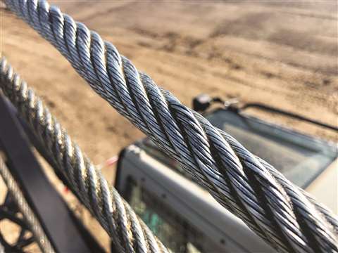
Wire rope forms an important part of many machines and structures. It is comprised of continuous wire strands wound around a central core. There are many kinds of wire rope designed for different applications. Most of them are steel wires made into strands wound with each other. The core can be made of steel, rope or even plastics.
Wire ropes (cables) are identified by several parameters including size, grade of steel used, whether or not it is preformed, by its lay, the number of strands and the number of wires in each strand.
A typical strand and wire designation is 6x19. This denotes a rope made up of six strands with 19 wires in each strand. Different strand sizes and arrangements allow for varying degrees of rope flexibility and resistance to crushing and abrasion. Small wires are better suited to being bent sharply over small sheaves (pulleys). Large outer wires are preferred when the cable will be rubbed or dragged through abrasives.
There are three types of cores. An independent wire rope core (IWRC) is normally a 6x7 wire rope with a 1x7 wire strand core resulting in a 7x7 wire rope. IWRCs have a higher tensile and bending breaking strength than a fiber core rope and a high resistance to crushing and deformation.
A wire strand core (WSC) rope has a single wire strand as its core instead of a multistrand wire rope core. WSC ropes are high strength and are mostly used as static or standing ropes.
Wire ropes also have fiber cores. Fiber core ropes were traditionally made with sisal rope, but may also use plastic materials. The fiber core ropes have less strength than steel core ropes. Fiber core ropes are quite flexible and are used in many overhead crane applications.
The lay of a wire rope is the direction that the wire strands and the strands in the cable twist. There are four common lays: right lay, left lay, regular lay and lang lay. In a right lay rope the strands twist to the right as it winds away from the observer. A left lay twists to the left. A regular lay rope has the wires in the strands twisted in the opposite direction from the strands of the cable. In a lang lay rope, the twist of the strands and the wires in the strands are both twisted the same way. Lang lay ropes are said to have better fatigue resistance due to the flatter exposure of the wires.
Wire ropes are made mostly from high carbon steel for strength, versatility, resilience and availability and for cost consideration. Wire ropes can be uncoated or galvanized. Several grades of steel are used and are described in Table 1.
Steel cable wire is stiff and springy. In nonpreformed rope construction, broken or cut wires will straighten and stick out of the rope as a burr, posing a safety hazard. A preformed cable is made of wires that are shaped so that they lie naturally in their position in the strand, preventing the wires from protruding and potentially causing injury. Preformed wire ropes also have better fatigue resistance than nonpreformed ropes and are ideal for working over small sheaves and around sharp angles.
Lubricating wire ropes is a difficult proposition, regardless of the construction and composition. Ropes with fiber cores are somewhat easier to lubricate than those made exclusively from steel materials. For this reason, it is important to carefully consider the issue of field relubrication when selecting rope for an application.
There are two types of wire rope lubricants, penetrating and coating. Penetrating lubricants contain a petroleum solvent that carries the lubricant into the core of the wire rope then evaporates, leaving behind a heavy lubricating film to protect and lubricate each strand (Figure 2). Coating lubricants penetrate slightly, sealing the outside of the cable from moisture and reducing wear and fretting corrosion from contact with external bodies.
Both types of wire rope lubricants are used. But because most wire ropes fail from the inside, it is important to make sure that the center core receives sufficient lubricant. A combination approach in which a penetrating lubricant is used to saturate the core, followed with a coating to seal and protect the outer surface, is recommended. Wire rope lubricants can be petrolatum, asphaltic, grease, petroleum oils or vegetable oil-based (Figure 3).
Petrolatum compounds, with the proper additives, provide excellent corrosion and water resistance. In addition, petrolatum compounds are translucent, allowing the technician to perform visible inspection. Petrolatum lubricants can drip off at higher temperatures but maintain their consistency well under cold temperature conditions.
Various types of greases are used for wire rope lubrication. These are the coating types that penetrate partially but usually do not saturate the rope core. Common grease thickeners include sodium, lithium, lithium complex and aluminum complex soaps. Greases used for this application generally have a soft semifluid consistency. They coat and achieve partial penetration if applied with pressure lubricators.
Petroleum and vegetable oils penetrate best and are the easiest to apply because proper additive design of these penetrating types gives them excellent wear and corrosion resistance. The fluid property of oil type lubricants helps to wash the rope to remove abrasive external contaminants.
Wire ropes are lubricated during the manufacturing process. If the rope has a fiber core center, the fiber will be lubricated with a mineral oil or petrolatum type lubricant. The core will absorb the lubricant and function as a reservoir for prolonged lubrication while in service.
If the rope has a steel core, the lubricant (both oil and grease type) is pumped in a stream just ahead of the die that twists the wires into a strand. This allows complete coverage of all wires.
After the cable is put into service, relubrication is required due to loss of the original lubricant from loading, bending and stretching of the cable. The fiber core cables dry out over time due to heat from evaporation, and often absorb moisture. Field relubrication is necessary to minimize corrosion, protect and preserve the rope core and wires, and thus extend the service life of the wire rope.
If a cable is dirty or has accumulated layers of hardened lubricant or other contaminants, it must be cleaned with a wire brush and petroleum solvent, compressed air or steam cleaner before relubrication. The wire rope must then be dried and lubricated immediately to prevent rusting. Field lubricants can be applied by spray, brush, dip, drip or pressure boot. Lubricants are best applied at a drum or sheave where the rope strands have a tendency to separate slightly due to bending to facilitate maximum penetration to the core. If a pressure boot application is used, the lubricant is applied to the rope under slight tension in a straight condition. Excessive lubricant application should be avoided to prevent safety hazards.
Some key performance attributes to look for in a wire rope lubricant are wear resistance and corrosion prevention. Some useful performance benchmarks include high four-ball EP test values, such as a weld point (ASTM D2783) of above 350 kg and a load wear index of above 50. For corrosion protection, look for wire rope lubricants with salt spray (ASTM B117) resistance values above 60 hours and humidity cabinet (ASTM D1748) values of more than 60 days. Most manufacturers provide this type of data on product data sheets.
Cable life cycle and performance are influenced by several factors, including type of operation, care and environment. Cables can be damaged by worn sheaves, improper winding and splicing practices, and improper storage. High stress loading, shock loading, jerking heavy loads or rapid acceleration or deceleration (speed of the cable stopping and starting) will accelerate the wear rate.
Corrosion can cause shortened rope life due to metal loss, pitting and stress risers from pitting. If a machine is to be shut down for an extended period, the cables should be removed, cleaned, lubricated and properly stored. In service, corrosion and oxidation are caused by fumes, acids, salt brines, sulfur, gases, salt air, humidity and are accelerated by elevated temperatures. Proper and adequate lubricant application in the field can reduce corrosive attack of the cable.
Abrasive wear occurs on the inside and outside of wire ropes. Individual strands inside the rope move and rub against one another during normal operation, creating internal two-body abrasive wear. The outside of the cable accumulates dirt and contaminants from sheaves and drums. This causes three-body abrasive wear, which erodes the outer wires and strands. Abrasive wear usually reduces rope diameter and can result in core failure and internal wire breakage. Penetrating wire rope lubricants reduce abrasive wear inside the rope and also wash off the external surfaces to remove contaminants and dirt.
Many types of machines and structures use wire ropes, including draglines, cranes, elevators, shovels, drilling rigs, suspension bridges and cable-stayed towers. Each application has specific needs for the type and size of wire rope required. All wire ropes, regardless of the application, will perform at a higher level, last longer and provide greater user benefits when properly maintained.
Lubrication Engineers, Inc. has found through years of field experience, that longer wire rope life can be obtained through the use of penetrating lubricants, either alone or when used in conjunction with a coating lubricant. Practical experience at a South African mine suggests that life cycles may be doubled with this approach. At one mine site, the replacement rate for four 44-mm ropes was extended from an average 18.5 months to 43 months. At another mine, life cycles of four 43-mm x 2073 meter ropes were extended from an average 8 months to 12 months.
In another study involving 5-ton and 10-ton overhead cranes in the United States that used 3/8-inch and 5/8-inch diameter ropes, the average life of the ropes was doubled. The authors attribute this increased performance to the ability of the penetrating lubricant to displace water and contaminants while replacing them with oil, which reduces the wear and corrosion occurring throughout the rope. A good spray with penetrating wire rope lubricant effectively acts as an oil change for wire ropes.
In these examples, the savings in wire rope replacement costs (downtime, labor and capital costs) were substantial and dwarfed the cost of the lubricants. Companies who have realized the importance of proper wire rope lubrication have gained a huge advantage over those who purchase the lowest priced lubricant, or no lubricant at all, while replacing ropes on a much more frequent basis.
吊,搬送する大型天井クレーン等の分野で利用される。Description: TECHNICAL FIELD The present invention relates to a method for replacing a wire rope of a crane, and more particularly, to efficiently use an old wire rope wound around a hoisting drum installed on a crane. The present invention relates to a method of replacing a new wire rope with an old wire rope which can be automatically wound on the ground. This is used in the field of large overhead cranes that suspend and transport heavy objects such as coiled steel plates and ingots.
えたフックブロック8を懸吊している。A wire rope wound around a hoisting drum such as a large overhead crane installed in a rolling mill of a steel mill is, for example,
いう)までも解く。In such an overhead crane, replacement work of the old wire rope 6 has been conventionally performed as follows. As shown in FIG. 9, first, the hoisting drum 5 is rotated in the hoisting direction (the direction opposite to the arrow 42), and the hoisting drum 5 is rotated.
The views of the old wire rope 6 are sequentially solved from the winding grooves 5c and 5d in the left-right inverted spiral shape engraved on the hook block 8, and the hook block 8 is lowered onto the support base 9 placed on the ground and firmly mounted.
Remove one end 6a (see FIG. 10) of the old wire rope 6 that is hung on the floor, tie the end 6a with a cremona rope (not shown), and lower it to the ground. Then, the Cremona rope is removed, and one end of the new wire rope 10 wound around the feeding means 11 arranged in advance on the ground and one end 6a of the old wire rope 6 are connected by a connecting fitting (not shown) or the like. . After that, the hoisting drum 5 is rotated in the hoisting direction 42, and the new wire rope 10 is started to be pulled up to the hoisting drum 5, while the old wire rope 6 is wound about three times around the winding groove 5d of the hoisting drum 5. Let This is to secure a frictional force such that the old wire rope 6 and the new wire rope 10 do not slip on the hoisting drum 5 when the hoisting drum 5 is subsequently rotated in the hoisting direction 42 and the old wire rope 6 is paid out. This is to keep it. After that, the other end 6b (the first end) of the old wire rope 6 hooked on the fixture 5b provided on the other end of the hoisting drum 5 (first
戻し、再度、上記と同じ作業を繰り返す。The other end of the old wire rope 6 is tied with a cremona rope or the like, and in this state, the hoisting drum 5 is further rotated in the hoisting direction 42, while the other end is guided so as not to bounce, while the club 4 is being guided. The old wire rope 6 is let out to the ground through the handrail 4a, and the worker waiting on the ground bundles the old wire rope 6 in a ring shape. During this operation, the old wire rope 6 wound around the winding drum 5 moves in the direction of the arrow 44 along the spiral winding groove 5d. When the wound portion of the old wire rope 6 reaches the central position approaching the winding groove 5c of the reverse spiral, there is no winding allowance for the old wire rope 6 to move, and at that time, the rotation of the hoisting drum 5 To stop. The old wire rope 6 in the wound state is loosened on the hoisting drum 5 by the operator"s manual work so as to float from the winding groove 5d, and the old wire rope 6 is left as it is at the left end of the winding groove 5d where the fixture 5b is located. Return to and repeat the same operation as above.
了される。When the connection between the new wire rope 10 and the old wire rope 6 reaches the upper position 43 of the hoist drum 5 by sequentially tracing the hook block 8 and the upper sheave 7 (see FIG. 10) by such work. The rotation of the hoisting drum 5 is stopped, the connecting portion is disconnected, and one end of the new wire rope 10 is hooked on the fixture 5b of the hoisting drum 5. The other end 6b of the old wire rope 6
Is tied with a cremona rope, and it is lowered to the ground, and the last part of the old wire rope 6 is also bundled into a ring on the ground. On the other hand, the other end of the new wire rope 10 is removed from the feeding means 11, the other end is tied with a cremona rope or the like and pulled up onto the club 4, and the other end is hooked on the fixture 5a of the hoisting drum 5. After the hoisting drum 5 is rotated in the hoisting direction 42 and the new wire rope 10 is additionally wound at both ends of the hoisting drum 5, the hoisting drum 5 is further rotated in the hoisting direction, whereby the new wire rope 10 Is wound around the hoisting drum 5, and the hook block 8 rises. In this way, the replacement work of the old wire rope 6 and the new wire rope 10 is completed.
非常に煩わしいものであった。In such a conventional replacement method, while rotating the hoisting drum 5 at the high position of the ceiling part, the old wire rope 6 is unwound to the ground, while the unwound old wire rope 6 is bundled by the operator on the ground. It was being done. For large overhead cranes, the diameter of the wire rope used for them is as large as 25 mm to 40 mm, and the work of bundling them is not very efficient because it requires a lot of manpower and is a very heavy work. In addition, it is necessary for the bundling operator and the crane operator to work while constantly signaling each other.
提案した。For this reason, the applicant of the present invention, after fixing the hook block to the ground, connects one end of the old wire rope to the new wire rope and connects the other end of the old wire rope to the winding means separately prepared. JP-A-63-17792 proposes a method for replacing the wire rope of a crane, in which the old wire rope is wound up only by the pulling force driven by the winding means without driving the hoisting drum. did.
善が強く望まれていた。In the above method, the pulling force of the winding means arranged on the ground acts on the entire wire rope, and by extension, the old wire rope in the portion stretched between the upper sheave and the hook block is also directly affected. It was necessary to fix the hook block particularly firmly. In addition, the strength of the winding means must be increased in order to obtain a sufficient tensile force, and the drive source requires considerably large power. This is even more so when the wire rope is thick and heavy, which causes problems such as an increase in the size of the device and an increase in cost, and a restriction on the work space. Further, since a large tension acts on the wire rope, the connection portion between the new wire rope and the old wire rope may be disconnected, and improvement of the work has been strongly desired.
ープ取替方法を提供することである。The present invention has been made in consideration of such circumstances, and an object of the present invention is not to require a compact and large space, to keep a large tension applied to the wire rope at all times, and to make the wire rope thick. It is an object of the present invention to provide a method for replacing a wire rope of a crane, in which the safety of the replacement work is highly secured and the wire rope can be efficiently replaced with a new wire rope.
けるワイヤロープの取替方法に適用される。INDUSTRIAL APPLICABILITY The present invention is applied to a method for replacing a wire rope in a crane equipped with a hoisting drum for winding a wire rope, which is installed on a truck traveling on a rail.
It is lowered to the ground by rotating in the winding direction (the direction opposite to the arrow 42), and is unwound from the hoisting drum 5 to the old winding of the old wire rope 6. The one end 6a of the old wire rope 6 is removed from one end of the hoisting drum 5, and the one end 6a of the old wire rope 6 is lowered to the ground and connected to one end of the new wire rope 10 wound around the feeding means 11. Next, the hoisting drum 5 is rotated in the hoisting direction 42, and the old wire rope 6 is wound around the hoisting drum 5 a predetermined number of times. Remove the other end 6b. Rotate the hoisting drum 5 further in the hoisting direction 42,
The new wire rope 10 is started to be pulled up to the hoisting drum 5, and the other end 6b of the old wire rope 6 is fed to the ground. The other end 6b of the old wire rope 6 is connected to the rotary table 17 arranged on the ground, and the winding direction of the winding drum 5 thereafter is increased.
The old wire rope 6 is fed to the ground by rotating the old wire rope 6 and the rotation speed of the rotary table 17 is adjusted so that the old wire rope 6 has a desired winding diameter without tension. That is, the ropes 6 are stacked in a ring shape and bundled.
うにしてもよい。Further, referring to FIG. 5, the iron cage 18 having a cylindrical iron cage 18a surrounded by the old wire ropes 6 which are stacked in a ring shape is detachably provided on the rotary table 17 and is fed to the ground. The old wire rope 6 may be bundled in a ring shape by the rotation of the rotary table 17 while preventing the winding wire of the old wire rope 6 from being disturbed by the cylindrical basket portion 18a.
While contacting the old wire rope 6 that has been fed to the ground through the upper opening of 8c, to the ring-shaped pipe material that is located at the boundary between the truncated cone-shaped groin portion 18b and the truncated cone-shaped small groin portion 18c. Alternatively, the old wire ropes 6 may be stacked and bundled in a ring shape by the rotation of the rotary table 17.
とした巻き取りを実現することができる。According to the present invention, one end of an old wire rope removed from a hoisting drum is connected to a new wire rope, and the old wire rope is wound around the hoisting drum a predetermined number of times, and then the hoisting drum is rotated in a hoisting direction. Since the other end of the old wire rope is drawn to the ground while being made to move, the old wire rope can be reliably drawn without slipping, and the new wire rope can be wound around the hoisting drum. Then, the old wire rope is extended to the other side by the rotation of the hoisting drum in the winding direction and the rotation speed of the rotary table is adjusted to connect the old wire rope to the movement of the rotary table arranged on the ground. Since the wire rope is wound, it is possible to efficiently stack the old wire ropes in a loop so that the old wire ropes have a desired winding diameter without exerting a large tension on the wire ropes. That is, if the rotation speed of the rotary table is increased, the winding can be made thinner, and if the winding is tightened too much, it can be slowed down and corrected, or a large bunch of wheels can be stacked. Orderly winding can be achieved with any diameter.
ないものとしておくことができる。If a carcass with a cylindrical cage that surrounds the old wire ropes that are bundled in a ring shape is detachably attached to the rotating table, the disorder of the winding appearance of the old wire ropes that have been fed to the ground will be cylindrical. Part is prevented by
The old wire rope can be smoothly looped and bundled by rotating the rotary table. For example, if the old wire rope suddenly jumps out, the cylindrical cage prevents it. Further, even if the ring-shaped bundle is greatly tilted, it is prevented from deviating from the turntable. Of course, the old wire ropes can be bundled compactly to facilitate the subsequent treatment, and the winding means can be made to require no space.
しておきたい場合に都合がよい。By forming a truncated cone-shaped basket on the upper part of the cylindrical basket, the old wire rope that is fed to the ground is brought into contact with the inner surface of the truncated cone and the rotary table rotates to form a ring shape. Can be stacked and bundled. For example, even if a situation occurs in which the old wire rope is excessively shaken by centrifugal force or the like due to the rotation of the turntable, the wound form after that is not greatly impaired. This is convenient when it is desired to keep the winding diameter large.
同心状の巻取り姿となるよう誘導することができる。A small frustoconical small squirrel cage is formed in the upper part of the frustoconical squirrel cage, and the old wire rope that is fed to the ground through the upper opening


 8613371530291