
rotation resistant wire rope inspection quotation

A competent person must begin a visual inspection prior to each shift the equipment is used, which must be completed before or during that shift. The inspection must consist of observation of wire ropes (running and standing) that are likely to be in use during the shift for apparent deficiencies, including those listed in paragraph (a)(2) of this section. Untwisting (opening) of wire rope or booming down is not required as part of this inspection.
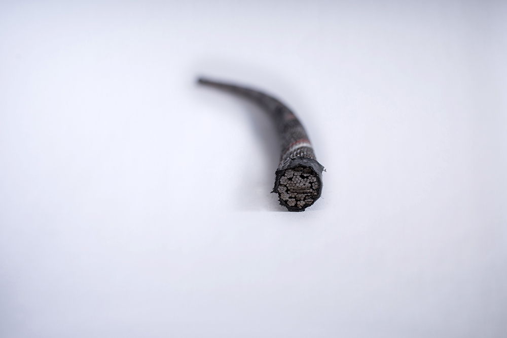
Significant distortion of the wire rope structure such as kinking, crushing, unstranding, birdcaging, signs of core failure or steel core protrusion between the outer strands.
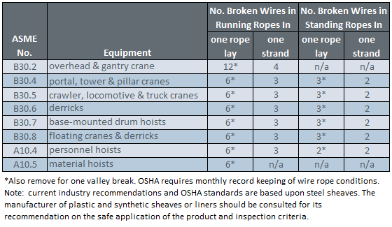
In running wire ropes: Six randomly distributed broken wires in one rope lay or three broken wires in one strand in one rope lay, where a rope lay is the length along the rope in which one strand makes a complete revolution around the rope.
In rotation resistant ropes: Two randomly distributed broken wires in six rope diameters or four randomly distributed broken wires in 30 rope diameters.
In pendants or standing wire ropes: More than two broken wires in one rope lay located in rope beyond end connections and/or more than one broken wire in a rope lay located at an end connection.
If a deficiency in Category I (see paragraph (a)(2)(i) of this section) is identified, an immediate determination must be made by the competent person as to whether the deficiency constitutes a safety hazard. If the deficiency is determined to constitute a safety hazard, operations involving use of the wire rope in question must be prohibited until:
If the deficiency is localized, the problem is corrected by severing the wire rope in two; the undamaged portion may continue to be used. Joining lengths of wire rope by splicing is prohibited. If a rope is shortened under this paragraph, the employer must ensure that the drum will still have two wraps of wire when the load and/or boom is in its lowest position.
If a deficiency in Category II (see paragraph (a)(2)(ii) of this section) is identified, operations involving use of the wire rope in question must be prohibited until:
The employer complies with the wire rope manufacturer"s established criterion for removal from service or a different criterion that the wire rope manufacturer has approved in writing for that specific wire rope (see § 1926.1417),
If the deficiency is localized, the problem is corrected by severing the wire rope in two; the undamaged portion may continue to be used. Joining lengths of wire rope by splicing is prohibited. If a rope is shortened under this paragraph, the employer must ensure that the drum will still have two wraps of wire when the load and/or boom is in its lowest position.
If the deficiency (other than power line contact) is localized, the problem is corrected by severing the wire rope in two; the undamaged portion may continue to be used. Joining lengths of wire rope by splicing is prohibited. Repair of wire rope that contacted an energized power line is also prohibited. If a rope is shortened under this paragraph, the employer must ensure that the drum will still have two wraps of wire when the load and/or boom is in its lowest position.
Where a wire rope is required to be removed from service under this section, either the equipment (as a whole) or the hoist with that wire rope must be tagged-out, in accordance with § 1926.1417(f)(1), until the wire rope is repaired or replaced.
The inspection must include any deficiencies that the qualified person who conducts the annual inspection determines under paragraph (c)(3)(ii) of this section must be monitored.
Wire ropes on equipment must not be used until an inspection under this paragraph demonstrates that no corrective action under paragraph (a)(4) of this section is required.
At least every 12 months, wire ropes in use on equipment must be inspected by a qualified person in accordance with paragraph (a) of this section (shift inspection).
The inspection must be complete and thorough, covering the surface of the entire length of the wire ropes, with particular attention given to all of the following:
Exception: In the event an inspection under paragraph (c)(2) of this section is not feasible due to existing set-up and configuration of the equipment (such as where an assist crane is needed) or due to site conditions (such as a dense urban setting), such inspections must be conducted as soon as it becomes feasible, but no longer than an additional 6 months for running ropes and, for standing ropes, at the time of disassembly.
If the deficiency is localized, the problem is corrected by severing the wire rope in two; the undamaged portion may continue to be used. Joining lengths of wire rope by splicing is prohibited. If a rope is shortened under this paragraph, the employer must ensure that the drum will still have two wraps of wire when the load and/or boom is in its lowest position.
If the qualified person determines that, though not presently a safety hazard, the deficiency needs to be monitored, the employer must ensure that the deficiency is checked in the monthly inspections.
All documents produced under this section must be available, during the applicable document retention period, to all persons who conduct inspections under this section.

All running ropes in service should be visually inspected, at least, once each working day. A visual inspection shall consist of observation of all rope which can reasonably be expected to be in use during the day’s operations.
A – Distortion of the rope such as kinking, crushing, unstranding, birdcaging, main strand displacement, or core protrusion. Loss of rope diameter in a short rope length or unevenness of outer strands should provide evidence that the rope must be replaced.
Inspect the entire length of the rope. Some areas of the wire rope such as around the core are more difficult to inspect. To inspect the core, examine the rope as it passes over the sheaves. The strands have a tendency to open up slightly which will give the inspector a better view of the core. Also regularly inspect for any reduction in diameter and lengthening of rope lay as both conditions indicate core damage.
The load which a new wire rope may handle under given operating conditions and at an assumed design factor. A design factor of five is chosen most frequently for wire rope. (Operating loads not to exceed 20% of catalog breaking strength). Operating loads may have to be reduced when life, limb, or valuable property are at risk, or other than new wire rope is used. A design factor of 10 is usually chosen when wire rope is used to carry personnel. (Operating loads not to exceed 10% of catalog breaking strength). Responsibility for choosing a design factor with the user.
Rope sockets, thimbles, sleeves, hooks, links, shackles, sheaves, blocks, etc., must match in size, materials and strength, to provide adequate safety protection. Proper installation is crucial for maximum efficiency and safety.
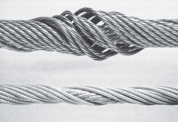
The lay of strands (wire rope) can be twisted either to the left or to the right. To determine whether the lay is left or right handed, look along the rope and see whether the wires appear to turn anti-clockwise (let handed) or clockwise (right handed) as they get further away from you.
Note: Regular rope inspection and maintenance shall be carried out according to the guideline instructions provided by the manufacturer and according to international standard ISO 4309:2009.
Note: The internal examination of wire rope shall not be done as part of regular maintenance, unless the person is trained for that examination (ISO4309 Annex D).

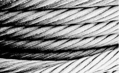
Using the rope to its maximum fatigue life will cause the rope to deteriorate from the inside out. Sudden rope failures may be the result. For this reason we do not recommend this construction for tower cranes. There have been fatal and catastrophic accidents involving this rope construction because of undetected inner rope fatigue.
However, mobile and truck mounted cranes are operated on a much less severe duty cycle and it is not expected that 19x7 has to be replaced because of inner rope fatigue but because of other mechanical damages. Keep in mind that this statement covers normal mobile crane use. If you use a mobile crane like a production crane you WILL experience the above mentioned danger situations.

EN12385-2 Steel wire ropes – Safety – Definitions, designation and classification provides a detailed explanation of all the terms and abbreviations used when describing a wire rope and its components. Below are a few of the most common abbreviations;
Steel wire ropes are specified in terms of a Nominal Rope Diameter and when produced have a manufacturing diameter tolerance, this tolerance can vary depending upon customer requirements and specifications and is often dictated by the diameter of grooving within sheaves and drums in which the wire rope will be expected to operate. If no diameter tolerance is specified, the general diameter tolerance is, Nominal Diameter +0% to +5% as specified within various International Rope Standards (EN12385-4, API-9A, ISO 2408). However, please note other diameter tolerances may be applied to ‘small’ diameter ropes and ropes used for specific applications/industries e.g. Mining, Aerials, Elevators, etc.
When designing any rope operated equipment, designers should consider the relevant National and/or International Standards which refer to acceptable sheave and drum diameters based upon the application, industry, etc. The diameter of sheaves and drums together with the tension, are normally associated with overall service life of the rope and in ‘simple terms’ the larger the diameter the longer the service life, although consideration should also be given to the anticipated modes of rope deterioration which will also significantly affect the service life. Typically, the diameter of sheaves and drums for crane applications are 16 to 28 times the nominal rope diameter.
Wire ropes are generally subjected to a visual examination and specifically for crane ropes these is an International Standard ISO 4309 “Cranes – Wire ropes – Care and maintenance, inspection and discard” which provides guidance on the inspection of wire ropes and provide the discard criteria. The document also includes information on the Magnetic testing of roper in service / Non-Destructive Examination and how this can assist the competent person in combination with his visual examination, determine the overall condition of the rope. All wire ropes should be inspected on a routine basis by a competent person to ensure that they remain is a good condition whilst in service and removed from service before they become dangerous. However, this standard is used for offering guidance for ropes operating in other systems where no specific discard criteria are given for that application, industry or country in which the rope is operating.
Please note, wire ropes can cause death and/or serious injury if not correctly handles, operated and maintained to good condition and care should always be taken when work with or close to wire ropes.
A new rope can easily be damaged if the pulley wheel groove is too tight, this will in effect pinch the rope probably causing a wave (spiral) deformity in your new rope.
If left unchecked in a steel pulley, parallel, linear fatigue wire breaks will be found where the contact pressures have become too high, due to a pinch affect.
The Lang’s construction, due to the wires running across the axis of the rope is the same direction as the strand, provides a greater length of wire on the exterior surface of the rope and hence since there is an increased surface area there is an increased area of steel to wear away before a broken wire occurs, therefore offering greater wear resistance. Therefore, applications where the rope is operating over larger number of support rollers and/or sheaves, the Lang’s lay rope may be of benefit.
The direction of the wires within the Lang’s lay construction also reduces the level of mechanical damage and rope interference, which takes place between adjacent wraps of rope within the crossover zones during multi-layer spooling of wire rope.
It is important to state that, single layer strand and parallel laid, rope constructions, manufactured in Lang’s lay, MUST NOT be used with one end free to rotate. Since the wires and the strands as twisted in the same direction, if the rope is free to rotate the wires and the strands will untwist tighter and seriously affect the integrity and breaking strength of the rope.
Wire ropes may be considered as machines, each with approximately 200 to 300 individual wires, which move independently to each over whenever ropes operate around sheaves or spool on or off winch drums, therefore ensuring ropes are lubricated internally will minimise the level of friction between the individual wires and optimise the ropes bend fatigue performance. Lubricant internally and externally will protect the ropes from corrosion and this applies equally to both un-galvanised/bright ropes and galvanised rope. Although the zinc on the surface of the individual wires of a galvanised rope will protect the wires from corrosion, once the zinc has sacrificed itself (oxidised) to protect the steel, the wires are then susceptible to corrosion. The longer the zinc can be protected by the lubricant the longer the zinc remains to offer protection to the steel. However there are applications where internal or external lubricant on the rope may not be advisable, anywhere the lubricant could drop off the rope and contaminate products (paper, food, etc.) in the vicinity of the rope or where the lubricant on the exterior of the rope may be contaminated with debris in the atmosphere (grit, sand, etc.). In this application, it must be accepted that ‘dry’ ropes will have a significantly reduced service life.
Ropes may be lubricated in-service with either oil or grease, both products offering slightly different benefits. Oils may be applied from a portable spray unit and although the ropes may require being re-lubricated more frequently, since it is relatively easy and cleaning to apply, operators are more likely to re-lubricate the ropes in service. The thin oil may penetrate the rope and surface coat the exterior of the rope with a thin film of lubricant, which also allows for relatively easy routine visual inspection of the rope. Alternatively, rope may be lubricated with a soft bearing type grease; the grease may be applied using a suitable pressure greasing system (Masto, Viper, etc.) to ensure uniform coating of grease along the total length of the rope passing through the greasing system, although the level and colour of grease may make visual inspection difficult. It is important that any oil or grease used to lubricate ropes in service is compatible with the lubricant applied to the rope during manufacturing and Bridon-Bekaert offer a range of wire rope lubricants specially formulated to be suitable for most environments and operations, including ECO VGP 2013 compliant (Bio-degradable, Non-toxic & Non-accumulative) products.
For ropes operating above ambient temperature consideration must be given to the effects the operating temperature may have on the wire rope. For guidance, unless otherwise stated, the maximum operating temperatures are provided in the International Standards e.g. EN 12385-3. However searches of these standards by Bridon-Bekaert indicate that the quoted temperatures within the standards have remained constant for a significant period of time, having been developed when rope constructions and usage centred around common 6-stranded rope constructions. With the introduction of more complex rope constructions incorporating higher tensile grade wires, synthetic lubricants and polymers, Bridon-Bekaert’s experiences indicate that reconsideration of the maximum operating temperatures is required. For high performance ropes incorporating synthetic lubricants and polymers Bridon-Bekaert recommend a maximum operating temperature of 100 degrees C. Excessive bleed out of lubricant from the rope may occur depending upon the rope operating temperature and the type/composition of the lubricant and frequent re-lubrication may be required.
Certain applications (Heave compensation systems, etc.) can generate high operating temperatures and for these and any application or where ropes are stored above ambient temperature, Bridon-Bekaert would be please to discuss this subject further.
Also due the smoothness of the circumference of these rope designs, they reduce wear at the cross over contact points as the rope wraps over itself as it is wound onto the drum.
An Ordinary lay rope is where the individual wires in the outer strands are spun / twisted together in the opposite direction to the direction the outer strands are twisted around the core, which results in the individual wires running along the axis of the rope. A Lang’s lay rope is where the individual wires in the outer stands are twisted in the same direction as the outer strands are twisted around the core, which results in the individual wires running across the rope in the same direction as the strands.
It is important to state that a left hand lay rope and a right hand lay rope MUST never be joined together unless the jointing mechanism is prevented from rotating, otherwise the rope will be allowed to un-twist together, which may have a significant effect on the integrity of the ropes, and could result in failure of the rope. There are two particular situations/arrangements where a left hand and/or right hand rope combination may be considered beneficial;
To prevent rotation of load – Twin rope operating systems (Overhead hoists, Grabbing systems, Container handling cranes, etc.) are generally designed to utilise one left hand rope and one right hand lay rope. When lifting a load both ropes will be subjected to an axial load and will try to un-twist, but since the ropes have been spun in different directions during manufacture one rope will trying to un-twist in one direction whilst the other rope will try to un-twist in the opposite direction, the two ropes therefore acting against each other to prevent/minimise rotation of the load.
When spooling a rope – Tension is generally applied to ropes whilst they are being spooled on to a winch drum and this tension will try to rotate / untwist the rope and therefore it is preferable to have the rope rotating up against the previous wrap of rope to minimise ‘gapping’ between the adjacent wrap of rope particularly on the bottom layer. Therefore, to achieve this, depending if the rope is anchored on the left or right hand side of the drum or the rope is being spooled under-wound or over-wound will determine if, a left or right hand lay rope should be utilised.
Rotation Resistant ropes are normally used to lift or suspend a load without the load rotating (example, hoist ropes used on Offshore, Mobile and Tower cranes, etc.) and are constructed by spinning the inner part of the rope in one direction and the outer part of the rope in the opposite direction. When an axial load is then applied to the rope the inner part will try to untwist in one direction and the outer part will try to untwist in the opposite direction, with the two parts of the rope reacting against each other. Rotation Resistant ropes are normally of a multi-strand construction and constructed of 2-layers of strands with the inner layer spun in the opposite direction to the outer layer and of 3-layers of strands with the inner two layers spun in the opposite direction to the outer layer. Three and four stranded rope constructions may also be considered as rotation resistant, but having only three or four strands, the ropes do not exhibit such a smooth exterior profile and may prove to be more difficult to spool, particularly when multi-layer spooled.
Wire rope does not have a defined shelf-live, provided the rope has been stored and maintained to ensure that the rope has not been allowed to deteriorate. To ensure that ropes remain in good condition, it is considered good practice to ensure the ropes are stored off the ground in a well-ventilated environment, protected from the sun, rain, sand/grit/dirt, chemicals or any other forms of contamination. Depending upon the environment the lubricant on the rope will tend to migrate to the bottom of the reel and dry out during storage. It is therefore good practice to rotate reels to prevent the lubricant migrating out of the rope on to the floor and to re-lubricate the ropes during storage by simple spraying a thin oil on to the surface of the rope to prevent the steel wires from corroding and/or zinc coating on the wires from oxidising (white rust). Whilst wire ropes are in storage they should be routinely inspected to ensure they have not been accidentally damaged, that all identification and certification remains in place and that the ropes remain fit for use. Rope being taken from storage on a ‘first in – first out’ basis, to minimise the length of time in storage.
High-breaking-force rotation-resistant rope incorporating Dyform strands — confirmed by Bridon’s Powercheck process for testing a sample from each production length.
Excellent resistance to crushing and abrasion due to the rope’s compact design and the Dyform strands — recommended when multi-layer spooling is involved.

Wire rope strength in the United States is typically shown in tons of 2,000 lbs. The wire rope strength is shown as minimum breaking force (MBF). This is a calculated strength that has been accepted by the wire rope industry. When tested on a tensile machine, a new rope will break at a value equal to- or higher than – the minimum breaking force shown for that rope. The published values apply to new, unused rope. A rope should never operate at – or near- the minimum breaking force. The minimum breaking force of the rope must be divided by the design factor required for the application to determine the maximum load allowed on the rope. During its useful life, a rope loses strength gradually due to natural causes such as surface wear and metal fatigue.
Fatigue resistance involves fatigue of the wire used to make up a rope. To have high fatigue resistance, wires must be capable of bending repeatedly under stress – for example, as a loaded rope passes over a sheave during operation. Increased fatigues resistance is achieved in a rope design by using a large number of wires. It involves both the wire properties and rope construction. In general, a rope made of many wires will have greater fatigue resistance than a same – size rope made of fewer, larger wires because smaller wires have a greater ability to bend as a rope passes over a sheave or around drums. To overcome the effects of fatigue, ropes must never bend over sheaves or drums with a diameter so small as to bend wires excessively. Standard for specific applications contain requirements for minimum sheave and drum sizes. Every rope is subject to metal fatigue from bending stress while in operation, and therefore the rope’s strength gradually diminishes as the rope is used.
Crushing is the effect of external pressure on a rope, which damages it by distorting the cross-section shape of the rope, its strands or core -or all three. Crushing resistance therefore is a rope’s ability to withstand or resist external forces, and is a term generally used to express comparison between ropes. When a rope is damaged by crushing, the wires, strands and core are prevented from moving and adjusting normally during operation. In general, IWRC ropes are more crush
resistant than fiber core ropes. Regular lay ropes are more crush resistant than lang lay ropes. 6-strand ropes have greater crush resistance than 8-strand ropes or 19-strand ropes. Compacted strand ropes are more resistant than standard round-strand ropes.
When a load is placed on a rope, torque is created within the rope as wires and strands try to straighten out. This is normal and the rope is designed to operate with this load-induced torque. However, this torque can cause both single part and multiple part hoisting systems to rotate. Load induced torque can be reduced by specially designed ropes. In standard 6 and 8- strand ropes, the torques produced by the outer strands and the IWRC are in the same direction and add together. In rotation-resistant ropes, the lay of the outer strands is in the opposite direction to the lay of the inner strands, thus the torques produced are in opposite directions and the torques subtract from each other.
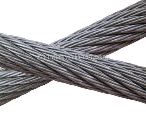
Rotation resistant wire rope refers to a series of steel ropes which minimizes the tendency to spin or rotation under load. These wire ropes boast special design - the outer layer is twisted in the reverse direction of inner layers for counteracting torsional forces generated from multi-layers of strands.
To achieve the resistance against the spin and rotation, all wire ropes are composed of at least two layers of strands. In general, more layers a rotation resistant wire rope has, more resistance it will boast. For example, 2-layer ropes is much easier to spin and rotate than 3-layer ones. Meanwhile, if one end of free rotation is allowed, 2-layer rope can only develop 55% to 75% of its breaking strength comparing with 95% to 100% of 3-layer ropes.
The 3-layer rope with more outer strands is capable to distribute more radial pressure onto inner layers and ideal for larger mobile such as all tower cranes.
Wire ropes with 8 to 10 strands & 2-layer constructions without reversely twisted inner strands have very similar appearance to rotation resistant wire ropes, but they are not.
Rotation resistant wire ropes are considered to be less stable needing to be handled and installed with great care. They must be taken to avoid high loads with small diameter sheaves.

There are many different sizes, configurations, and materials that form wire rope, and these are different types including stainless steel wire rope, galvanized wire rope, and bright wire rope.
Looking for accessories to use with wire ropes? Our rigging supplies include hardware and accessories for use with cranes, hoists & winches, and oilfield applications.
Diameter:To properly measure the diameter of steel wire ropes, measure the rope at its widest point. This is an industry standard with wire cable manufacturers and steel cable suppliers.
Grade of Steel – EIPS, EEIPS: EIPS is Extra Improved Plowed Steel and has roughly 10% more strength than IPS. EEIPS is Extra Extra Improved Plowed Steel and is approximately 10% stronger than the EIPS. We offer every variety of EIPS Wire Rope and have a one day lead time on any EEIPS ropes.
Direction of Lay: Right hand and left hand designates which way the strands wrap around the core of the steel rope. Regular lay and Lang lay specify which way the wires are formed in the helix pattern. Regular lay means the wires are rotated opposite the direction of the strands around the core. Lang lay means the wires are twisted in the same direction as the strands are wrapped around the wire rope core.
Finish – Bright Wire, Galvanized Wire, and Stainless Steel: Most wire ropes have a bright, self-colored finish hence the name. Wire ropes generally have a coating of lubricant to reduce friction and protect from corrosion. However, there are wire ropes that are galvanized, stainless steel, or coated in vinyl and other plastics.
Material of the Core: Fiber Core (FC) or Independent Wire Rope Core (IWRC) – Fiber cores are made of natural (sisal, etc.) or synthetic (polypropylene, etc.) fibers and allow for increased flexibility. IWRC offers more support to the outer strands, and have a higher resistance to crushing. IWRC also offers more resistance to heat, reduces the amount of stretch, and increases the strength of the rope.
Strands: Another variable in wire rope is how many strands make up the rope and how many wires make up one strand. For instance, a 6×26 wire rope has 6 strands around a core with 26 wires making up each strand. The 6×19 class is the most common and offers higher resistance to abrasion whereas the 6×37 class offers higher flexibility.
Although there are exceptions for special applications, the constructions in 6×36 classification are primarily designed to be the most efficient for each rope diameter. As the rope size increases, for instance, a large number of wires can be used to achieve required fatigue resistance, and still those wires will be large enough to offer adequate resistance to abrasion.
The 6×19 classification of wire ropes includes standard 6 strand, round strand ropes with 16 through 26 wires per strand. This is a good rope to withstand abrasion or crushing on the drum. Ropes with independent wire rope strands and a core (IWRC) in general, are more crush resistant than fiber core ropes.
When you purchase our 6×19 Class of wire ropes, you get more than just another rope. Manufactured in an ISO 9001 certified factory and backed by the industry’s largest staff of professional engineers, we do more than meet published specifications.
The 6×26 WS has better resistance to abrasion than a 6x25FW. It features a compact construction with solid support for the wires; therefore it has a high resistance to crushing. Its number and relative size of the inner wires add to the stability of the strand and gives it a fatigue resistance comparable to a 6×25 FW. A standard 6×26 WS construction provides the best rope for a wide range of applications. In general, we recommend the use of the 6x26WS in any application where a 6x25FW is used.
Mast Raising Lines, also called Bull Lines or Bridle Lines, are usually two pieces: each having sockets on both ends. These lines can be fabricated from either right regular lay rope or right lang lay rope. They must be fabricated from IWRC ropes.
Premium ropes may be used for specific applications. PFV cushions the strands, distributes internal stresses, keeps in wire rope lubricant and keeps out dirt and debris, extending the service life.
Flex-X® 9 features compacted strands and swaging for extra drum crushing resistance and increased stability. Its high-density strands deliver extra strength and resistance to abrasion. Flex-X® 9 is manufactured with a dual compaction process to produce a compact cross-section with minimum voids and greater surface area on outer wires that contact drums, sheaves and the rope, itself during operation. The high-density compacted strands minimize nicking at strand-to-strand contact points. Flex-X® 9 was specifically designed for boom hoist applications and tubing line applications where drum crushing is a challenge.
Flex-X® 6 users receive superior performance and increased service life in many applications compared to the ropes they had previously employed. When compared to conventional six-strand ropes, Flex-X® 6 ropes provide greater surface area and more steel per given diameter. This increases rope stability and strength. This results in a longer service life and less sheave and drum wear.
Flex-X® 19, a Category 2 rotation resistant rope, is made from 19 strands. Six strands are laid around a core strand in one direction, and then 12 strands are laid around this first operation in the opposite direction. Because of its tightly compacted smooth design, Flex-X® 19 offers more crushing resistance than standard 19×7 rope, higher strength-to-diameter, resistance to bending fatigue, exceptional stability, reduced wear to sheaves and drums, and improved handling, operating and spooling characteristics.

High strength 6-strand rope for applications which require a crush resistant rope to be used on multiple layer winding systems. Because constructional stretch is near zero it can be used where a "pre-stretched" rope would be required.
Super-8R is the next step up from regular 8x36 wire rope for overhead cranes with the ability to operate with fleet angles up to 4°. The 8-strand construction provides an excellent combination of flexibility and performance.
Super 8C is a classic "upgrade" rope for all overhead crane types for increased rope service life performance while maintaining the ability to operate with fleet angles up to 4°. The 8-strand construction provides an excellent combination of flexibility, fatigue life and abrasion resistance. This rope is also the idea choice for container- and port cranes. We can provide this rope in "dual-tensile strength" by which the outer strand wires are made from higher fatigue resistant steel.
Super 8V is an upgrade rope for all overhead crane types which require a stronger rope to increase the crane capacity while maintaining the ability to operate with fleet angles of up to 4°. The 8-strand construction provides an excellent combination of flexibility and abrasion resistance. Also used in looping- or accumulator tower applications.
Developed for maximum performance on overhead cranes. This rope features a plastic coated core for extended fatigue life performance and permanent core lubrication. Python® Multi is spin resistant to reduce block twisting on overhead cranes. Recommended for looping- or accumulator tower applications.
All steel high strength type for overhead cranes. This rope is swage compacted to enhance abrasion characteristic and to reduce sheave- and drum wear. Up to 40% strength increase over standard 6-strand constructions.
Ultra high strength type mainly used as high fatigue resistant rope for engineered cable assemblies. Up to 55% strength increase over standard 6-strand constructions. Sensitive to introduced rotation so call before you select this rope for overhead crane applications.
Very robust 4-strand wire rope which is compacted resulting in flat outer strands for increased abrasion resistance. This rope is spin-resistant and is used as hoisting rope for bulk ship cranes as well as on heavy duty construction equipment like pile drivers.
Same design geometry as 19x7 but due to a larger number of individual wires it is more flexible. The rope is strand compacted to provide for better drum spooling and less mechanical interlocking at the cross-over points. Recommended as standard rope type for Grove-, Terex-, National-, Century- and other US made truck- and mobile cranes. Python® Compac 18 is a rotation resistant rope and should only be used where these demands are low or moderate. NOT to be used in high cycle- high fatigue applications and NOT to be used with a swivel.
Recommended to be used on tower- and european type mobile cranes. Available in left- and right hand lay as well as in regular- and lang"s lay constructions. Recommended to be used in single line applications. ALLOWED to be used with a swivel.
Medium strength, high fatigue resistant non-rotating type. Compacting increases strength and sheave contact area. The plastic coated core increases fatigue life and prevents premature inner wire breaks as well as providing for permanent core lubrication. ALLOWED to be used with a swivel.Popular as ship crane main hoist rope.
High strength super flexible true non-rotating rope. Oval outer strands provide for excellent sheave and drum contact area. Lift has very successfully been used in multiple drum layer applications. Needs special attention during installation. ALLOWED to be used with a swivel.Used on many Manitowoc cranes.
Use the "rag-and-visual" method to check for external damage. Grab the rope lightly and with a rag or cotton cloth, move the rag slowly along the wire. Broken wires will often "porcupine" (stick out) and these broken wires will snag on the rag. If the cloth catches, stop and visually assess the rope. It is also important to visually inspect the wire (without a rag). Some wire breaks will not porcupine.
Measure the rope diameter. Compare the rope diameter measurements with the original diameter. If the measurements are different, this change indicates external and/or internal rope damage.
Visually check for abrasions, corrosion, pitting, and lubrication inside rope. Insert a marlin spike beneath two strands and rotate to lift strands and open rope.
Corrosion from lack of lubrication and exposure to heat or moisture (e.g., wire rope shows signs of pitting). A fibre core rope will dry out and break at temperatures above 120°C (250°F).
Kinks from improper installation of new rope, sudden release of a load or knots made to shorten a rope. A kink cannot be removed without creating a weak section. Discarding kinked rope is best.

If the steel wire rope is to be used in hazardous conditions a risk evaluation is to be done. The WLL of the steel wire rope should be decided or adjusted according to this. Example of such conditions are offshore, lifting people or dangerous load.


 8613371530291