
seizing wire rope ends free sample
Proper seizing and cutting operations are not difficult to perform, and they ensure that the wire rope will meet the user’s performance expectations. Proper seizings must be applied on both sides of the place where the cut is to be made. In a wire rope, carelessly or inadequately seized ends may become distorted and flattened, and the strands may loosen. Subsequently, when the rope is operated, there may be an uneven distribution of loads to the strands; a condition that will significantly shorten the life of the rope.
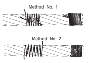
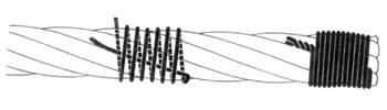
Either of the following seizing methods is acceptable. Method No. 1 is usually used on wire ropes over one inch in diameter. Method No. 2 applies to ropes one inch and under.
Method No. 1: Place one end of the seizing wire in the valley between two strands. Then turn its long end at right angles to the rope and closely and tightly wind the wire back over itself and the rope until the proper length of seizing has been applied. Twist the two ends of the wire together, and by alternately pulling and twisting, draw the seizing tight.
The Seizing Wire. The seizing wire should be soft or annealed wire or strand. Seizing wire diameter and the length of the seize will depend on the diameter of the wire rope. The length of the seizing should never be less than the diameter of the rope being seized.
Proper end seizing while cutting and installing, particularly on rotation-resistant ropes, is critical. Failure to adhere to simple precautionary measures may cause core slippage and loose strands, resulting in serious rope damage. Refer to the table below ("Suggested Seizing Wire Diameters") for established guidelines. If core protrusion occurs beyond the outer strands, or core retraction within the outer strands, cut the rope flush to allow for proper seizing of both the core and outer strands.

After cutting the rope (see below) it is good practice to braze PYTHON®, 19×7, and 34×7 rope ends to ensure that they don’t unravel. Leave the seizings on the rope for added holding strength. Be careful not to damage the seizing while brazing.
We found that blade cutting a rope gives the best results. Be sure to use a cutting blade suitable for the job (We use cutting blades made by ‘PFERD-HORSE’ type ELASTIC # 80 EHT 230-2 A 24 SG INOX.) Follow the safety precautions for free hand cutting.

To prevent the unlaying/ loosening of the wire rope strands ( or brooming ) when we perform cutting on the wire rope, binding of a wire material ( also known as seizing wire) on each side of the wire rope ( to be cut ) is usually necessary.

I used to be doubtful about the necessity of seizing shackles. Nip the pin up tight with a shackle key or pliers and how can it possibly come loose? My mind was changed in 2011, while checking the rig of the old Jeanneau we used in our Crash Test Boat series. This was the rather concerning sight we found at the masthead.
We use one of three methods of seizing, or securing, the pin to ensure that it simply can’t loosen. One is using threadlock, which glues the pin in place but not with ‘super-glue’ adhesion so it can still be undone with standard tools.
A second method is using electrical cable ties, though it is worth remembering that these are subject to UV degradation and probably won’t last more than a season if they’re always out in the sun. The third method, the gold standard method of seizing shackles, is to use Monel wire. That isn’t subject to UV degradation and has excellent corrosion resistance properties.
Poke the wire up through the hole in the shackle pin then down through the shackle itself and repeat so you have two loops of wire around the shackle and through the pin
Rigging equipment has a tough job lifting and moving heavy loads for hours and hours a day. In order for that equipment to be able to be its job, we have to take proper care of it. We expect longevity and endurance from equipment like wire rope, but that can easily turn if not properly treated. Equipment that is properly treated, handled, installed, inspected and stored will reward us with a prolonged life of service, better job performance and peace of mind in knowing it won’t fail.
Riggers don’t have the luxury of simple equipment slip-ups. If your rigging equipment fails you, it can cause damage to product, property and worst-case scenario, an extreme safety hazard resulting in injury or loss of life. Since wire rope is a material of choice in heavier lifts, extreme safety hazards can be a real possibility if you’re using rope that’s in an unsafe condition.
Seizing and cutting operations are not difficult to perform, but are crucial in the performance of wire rope. Proper seizing must be applied to both rope ends to protect the wire ropes from loosening – Carelessly or inadequately seized ends may cause distortion or flattening of the rope. If you use wire rope that is not properly seized it will cause uneven distribution of the load over the strands causing the life of the wire rope to be drastically shortened.
Normally, one of two methods are used to do this. Typically method one is suitable for wire ropes with a diameter over one inch, and method two is those with a diameter one inch and under.
If you’re dealing with loading or unloading wire rope in a reel or coil, it’s important to know that that is not a protected storage method and if you drop the reel during this process, it can lead to serious damage to your wire rope. Because of this, it is important to handle reels of wire rope with care and focus not to drop or damage the reel. Damage to the reel can also make it incredibly difficult to remove the wire rope from the reel, so it’s not only an important safety precaution but will also save you time and frustration in the future.
It’s also important to take care when removing wire rope from the reels or coils. When doing this, ensure the reel or coil is rotating as the wire rope unwinds. Below you will see some of the rights vs. wrongs for unwinding rope.
In the rigging field, it’s very important that workers be properly trained in any and all tasks they are performing because many lifts can become extremely dangerous if even one aspect is done incorrectly. So the most important thing to take away from this tip is to seek out proper training from certified professionals before taking on tasks like installing wire rope!
Once you have that training you will know how important it is to take into account the design factor of any equipment being used with wire rope, being sure to take note of the nominal diameter of wire rope to use with the equipment, as specified by the manufacturer. Installing an incorrect size will result in a failed rope or shorter service life as the rope can get pinched into a smaller space compromising its integrity.
Wire rope diameter is determined by measuring the outer circle of the strands, which is the greatest dimension that can be measured with a pair of parallel-jawed calipers or machinist’s caliper square. You can easily make a mistake if not taking care in measuring the largest dimension, as shown below:
Keeping up with the required inspections is something that must be prioritized for all rigging equipment. Wire rope is often used for heavy lifting, which means they are being used in situations where they are trusted to keep not just your load safe, but the people and the environment around it. That means that you have to be confident that your wire rope is up to the task – And how do you do that? Inspections!
Based on manufacturer/organization recommendations, ensure your wire rope is being inspected by a certified professional where the rope can be dismantled and tested through visual assessment and non-destructive testing. Hercules SLR can make this a worry-free part of your business – Our experience and LEEA certified team can take this completely off your hands, on-site or in our fell service rigging shops!
On top of these professional inspections, wire rope should also be visually assessed by trained and experienced workers at the start of every shift or when resuming stalled work. Thorough visual assessments should also be carried out after reattaching or refitting the wire rope on the same or different equipment. Machine operators should be trained to visually assess the entire wire rope, with emphasis on points of attachment.
Things to look for when visually assessing a wire rope: Broken Strands– One of the easiest ways to do this is to run a cotton cloth over the length of the wire (if possible), checking for any places where the material get’s snagged. Any cable that has a single broken wire strand located around critical fatigue areas (where the cable runs around a pulley, sleeve or through a fair-lead; or any section where the cable is flexed, rubbed, or worked) must be replaced. Generally, SOME broken wires in non-critical areas are okay, but always consult your service/maintenance manual.
https://gfycat.com/naturalsilverhawk-skycatcher-stationair-inspection-propeller Internal Ware and Tare – It is recommended to remove the cable whenever possible and flex them to ensure that all cables on the inside of the wire rope haven’t worn down due to environmental deterioration, distortion or fatigue. If you haven’t been keeping up with regular inspections, this is particularly necessary as it is possible for wire rope to look completely sound from the outside, but as soon as you move it around, it completely fails.
Wire rope needs to be stored in a well-ventilated, dry, and covered area and should not come in contact with the floor. If it is necessary to store it outside, they must be covered so that moisture cannot get inside and cause corrosion. You should also make sure that they are protected from dust, water, steam, salt, chemical fumes or adverse climatic conditions.
Turning the reel occasionally is a good practice to get in the habit of. This will prevent the wire rope’s lubricant from wearing off. If ropes are stored for a long time, it is advised for you to get them examined periodically and apply a coat of lubricant to them.

Whatever cutting methods your applied, certain precaution - seizing both rope ends must be employed to protect the steel wire ropes from loosening. But carelessly or inadequately seized ends may cause distortion and flattening of the rope. If these loose ropes are applied to works, uneven distribution of loads to the strands may shorten the life of ropes badly. So it is important to seize the wire ropes in the optimal way.
Normally, two methods are widely accepted by our customer. The method one is suitable for wire ropes with diameter over one inch, while the method two is for those with diameter one inch and under.
The diameter and length of seizing wires may different as the diameter of the wire rope. Make sure that the seizing length is no less than the diameter of the steel wire rope.
Generally, one seizing on each side of the cut is sufficient for preformed ropes. But for rotation resistant or non-preformed ropes, no less than two seizing parts are needed with the distance about six rope diameters.

6-1. INTRODUCTION. Section I of this chapter discusses blocks which are among the most important fittings used aboard ship on the deck, in the engine department, and in other operations. Section II covers elements of wire rope rigging which cargo handlers in a terminal service company must know. It details the care and use of wire rope, procedures for computing the safe working load and breaking strength, and inspection and handling. Section III covers marlinespike seamanship, which is a general term for handling and caring for fiber line and wire rope used aboard ship or in other marine operations.
b. Every tackle system contains a fixed block attached to some solid support and may have a traveling block attached to the load (see Figure 6-4). The single rope leaving the tackle system is called the fall line. Personnel apply the pulling force to the fall line which may be led through a leading block.
b. The size metal block to use with wire rope depends on the diameter of the sheave. The sheave is never less than 20 times the diameter of the wire. For example, personnel can determine the size block to use with 3/4-inch wire rope as follows:
6-8. REEVING TACKLES. Personnel reeving tackles reeve each type differently. If a tackle is rove improperly, too much friction and possible binding of the falls can result when lifting or lowering a load, creating a safety hazard. It is important to use the proper method of reeving each type of tackle up to and including a threefold purchase.
* This table is computed in pounds for new line. For line that has been used these figures will decrease. Old line may have only 60 percent of the strength shown in pounds for a given size of line.b. To determine the SWL for a line of known size to be rove into a tackle, personnel should use one of the following formulas as appropriate, where "C" denotes circumference and "D" denotes diameter. The formulas for manila and nylon will give the SWL in pounds. The formulas for wire rope will be in tons.
c. If personnel are unsure which type of wire rope they are using, they must always use the formula for mild steel when figuring the SWL. This will ensure ultimate safety since the different strengths of wire rope cannot be identified visually.
6-12. CARE AND USE OF WIRE ROPE. Wire rope is made of steel except for its core which is likely to be fiber. The grades of wire rope in descending order of strength are: Extra improved plow, improved plow, plow, and mild plow steel. Of these four grades, the Army uses improved plow steel extensively and plow steel to a lesser extent. The manufacturer stamps the grade on the reel. Because the grade of wire rope is not visually apparent, it should always be considered as plow steel when in doubt.
6-13. MAKEUP OF WlRE ROPE. The basic unit of wire rope is the individual wire. Wires are laid together to form strands. The number of wires in a strand varies according to the purpose for which the rope is intended. Strands are laid around a core to form the wire rope itself. With preformed plow steel wire rope, the core may be hemp or polypropylene, a synthetic fiber. The core is a foundation to keep the wire rope round, to act as a shock absorber when the wire rope contracts under strain, and to serve as a reservoir for lubricant. Figure 6-7 shows a cross section of wire rope.
b. Strand Construction. In most wire rope used today, the wires and strands are preformed. Preforming means presetting wires in the strands into a permanent corkscrew form which they will have in the completed rope. As a result, preformed wire rope does not have the internal stresses found in nonpreformed wire rope, does not untwist as readily as nonpreformed wire rope, and is more flexible.
c. Types of Lay. Lay refers to the direction of winding of the wires in the strands and the strands in the rope. Both may be wound in the same direction or in opposite directions.(1) In regular lay, the strands and wires are wound in opposite directions. Most common is the right regular lay in which the strands are wound right and the wires wound left. This lay is used in marine operations.
6-15. MEASUREMENT. Whatever its grade, wire rope is usually measured by its diameter. Figure 6-8 shows the correct method of measuring the diameter of wire rope. To measure wire rope correctly, personnel should place it in the caliper so that the outermost points of the strands will be touching the jaws of the caliper.
6-16. SAFE WORKING LOAD AND BREAKING STRENGTH. The SWL and BS formulas are listed in the paragraphs below.a. Formulas for determining the SWL of several grades of wire rope have constants that are not to be confused with safety factors. For example, the formula for the SWL in STONs (2,000 pounds) for extra improved plow steel wire rope is diameter squared multiplied by 10, or SWL = D2 x 10. The formula to find the SWL of 1-inch, 6 x 19, extra improved plow steel wire rope is as follows: SWL = D2 x 10 = 1 x 1 x 10 = STONs.
b. A figure relatively constant in marine operations, especially for new wire rope, is the SF, which is 5. The SF is used with the SWL to find the BS.
6-17. INSPECTION OF WIRE ROPES. Wire ropes should be inspected frequently and replaced if frayed, kinked, worn, or corroded. The frequency of inspection depends on how often the rope is used. Wire rope used 1 or 2 hours a week requires less frequent inspection than one used 24 hours a day.a. Common causes of wire rope failures are as follows:Using rope of incorrect size, construction, or grade.
b. Carefully inspect weak points and points of greatest stress. Worn or weak spots show up as shiny, flat spots on the wires. If the outer wires have been reduced in diameter by one-half, the wire rope is unsafe.
c. Inspect broken wires, since they show where the greatest stress occurs. If individual wires are broken next to each other, unequal load distribution at this point will make the rope unsafe. Broken wires are called fishhooks. To determine the extent of damage to the wire rope, users can slide a finger along one strand of wire for one complete turn, equal to the length of one wire rope lay. Next, count the number of fishhooks. If six or more fishhooks are discovered, the wire rope is unsafe and should be replaced immediately.
6-18. HANDLING. There are different handling methods for wire rope. These methods are listed below.a. Kinking. When loose wire rope is handled, small loops frequently form in the slack portion of the rope. If personnel apply tension to the rope while these loops are in position, the loops will not straighten out but will form sharp kinks, resulting in unlaying of the rope. Personnel should straighten these loops out of the rope before applying a load. After a kink has formed in wire rope, it is impossible to remove it, and the strength of the rope is seriously damaged at the point where the kink occurs.
b. Unreeling. When removing wire rope from a reel or coil, personnel should be sure to rotate the reel or coil. If the reel is mounted, the wire rope may be unwound by holding the end and walking away from the reel. If a wire rope is in a small coil, personnel may stand the coil on end and roll it along the deck, barge, wharf, or ground. Remove any loops that may form, although rotating the reel or coil usually avoids causing loops to form.
c. Seizing. Personnel should seize (lash together) all wire rope before cutting it. If the ends of the rope are not properly secured, the original balance of tension is disturbed. Maximum use cannot be made on wire rope when some strands carry a greater load than others.
(2) There are three formulas for determining the number and length of seizings and the space between them. When a calculation results in a fraction, the next larger whole number is used. The following formulas are based on a 3/4-inch diameter wire rope.(a) The number of seizings required equals about three times the diameter of the rope. For example: 3 x 3/4 = 2 1/4 or 3 seizings. Because the rope will be cut, six seizings are required so that there will be three on each rope end after the cut.
d. Cutting. Wire rope may be cut with a wire rope cutter, a cold chisel, a hacksaw, bolt clippers, or an oxyacetylene cutting torch. When cutting wire rope, personnel should follow the procedures outlined below.(1) To seize the wire rope, insert it into the cutter with the blade between the two central seizings, close the locking device, then close the valve on the cutter. The handle should be pumped to build up enough pressure to force the blade through the rope.
(2) Use the bolt clippers on wire rope of fairly small diameter. Use the oxyacetylene torch on wire of any diameter. Cutting with the hacksaw and cold chisel is slower than cutting with the other tools and equipment.
e. Coiling. Personnel may need to take a length of wire rope from a reel and coil it down before using it. Small loops or twists will form if the wire rope is coiled in a direction opposite to the lay. To avoid loops, users should coil right lay wire rope clockwise and left lay wire rope counterclockwise. When a loop forms in the wire, they should put a back turn in as shown in Figure 6-10.
Figure 6-10. Putting a back turn in wire ropef. Size of Sheaves and Drums. When a wire is bent over a sheave or drum, two things happen: Each wire is bent to conform to the curvature, and the wires slide against each other lengthwise because the inside arc of the rope against the sheave or drum is shorter than the outside arc. The smaller the diameter of the sheave or drum, the greater the bending and sliding. Personnel should keep this bending and moving of wires to a minimum to reduce wear. The minimum recommended sheave and drum diameter is 20 times the diameter of the rope. For example, for 5/8-inch rope: 20 x 5/8 = 12 1/2-inch sheave. If a 12 1/2-inch sheave is not on hand, personnel should use the next larger size, never a smaller size.
g. Lubrication. Wire rope is lubricated as it is manufactured. The lubricant generally does not last throughout the life of the rope, which makes relubrication necessary. Crater "C" compound is recommended, but personnel may use oil on hand rather than delay lubrication. Crater "C" compound should be heated before it is put on the wire rope. Personnel should use a brush if possible to apply lubricant. If a brush is not available, they may use a sponge or cloth, but they should look out for fishhooks or broken wires.
h. Reversing Ends. It is sometimes advisable to reverse or cut back ends to get more service from wire rope. The wear and fatigue on a rope frequently is more severe at certain points than at others. Reversing distributes stronger parts of the rope to the points getting wear and fatigue. To reverse ends, personnel remove the drum end, put it in the attachment, and then fasten the end taken from the attachment to the drum. Cutting back the ends has a similar effect, but not as much change is involved. In reversing ends, personnel should cut off short lengths of both ends to remove the sections with the greatest local fatigue.
i. Storing. Wire rope should be coiled on a spool for storage. Its grade, size, and length are noted on a tag attached to the rope or spool. Wire rope should be stored in a dry place to reduce corrosion. Personnel should not store it with chemicals or where chemicals have been stored because chemicals and their fumes can attack the metal. Personnel should always clean and lubricate wire rope before storing it.
j. Cleaning. Personnel can remove most of the dirt or grit on a used wire rope by scraping or steaming. Rust should be removed at regular intervals by wire brushing. Personnel must clean the rope carefully before lubricating to remove foreign material and old lubricant from the valleys between the strands and from the spaces between the outer wires. This permits the newly applied lubricant to freely enter the rope.
6-19. CHARACTERISTICS AND FIBER LINE. To be able to work with fiber line, personnel must know its characteristics and properties. They must be able to handle and care for the line, and tie basic knots, bends, and hitches.a. Materials for Fiber Line. Fiber line is made of either vegetable or synthetic fibers. Vegetable fibers include manila, sisal, hemp, cotton, and flax. Synthetic fibers include nylon, Dacron, polyethylene, and polypropylene. The Army primarily uses nylon synthetic fiber line, so this manual covers only that synthetic fiber.(1) Manila is a strong fiber that comes from the leaf stems of the abaca plant, a part of the banana family. Varying in length from 4 to 15 feet in their natural state, the fibers have the length and quality which gives manila rope relatively high elasticity, strength, and resistance to wear and deterioration.
(3) Hemp is a tall plant that has useful fibers for making rope and cloth. It was used extensively before manila was introduced. Now hemp"s principal use is in fittings such as ratline and marline. Because hemp is absorbent, the fittings are tarred to make them more water-resistant.
b. When any unsatisfactory conditions are found, destroy the line or cut it in short pieces. Make sure that none of these pieces is long enough to permit its use. This not only prevents the use of line for hoisting, but saves the short pieces for miscellaneous use such as lashings, whippings, and seizings.
6-23. WHIPPING LINE. Personnel must never cut a line or leave the end of a line dangling loose without a whipping to prevent it from unlaying. A line without whipping will unlay of its own accord. Whenever a line or hawser has to be cut, whippings should be put on first, on each side of the cut. To prevent fraying, a temporary or plain whipping can be put on with any type cordage, even rope yarn. Figure 6-12 shows one of the several methods that can be used for putting a temporary whipping on a line.
6-24. KNOTS, BENDS, AND HITCHES. Each of the three terms-knot, bend, and hitches-has a specific definition. The choice of the best knot, bend, or hitch to use depends largely on the job it has to do. In a knot, a line is usually bent or tied to itself, forming an eye or a knob or securing a cord or line around an object, such as a package. A good knot must be easy to tie, must hold without slipping, and must be easy to untie. In its noun form, a bend ordinarily is used to join the ends of two lines together. In its verb form, bend means the act of joining, bent is the past tense of bend. A hitch differs from a knot and a bend in that it ordinarily is tied to a ring, around a spar or stanchion, or around another line. It is not merely tied back on itself to form an eye or to bend two lines together. This portion of the manual explains why a given type is used and also gives the efficiency or strength of many of the knots, bends, and hitches.
Figure 6-15. Figure eight knotc. Square Knot. Personnel use the square knot to tie two lines of equal size together so that they will not slip. Figure 6-16, shows that in the square knot the end and standing part of one line comes out on the same side of the bight formed by the other line. This knot will not hold if the lines are wet or are of unequal sizes. It tightens under stain but can be untied by grasping the ends of the two bights and pulling the knot apart. Its strength is .45 percent. To avoid a "granny" or a "fool"s knot" which will slip, personnel should follow this procedure: Pass the end in your right hand over and under the part in your left hand as illustrated in Figure 6-16. With your right hand, take the end that was in your left hand and pass the end under and over the part in your left hand.
e. French Bowline. A French bowline is used as a sling for lifting an injured person. For this purpose one loop is used as a seat and the other loop is put around the body under the arms, with the knot drawn tight at the chest. Even an unconscious person can be hoisted safely in a properly secured French bowline, because the weight applied will keep the two loops tight so that the individual will not fall out. Personnel must not allow the loop under the person"s arms to catch on any projections. The French bowline may also be used if a person is working alone and needs both hands free. The two loops of the knot can be adjusted to the required size. Figure 6-18 shows the step-by-step procedure for tying the French bowline.
Figure 6-20. Clove hitchh. Stopper Hitch. A slight defect of a clove hitch is that it can slide along the cylindrical object to which it is tied. To guard against this, personnel should use a stopper hitch (commonly called a rolling hitch) which is illustrated in Figure 6-21. This figure shows fiber rope; with wire rope, personnel would use a small chain.
6-25. SPLICING THREE-STRAND FIBER LINE. Splicing is a method of permanently joining the ends of two lines or of bending a line back on itself to form a permanent loop or an eye. If two lines are to be spliced, strands on an end of each line are unlaid and interwoven with those of the standing part of the line. Small stuff can be spliced without a fid, which is a tapering length of hard wood used in splicing larger lines. A knife is used to cut off the ends of the strands.a. Short Splice. The short splice is as strong as the rope of which it is made. However, the short splice increases the diameter of the rope and can be used only where this increase in diameter will not affect operation. The splice is frequently used to repair damaged ropes or where two ropes of the same size are to be joined together permanently. Damaged parts of the rope are cut out and the sound sections are spliced. Personnel should follow these steps-(1) Untwist one end of each line five complete turns. Whip or tape each strand. Bring these strands tightly together as in Figure 6-22, view 1, so that each strand of one line alternates with a strand of the other line. Put a temporary whipping on the lines where they join to keep them from suddenly coming apart. Do this procedure with small lines until you are skilled enough to hold them together while you tuck.
b. Eye Splice. When a permanent loop is to be put in the line, personnel should use an eye splice which has a strength of 90 to 95 percent. (Compare this with the strength of a bowline which is 60 percent.) Personnel should follow these steps:(1) Unlay (untwist) the strands in the end of the line four or five times and splice them into the standing part of the line by tucking the unlaid strands from the ends into the standing part. Whip or tape the ends of the strands. An original round of tucks, plus two more complete rounds, is enough. If the line parts, it will likely part in the eye rather than in the splice, so three rounds are as effective as a greater number.
(2) Always whip or tape the ends of the strands before starting, otherwise, they will unlay and be troublesome. Seize large lines at the point where unlaying stops to avoid trouble working with them. For lines with up to 21 threads, you can open the strands in the standing part with your fingers. Use the fid for larger lines.(a) Figure 6-23 shows how to make the first two tucks. Separate the strands in the end and hold them up as shown in the first step. Place the three unlaid strands against the standing part where they will be tucked, forming the desired eye. The middle strand facing you always tucks first. Put a reverse twist on the standing part so that you can raise the strand under which you will make the first tuck. Pick up the stand to be tucked, and tuck it under the strand raised. Always tuck from right to left or with the lay of the line.
6-26. PUTTING AN EYE IN WIRE ROPE. This paragraph discusses how to put both a temporary eye and a permanent eye in wire rope. A temporary eye can be put in wire rope by using wire rope clips or by using a field expedient known as a "hasty eye" or "Molly Hogan" splice. A liverpool splice is the accepted method for putting a permanent eye in the end of a wire rope. With the proper equipment, and a bit of practice, a liverpool splice can be put in wire rope in less than 15 minutes.a. Splicing Tools. With the exception of the wire cutters, Figure 6-24 shows the tools needed for splicing. The marlinespike is used for opening the strands in the standing part of the wire rope and for working the strands to be spliced into the standing part. The wire cutters are used for cutting the strands after the splice is complete. The hydraulic wire rope cutter is used to cut the length of wire rope that will be spliced. A thimble is used to keep the wires from moving and the rigger"s vise from crushing them when a soft eye is made. After the soft eye is spliced, the thimble is removed. When an eye is to have a thimble as a permanent part, the thimble is the size of the eye desired.
b. Temporary Eye. A temporary eye may be put in wire by using wire rope clips. Figure 6-25 shows the correct way of using these clips. As the illustration shows, a wire rope clip consists of two parts: the U-bolt and the roddle, the part into which the U-bolt is inserted. Personnel should always put the U-bolt over the bitter end and the roddle on the standing part. This procedure protects the live or stress-bearing end of the rope against crushing. The roddle protects the rope and, therefore, should always be placed against the live end.(1) To obtain maximum strength from the temporary eye splice, use the correct size and number of wire clips, and the correct spacing between them. Size is stamped on the roddle between the two holes. Personnel may use the following formula to determine the number of clips: 3 x diameter of wire rope + 1 = number of clips. For example, the number of clips needed for l-inch wire rope is: 3 x 1 + 1 = 4. To determine the correct space between clips, multiply the diameter of the rope by six. For example, the space between clips to be put on 1-inch rope is: 6 x 1 = 6 inches. Measure the space from the center of one clip to the center of the next one. If the calculation for either the number or the space results in a fraction, round off to the next higher whole number.
(2) The improved type of wire rope clips shown in Figure 6-26 has a few advantages over the older type. Both halves are identical and provide a bearing surface for both parts of the rope. Thus, it cannot be put on wrong and does not distort the wire. It also allows a full swing with a wrench.
c. Hasty Eye (Molly Hogan) Splice. Occasionally it becomes necessary to construct a field expedient, called the hasty eye or Molly Hogan splice. This splice can be quickly made, but it is limited to about 70 percent of the strength of the wire rope. It should not be used to lift heavy loads. This splice can be used only when working with preformed wire rope. To make a hasty eye splice, personnel should follow these steps:(1) Using a marlinespike, screwdriver, or, if necessary, a nail, separate the wire rope into two three-strand sections. These sections should be unlaid four times the diameter of the desired eye. If you want a l-foot diameter eye, unlay the sections back 4 feet.
d. Liverpool Splice. The liverpool splice is the easiest and most common of the wire splices to make. It is the primary splice used when a permanent eye is required. Personnel should follow these instructions:(1) Forming the eye. To find the distance, the strands should be unlaid for an eye splice; then, multiply the diameter of the wire by 36 inches. (For example, to determine the distance of a 5/8-inch wire rope: multiply 5/8 x 36/1 = 180/8 = 22 1/2 or 23 inches.) Measure off that distance on the wire rope and put a seizing at that point. Cut the end seizing and carefully unlay the strands. Whip the ends of each strand with either sail twine or friction tape. Form the desired size eye and put the eye in the rigger"s vise with the unlaid strands to your right as you face the vise. Stretch out the standing part of the wire, clamp and lash it and you are ready to start.
NOTE: When splicing wire, always insert the marlinespike against the lay of the wire, and make sure not to shove it through the core. The core must be on the left-hand side of the spike.(2) Making the first tuck of strands one, two, and three. In the liverpool splice, the first strand goes under three strands, the second strand goes in the same opening but only under two strands, and the third strand goes in the same opening but only under one strand. All of the strands go in at the same point, but come out at different places (Figure 6-27). At this time, run the spike behind the three strands under which the first three are tucked, but above the first three tucked strands. Holding the marlinespike at a 90-degree angle to the standing part, turn the spike counterclockwise about one fourth of a turn and insert the core through the standing part. This is called "dipping the core." Make sure that the core is inserted under the marlinespike. Pull the core down and run it down into the splice.
(5) Tucking strands one, two, and three. To finish the splice, tuck number three, two, and one. Each is tucked three times in a row, ending up with an overall total of four tucks for each. To avoid kinking the strands on the last tucks, insert the spike and run it up the wire. Follow the spike up with the strand, shove it under the spike, and pull taut. Keeping a strain on the strand, work the spike and strand back around and down together. Hold the strand there and work the spike back up the wire. Follow up with the strand and take the last tuck. Work the strand back down and hold it there. Before pulling out the spike, run it back up until the strands of the standing wire bind the working strand in place. Make the second and third tucks with the remaining strands in the same way.
(6) Completing a splice. Remove the wire from the vise, use a hammer to pound the splice into shape, and cut off the ends of the tucking strands close to the splice.


 8613371530291