
shock loading wire rope factory
Shock loading can occur in any situation where the load on the crane suddenly increases. The crane and accessories are designed to take up the weight of loads gradually and steadily. They are not designed to withstand sudden increases or decreases in the apparent weight of the load. Some examples of how shock loading can occur are shown below.
Operators and equipment owners should be aware of the causes and potential dangers of shock loading. Because the equipment is being used in a way that it is not designed for, shock loading can lead to damaging the equipment, the facility, or injuring personnel. Understanding the causes of shock loading will help to prepare operators to safely and accurately operate the equipment.
Skilled operators are a company"s first defense against shock loading. Lifting and lowering should always be done in slow speed until all slack has been taken out of the wire rope and any below the hook devices. Additionally, operators should be aware of their surroundings, making sure that the load they are lifting is not likely to snag on other pieces of machinery or the building itself. When lifting or lowering the load, operators should be careful to make sure the load is not bouncing as they operate the hoist. Additionally, operators should ensure that their loads are secure and well balanced.
Beyond operator training and best practices, features such as the HoistMonitor®assist operators in preventing shock loads. The HoistMonitor ensures that starting and stopping is initiated in slow speed, which helps prevent a jumping motion of the load. Sudden load supervision, also a standard feature of the HoistMonitor, prevents the hoist from continuing the hoisting motion when a load increase is suddenly detected, like if the load snagged on another item.

Before we address shock loading let us take the time to understand the difference between static and dynamic forces. Static force is stationary. Static force usually refers to an object not in motion. Whereas dynamic force refers to an object that has unequal forces acting upon it. Rapid acceleration in lifting and rapid deceleration in lowering of a small or large load can result in what is often referred to as dynamic load.
Remember Newton"s second law? F = ma Force equals mass times acceleration. Acceleration refers to a change in the rate of velocity. Assuming we are referring to the same mass (size of the object), we see that the force exerted on an object is proportional to the acceleration it is given. This is the basis of the phenomena known as shock loading.
Generally speaking shock force or shock loading occurs when an operator takes up sling slack rapidly or suddenly releases the load creating a sudden jerk. Both rapid acceleration and deceleration of a load can create a shock force that far exceeds the working load limit of the wire rope. Always remember that the sudden release of a load can cause internal and external damage to a wire rope. Why is the safe working load limit of rigging slings and crane lines significantly lower than their minimum breaking strength? A safety factor must always exist. Remember that minimum breaking strengths are stated for static, straight lifts or pulls.
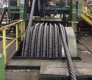
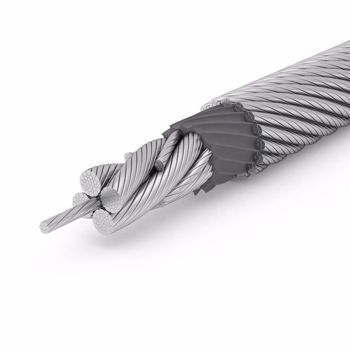
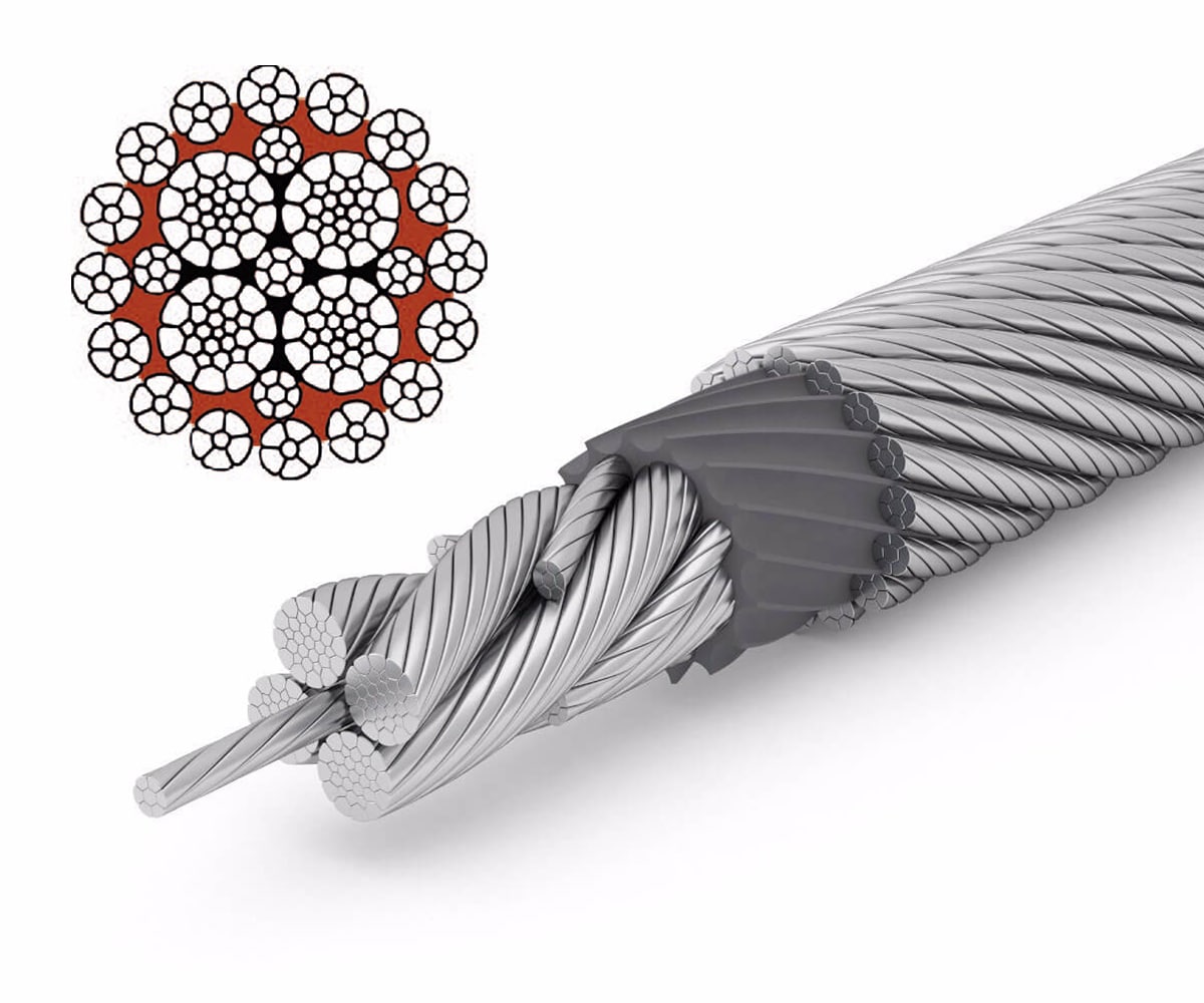
The four pictures in this post clearly illustrate what shock force or shock loading will do to a wire rope. Note the one strand has become unraveled from the other strands in forming the wire rope. Look closer and you will note broken wires at different points of the strand. Remember a series of individual wires make up each strand on a wire rope.

When overloads and shock loads occur in a rigging operation, the results can be deadly. A failure of gear or equipment can take place at the time the over/shock load happens or in many cases weeks, months or years later.
Most of us are familiar with the statistics used in rigging books and charts on the affects of shock loading. When a load of “X” pounds is allowed to free-fall or is popped off the ground, it introduces a load to the lifting device which can be two times or more its static weight. This compounding of weight takes its toll on the load’s internal and external structure, rigging attachment points, all rigging hardware, slings, hoist hook, running ropes, drum and entire hoisting system whether overhead or mobile crane.
A typical method of shock loading results from turning or flopping a load over from one plane to another. (Actual case) A coal-fired steam plant uses pulverizer journal assemblies to crush the coal into a fine talc - like powder for burning. The journals are awkward and difficult to handle with no available lifting lugs. After a journal is pulled from service and it has received maintenance, it is transported back to the pulverizer unit. A bridge crane picks up the journal from its vertical carrying cradle and sets the base on the floor. The crane then trolleys to pull or “flop” the journal over to a 45 degree angle. A special sling assembly is then used to hoist the journal into the pulverizer cavity.
During the “trolley and flop” movement, the slamming of the journal arms into their chain slings sends dust and dirt flying off the overhead bridge crane. How much weight in real pounds was introduced to the crane? Has anything happened to the crane’s structure? Does anyone suspect a broken weld, metal fatigue fracture or that damage has possibly occurred to the hoist system or wire rope? What if this happens twice a month for four years? Your imagination can provide many unwelcome answers to these questions.
Have you ever heard an employee say, “We were only lifting 2 tons on our 5 ton bridge crane and the whole thing came down on top of us!” Was it the 2 ton lift that caused the accident? Certainly not! It was the four years of repeated abuse, shock loading and structural damage which turned a fine bridge crane into a life threatening bucket of bolts.
If you have these situations in your operation, do everything possible to develop alternative rigging methods. Make a comprehensive inspection of all hoisting and rigging components. Using the proper procedures for each type of equipment perform load tests and make another inspection to ensure reliability. (Always check with the equipment manufacturer for testing procedures and limitations.)

Done properly, it is better than standard lifting gear that is required and this must be compliant for a special lifting environment – another thing to remember!
Not really – a special lifting environment is a predictable scenario and should be accounted for… but if overloading occurs sometimes the after effects can look pretty similar. There are lots of reasons for shock loading, but there are basically two types of shock loading. These are:
There are two basic damage mechanisms. The simplest of these is overloading. At some point the ‘shock’ exerts a peak force that is sufficient to damage something.
- A jib arm might be built to resist downward loads very well, and although it should be built very stiff it will still deflect under load. This means that if the load is released rapidly, there is stored energy in the jib and it can flick back up – loading it in reverse!
- A lifting system might have different parts which share the load forces, but which react to those forces at different rates. A classic example being a rotation resistant rope. If the load share on the rope core is applied or released too fast then the core no longer shares load with the strands and the resultant imbalance can cause the rope to have a hernia – which we call a ‘birdcage’.
The right rigging gear, and the right advice is the starting point for safe lifting and avoiding many things which can lead to shock loading. Nobles can supply you with the right lifting gear, the best inspection and maintenance services, and the right advice. We also offer loadcells and engineering services to analyse the lifting gear design, the lift study, and (should the worst occur) the aftermath – with scientific investigation of shock load damage.

MLA style: "Understanding shock loads.." The Free Library. 2013 United States Institute for Theatre Technology, Inc. 10 Dec. 2022 https://www.thefreelibrary.com/Understanding+shock+loads.-a0332379147
Chicago style: The Free Library. S.v. Understanding shock loads.." Retrieved Dec 10 2022 from https://www.thefreelibrary.com/Understanding+shock+loads.-a0332379147
APA style: Understanding shock loads.. (n.d.) >The Free Library. (2014). Retrieved Dec 10 2022 from https://www.thefreelibrary.com/Understanding+shock+loads.-a0332379147

To understand shock forces you must know that there exists static (not in motion) forces, and dynamic (in motion) forces. In the real world we rarely have just simply static forces occurring during lifts. Even small amounts of speeding up or slowing down of the load result in dynamic loads. The very act of even slow lifting often results in some forces caused by movement such as swinging and drifting.
However, the force we are talking about it the one that occurs rapidly as opposed to slow dynamic forces. Shock force is more commonly referred to as shock load. This derives from the fact that engineers routinely refer to forces occurring in and on structural members as loads. In rigging a load is an object to be lifted or flown from one point to another point, hence the use of the phrase shock force in this article.
Shock forces can occur for any number of reasons, most notably; an operator taking up sling slack with a sudden jerk, the rapid acceleration or deceleration of the load, failure of fair leads or sheave guides to prevent the rolling out of a slack line.
The magnitude of a shock force can be many times that of the weight of the load be lifted. This is why the safe working load of rigging equipment is substantially lower than the minimum breaking strength. Minimum breaking strengths are stated for static, straight pulls. A factor of safety must therefore exist.
The amount of force created in a shock situation is dependent on, among other things, the weight of the load and the distance of travel. The exact determination can be quite complicated because the value of the load"s stopping distance is based on the amount of elastic stretch.
In order to precisely calculate the stopping distance we would need to know the exact composition of the wire rope, the equivalent cross sectional area, and the apparent modulus of elasticity of the wire rope composite, and then use a complicated formula to calculate the exact amount of elastic stretch*.
Many manufacturer"s websites state that there exists no practical method to estimate shock force. Gelrum** provides an example of a 75 foot long (L) 1⁄4 inch diameter galvanized cable sling subjected to a shock force by the sudden dropping of a 500 pound load 6 inches. The resulting shock force is 2,296 pounds, a value over 4 times the weight of the load!
*A free applet, or automated calculator, for wire rope elastic stretch is located online at:http://www.macwhyte.com/Technical/Metallic-Area-Elastic-Stretch-Calculator
Shock loads are hard to prevent during loading and unloading of sea going vessels. Therefore the influence of this kind of overload on the endurance of steel wire ropes on harbour cranes, which are supposed to have resistance to these impact forces, are of interest in a country with large harbours like Rotterdam. The capability of a rope to absorb the amount of energy coupled with shocks, depends largely on the total stiffness of the whole system and its rope. This makes the research of this item with data from practical applications almost impossible.

Even with experienced crane operators, it can be challenging to lift a load without incurring stress to the crane, the load or the building’s structure. That’s because, before a load lifts off the ground, the rigging gear is loose and any upward hoisting would first move the rigging gear, not the load. Once the rigging gear is taut and the load is engaged, however, the hoist must be operated very slowly so as not to jerk the load into the air. Excess speed during the critical time of lifting the load off the ground can “shock” the crane system, causing high stress.
Konecranes has the answer: Shock Load Protection. With Shock Load Protection, the hoist drive monitors the load. If it is picked up too fast, the hoisting speed is automatically reduced until the load is in the air. This protects the crane, lifting load and the whole building from extra stress. This, in turn, provides lower maintenance costs for the crane and maximizes cycle times by reducing hoisting speed only during the critical moment of lift off.
Shock Load Protection is designed for smooth load pickups and works to prevent shocks to the load and the crane, extending the lifetime of the crane’s steel structure and mechanical parts. Shock Load Prevention is a feature of Konecranes Variable Frequency Drives for hoist control, and it works to eliminate shock loads automatically. With this automated feature, the operator can focus on controlling the load, monitoring his or her environment and ensuring that the load remains secure. Without the operator needing to purposely slow down operation as the hoist is raised, the crane can operate efficiently, speeding up operation while decreasing the mechanical wear and tear on the overhead crane.
Shock Load Protection is available for overhead cranes with, or with the capability of having, Variable Frequency Drives. Contact a Konecranes Representative to see if Shock Load Protection or any of our other Smart Features, can help your business.

Wire rope is extremely sturdy and can be used in many different applications. In order to withstand harsh conditions, wire rope has basic guidelines of inspection it must meet. Continue reading to find out the guidelines of inspection for wire rope.
Abrasion damage is usually caused by the rope making contact with an abrasive surface. It can also be caused by simply passing over the drum and sheaves during regular, continued use. To minimize this risk, all components should be in proper working condition and be of appropriate diameter for the rope. Badly worn sheaves or drums will cause serious damage to a new rope and will greatly diminish the integrity of the rope quickly.
Corrosion is hard to assess but is more problematic than abrasion. Corrosion is usually the result of the lack of lubrication. It will most likely take place internally before there are any apparent signs on the rope’s surface. One telltale sign of corrosion is a slight discoloration, which is generally the result of rusting. This discoloration indicates a need for lubrication which should be dealt with as soon as possible. Failure to attend to this situation will lead to severe corrosion which will cause premature fatigue failures in the wires and strands. If this occurs, the rope will need to be removed immediately.
Diameter reduction is an extremely serious deterioration factor and can occur for several reasons. The most common reasons for diameter reduction are excessive abrasion of the outside wires, loss of core diameter/support, internal or external corrosion damage, or inner wire failure.
Examining and documenting a new rope’s actual diameter when under normal load conditions is critical. During the life of the rope, the actual diameter of the rope should be regularly measured at the same location under similar loading conditions. If this protocol is followed correctly, it should divulge a routine rope characteristic—after an initial reduction, the overall diameter will stabilize, then gradually decrease in diameter during the course of the rope’s life. This occurrence is completely natural, but if diameter reduction is confined to a single area or happens quickly, the inspector must quickly identify the source of the diameter loss and make the necessary changes if possible. Otherwise, the rope should be replaced as soon as possible.
Crushing or flattening of wire rope strands can happen for many reasons. These issues usually arise on multilayer spooling conditions but can also develop just by using the wrong wire rope for the specific application. Incorrect installation is the most common cause of premature crushing/flattening. Quite often, failure to secure a tight first layer, which is known as the foundation, will cause loose or “gappy” conditions in the wire rope which will result in accelerated deterioration. Failure to appropriately break-in the new rope, or even worse, to have no break-in protocol whatsoever, will also result in poor spooling conditions. The inspector must understand how to correctly inspect the wire rope, in addition to knowing how that rope was initially installed.
Another potential cause for the replacement of the rope is shock loading (also known as bird-caging). Shock loading is caused by the abrupt release of tension on the wire rope and its rebound culminating from being overloaded. The damage that ensues can never be amended and the rope needs to be replaced immediately.
There are several different instances that might result in high stranding. Some of these instances include the inability to correctly seize the rope prior to installation or the inability to maintain seizing during wedge socket installation. Sometimes wavy rope occurs due to kinks or very tight grooving issues. Another possible problem arises from introducing torque or twist into a new rope during poor installation methods. In this situation, the inspector must assess the continued use of the rope or conduct inspections more often.
There are a lot of guidelines for troubleshooting wire rope. At Silver State Wire Rope and Rigging, Inc., we take these guidelines seriously, and so should you. All of our products are tested and guaranteed to be the best fit for your specific needs. We can also help you with your troubleshooting needs. Contact us today!
Plug in the values in the following example: load = 200 pounds, falling distance = 12 inches, area factor = 0.472, diameter of rope = 0.25 inches, metallic area = 0.0295 inches^2, modulus of elasticity = 15,000,000 pounds per square inch, and length of cord = 10 feet (120 inches). Therefore, in this example, shock load = 200 x [1 + (1 + (2 x 12 x 0.0295 x 15,000,000)/(200 x 120))^1/2].
Calculate the numerator then the denominator separately, as per the order of operations. So in this example, the equation simplifies to shock load = 200 x [1 + (1 + (10,620,000)/(24,000))^1/2].
Divide the numerator by the denominator, as per the order of operations. So now you have shock load = 200 x [1 + (1 + 442.5)^1/2]. Add 442.5 to 1 within the parentheses to get shock load = 200 x [1 + (443.5)^1/2].
The Working Load Limit is the maximum load which should ever be applied to the product, even when the product is new and when the load is uniformly applied – straight line pull only. Avoid side loading. All catalog ratings are based upon usual environmental conditions and consideration must be given to unusual conditions such as extreme high or low temperatures, chemical solutions or vapors, prolonged immersion in salt water, etc. Never exceed the Working Load Limit.
A load resulting from rapid change of movement, such as impacting, jerking or swinging of a static load. Sudden release of tension is another form of shock loading. Shock loads are generally significantly greater than static loads. Any shock loading must be considered when selecting the item for use in a system.
The use of rope for any purpose results in friction, bending and tension. All rope, hardware, sheaves rollers, capstans, cleats, as well as knots are, in varying degrees, damaging to ropes. It’s important to understand that rope is a moving, working, strength member and even under the most ideal conditions will lose strength due to use in any application. Maximizing the safety of rope performance is directly related to how strength loss is managed and making sure ropes are retired from service before a dangerous situation is created. Ropes are serious working tools and used properly will give consistent and reliable service. The cost of rope replacement is extremely small when compared to the physical damage or personnel injury that can result from using a worn out rope.
There are basically three steps to consider in providing the longest possible service life for ropes, the safest conditions and long range economy: Selection, Usage and Inspection.
Selecting a rope involves evaluating a combination of factors. Some of these factors are straight forward, like comparing rope specifications. Others are less qualitative, like color preference or how a rope feels while handling. Cutting corners, reducing design factors, sizes or strengths on an initial purchase creates unnecessary replacements, potentially dangerous conditions and increased long term costs. Fiber and construction being equal, a larger rope will outlast a smaller rope, because of greater surface wear distribution. By the same token, a stronger rope will outlast a weaker one, because it will be used at a lower percentage of its break strength and corresponding Work Load Limit with less chance of overstressing. The following factors should be considered in your rope selection: Strength, Elongation, Firmness, Construction and Abrasion.
When given a choice between ropes, select the strongest of any given size. A load of 200 pounds represents 2% of the strength of a rope with a 10,000 Lbs. breaking strength. The same load represents 4% of the strength of a rope that has a 5,000 Lbs. breaking strength. The weaker rope will work harder and as a result will have to be retired sooner. Braided ropes are stronger than twisted ropes that are the same size and fiber type.
Please note that the listed break strengths are average break strengths and do not consider conditions such as sustained loads or shock loading. Listed break strengths are attained under laboratory conditions. Remember also that break strength is not the same as the Work Load Limit.
It is well accepted that ropes with lower elongation under load will give you better control. However, ropes with lower elongation that are shock loaded, like a lowering line, can fail without warning even though the rope appears to be in good shape. Low elongating ropes should be selected with the highest possible strength. Both twisted ropes and braided ropes are suitable for rigging. Size for size, braided rope has higher strength and lower stretch than a twisted rope of similar fiber. See page 390 for additional information on rope elongation.
Select ropes that are firm and hold their shape during use. Soft or mushy ropes will snag easily and abrade quickly causing accelerated strength loss.
Rope construction plays an important role in resistance to normal wear and abrasion. Braided ropes have a basically round, smooth construction that tends to flatten out somewhat over the bearing surface. Flattening distributes wear over a much greater area, as opposed to the crowns of a three strand or to a lesser degree, an eight strand rope.
All rope will be severely damaged if subjected to rough surfaces or damaging edges. All rope must be protected against damaging or abrasive surfaces. Wire rope will score and gouge chocks and bitts creating cutting edges that can damage synthetic ropes. Chocks, bitts, drums and other surfaces must be kept in good condition and free of burrs and rust. Weld beads on repaired capstans, fairleads, etc., are equally damaging, unless dressed down smoothly. Pulleys must be free to rotate and should be of proper size to avoid
Avoid using a rope that shows signs of aging and wear. If in doubt, do not use the rope. Damaged rope must be destroyed to prevent any future use. No visual inspection can be guaranteed to accurately and precisely determine the residual strength of the rope. When fibers show wear in any area, the damaged area must be removed and the rope should be re-spliced or replaced. Check regularly for frayed or broken strands. Pulled strands should be rethreaded into the rope if possible. A pulled strand can snag on a foreign object during usage. Both outer and inner rope fibers may contribute to the strength of the rope. When either is worn the rope is naturally weakened. Open the strand of the rope and inspect for powdered fiber, which is one sign of internal wear. A heavily used rope will often become compacted or hard, which indicates reduced strength. The rope should be discarded and made unusable if this condition is detected. See pages 395 and 396 for additional inspection information.
New rope tensile strength is based upon tests of new and unused spliced rope of standard construction in accordance with Samson testing methods, which conform to Cordage Institute, ASTM and OCIMF test procedures. It can be expected that strengths will decrease as soon as a rope is put into use. Because of the wide range of rope use, changes in rope conditions, exposure to the many factors affecting rope behavior and the possibility of risk to life and property, it is impossible to cover all aspects of proper rope applications or to make generalized statements as to Work Load Limits.
Work Load Limits are the load that a rope in good condition with appropriate splices in non-critical applications is subjected to during normal activity. They are normally expressed as a percentage of new rope strength and should not exceed 20% of the stated break strength. Thus, your maximum Work Load Limit would be 1/5 or 20% of the stated break strength.
A point to remember is that a rope may be severely overloaded or shock loaded in use without breaking. Damage and strength loss may have occurred without any visible indication. The next time the rope is used under normal Work Loads and conditions, the acquired weakness can cause it to break.
Normal Work Load Limits do not cover dynamic conditions such as shock loads or sustained loads, nor do they apply where life, limb or property are involved. In these cases a stronger rope must be used and/or a higher design factor applied.
Normal Work Load Limits are not applicable when rope is subjected to dynamic loading. Whenever a load is picked up, stopped, moved or swung there is increased force due to dynamic loading. The more rapidly or suddenly such actions occur, the greater the increase in the dynamic loading. In extreme cases, the force put on the rope may be two, three or many more times the normal Work Load involved. Examples of dynamic loading would be: towing applications, picking up a load on a slack line or using a rope to stop a falling object. Dynamic loading affects low elongation ropes like polyester to a greater degree than higher elongation, nylon ropes. Dynamic loading is also magnified on shorter length ropes when compared to longer rope lengths. Therefore, in all such applications, normal Work Load Limits do not apply.
Work Load Limits as described do not apply when ropes have been subjected to shock loading. Whenever a load is picked up, stopped, moved or swung, there is an increased force due to dynamic loading. The more rapidly or suddenly such actions occur, the greater this increase in force will be. The load must be handled slowly and smoothly to minimize dynamic effects. In extreme cases, the force put on the rope may be two, three or even more times the normal Work Load involved. Examples of shock loading are picking up a tow on a slack line or using a rope to stop a falling object. Therefore, in all applications such as towing lines, life lines, safety lines, climbing ropes, etc., design factors must reflect the added risks involved. Users should be aware that dynamic effects are greater on a low elongation rope such as manila than on a high-elongation rope such as nylon and greater on a shorter rope than on a longer one.
The shock load that occurs on a winch line when a 5,000 Lbs. object is lifted vertically with a sudden jerk may translate the 5,000 Lbs. of weight into 30,000 Lbs. of dynamic force, which could cause the line to break. Where shock loads, sustained loads or where life, limb or valuable property is involved, it is recommended that a much higher design factor than 5 be used.
Remember, shock loads are simply a sudden change in tension, from a state of relaxation or low load to one of high load. The further an object falls, the greater the impact. Synthetic fibers have a memory and retain the effects of being overloaded or shock loaded. Ropes that have been shock loaded can fail at a later time, when used within Work Load Limits.

Abrasion damage may occur when the rope contacts an abrasive medium or simply when it passes over the drum and sheaves. Therefore it is vital that all components be in proper working order and of the appropriate diameter for the rope. A badly corrugated or worn sheave or drum will seriously damage a new rope, resulting in premature rope replacement.
Corrosion is very difficult to evaluate but is a more serious cause of degradation than abrasion. Usually signifying a lack of lubrication, corrosion will often occur internally before there is any visible external evidence on the rope’s surface. A slight discoloration caused by rusting usually indicates a need for lubrication which should be tended to immediately. If this condition persists, it will lead to severe corrosion which promotes premature fatigue failures in the wires and strands, necessitating the rope’s immediate removal from service.
The table below shows the number of allowable wire breaks per crane type. The inspector must know the ASME standard for the equipment being inspected. The number of broken wires on the outside of the wire rope is an indication of its general condition and whether or not it must be considered for replacement. The inspector may use a type of spike to gently probe the strands for any wire breaks that do not protrude. Check as the rope runs at a slow speed over the sheaves, where crown (surface) wire breaks may be easier to see. Also examine the rope near the end connections. Keeping a detailed inspection record of the wire breaks and other types of damage will help the inspector determine the elapsed time between breaks. Note the area of the breaks and carefully inspect these areas in the future. Replace the rope when the wire breaks reach the total number allowable by ASME or other applicable specifications.
Valley breaks, or breaks in between strands, must be taken very seriously at all times!When two or more valley breaks are found in one lay-length, immediately replace the rope. Valley breaks are difficult to see; however, if you see one you can be assured that there are a few more hidden in the same area. Crown breaks are signs of normal deterioration, but valley breaks indicate an abnormal condition such as fatigue or breakage of other wires such as those in the core.
Once crown and valley breaks appear, their number will steadily and quickly increase as time goes on. The broken wires should be removed as soon as possible by bending the broken ends back and forth with a pair of pliers. In this way the wire is more likely to break inside the rope where the ends will be tucked away. If the broken wires are not removed they may cause further damage. The inspector must obey the broken wire standard; pushing the rope for more life will create a dangerous situation.
It is important to check and record a new rope’s actual diameter when under normal load conditions. During the life of the rope the inspector should periodically measure the actual diameter of the rope at the same location under equivalent loading conditions. If followed carefully, this procedure reveals a common rope characteristic—after an initial reduction, the overall diameter will stabilize and slowly decrease in diameter during the course of the rope’s life. This condition is normal. However, if diameter reduction is isolated to one area or happens quickly, the inspector must immediately determine (and correct, if necessary) the cause of the diameter loss, and schedule the rope for replacement.
Crushing or flattening of the strands can be caused by a number of different factors. These problems usually occur on multilayer spooling conditions but can occur by simply using the wrong wire rope construction. Most premature crushing and/or flattening conditions occur because of improper installation of the wire rope. In many cases failure to obtain a very tight first layer (the foundation) will cause loose or “gappy” conditions in the wire rope which will cause rapid deterioration. Failure to properly break-in the new rope, or worse, to have no break-in procedure at all, will cause similar poor spooling conditions. Therefore, it is imperative that the inspector knows how to inspect the wire rope as well as how that rope was installed.
Shock loading (bird-caging) of the rope is another reason for replacement of the rope. Shock loading is caused by the sudden release of tension on the wire rope and its resultant rebound from being overloaded. The damage that occurs can never be corrected and the rope must be replaced.
High stranding may occur for a number of reasons such as failure to properly seize the rope prior to installation or maintain seizing during wedge socket installation. Sometimes wavy rope occurs due to kinks or a very tight grooving problem. Another possibility is simply introducing torque or twist into a new rope during poor installation procedures. This condition requires the inspector to evaluate the continued use of the rope or increase the frequency of inspection.
LANDMANN WIRE ROPE PRODUCTS, INC. assumes no responsibility for the use or misapplication of any product sold by this firm. Responsibility for design and use decisions rests with the user. All products are sold with the express understanding that the purchaser is thoroughly familiar with the correct application and safe use of same. USE ALL PRODUCTS PROPERLY, IN A SAFE MANNER AND FOR THE APPLICATION WHICH THEY ARE INTENDED.
NEVER EXCEED THE WORKING LOAD LIMIT The Working Load limit is the maximum load which should ever be applied to a product, even when the product is new and when the load is uniformly applied -straight line pull only. AVOID SIDE LOADING. All catalog ratings are based upon usual environmental conditions, and consideration must be given to unusual conditions such as extreme high or low temperatures, chemical solutions or vapors, prolonged immersion in salt water, etc. Such conditions or high risk applications may necessitate reducing the Working Load limit. WORKING LOAD LIMIT WILL NOT APPLY IF PRODUCT HAS BEEN WELDED OR OTHERWISE MODIFIED. It should also be noted that it is the responsibility of the ultimate user to determine a Working Load limit for each application.
MATCHING OF COMPONENTS Components must match. Make certain that components such as hooks, links, or shackles, etc. used with wire rope (or chain or cordage) are of suitable material size and strength to provide adequate safety protection. Attachments must be properly installed and must have a Working Load Limit at least equal to the product with which they are used. Remember, chain is only as strong as its weakest link.
SHOCK LOADS Avoid impacting, jerking or swinging of load as the Working Load limit could be exceeded and the Working Load limit will not apply. A shock load is generally significantly greater than a static load. AVOID SHOCK LOADS.
REMEMBER: ANY PRODUCT WILL BREAK IF ABUSED, MISUSED, OVERUSED OR NOT MAINTAINED PROPERLY. Such breaks can cause loads to fall or swing out of control, possibly resulting in serious injury or death as well as major property damage.
WORKING LOAD LIMIT (WLL) The Working Load Limit is the maximum load which should ever be applied to the product, even when the product is new and when the load is uniformly applied -straight line pull only. AVOID SIDE LOADING. All catalog ratings are based upon usual environmental condition and consideration must be given to unusual conditions such as extreme high heat or low temperatures, chemical solutions or vapors, prolonged immersion in salt water, etc. NEVER EXCEED THE WORKING LOAD LIMIT.
SHOCK LOAD A load resulting from rapid change of movement, such as impacting, jerking, or swinging of a static load. Sudden release of tension is another form of shock loading. Shock loads are generally significantly greater than static loads. Any shock loading must be considered when selecting the item for use in a system. AVOID SHOCK LOADS AS THEY MAY EXCEED THE WORKING LOAD LIMIT.
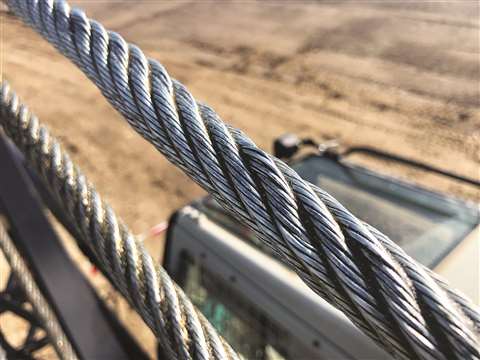
Hoisting loads with a wire rope is a simple operation. Hook it up; lift it. Turns out, it’s more complicated than it appears. The details of setting up, inspecting, and maintaining lifts with wire ropes are not complicated, but are critical. A lift that goes awry is dangerous. A bad lift puts workers at risk. In this article, we discuss the causes of wire rope failure and how to avoid them.
Abrasion breaks are caused by external factors such as coming into contact with improperly grooved sheaves and drums. Or just hitting against some object during operation. Worn, broken wire ends is the result of an abrasion break. Common causes of abrasion breaks include:
Core slippage or protrusion is caused by shock load or improper installation of the wire rope. Excessive torque can cause core slippage that forces the outer strands to shorten. The core will then protrude from the rope. Wire ropes designed to be rotation-resistant should be handled carefully so as not to disturb its lay length.
Corrosion breaks cause pitting on the individual wires that comprise the rope. This type of damage is caused by poor lubrication. However, corrosion breaks are also caused by the wire rope coming into contact with corrosive chemicals, such as acid.
There are many ways the strands of a rope can be crushed or flattened. Improper installation is a common cause. To avoid crushing, you’ll want the first layer of the wire rope to be very tight. You’ll also need to properly break-in a new wire rope. Other causes of crushing include cross winding, using a rope of the wrong diameter, or one that it too long.
Cracks to individual wires are caused by fatigue breaks. Fatigue breaks happen because the wire rope is being bent over the sheave over and over again. In time, the constant rubbing of the wire rope against the sheave or drum causes these breaks. Sheaves that are too small will accelerate fatigue breaks because they require more bending. Worn bearings and misaligned sheaves can also cause fatigue. A certain number of broken wires is acceptable. The worker responsible for equipment inspection prior to use should know the American Society of Mechanical Engineers (ASME) standard for wire ropes. The ASME standard determines whether the wire rope must be replaced. (https://www.asme.org/)
Selecting the right wire rope for the job is critical. There is never a perfect rope. For example, you will need to make a tradeoff between fatigue resistance and abrasion resistance. There are several aspects to wire rope design to consider, including:
In general, the proper wire rope will have a strength rating high enough to handle the load. (Strength is rated in tons.) It can handle the stress of repeated bending as it passes over sheaves or around drums. How you attach the rope in preparation for the lift matters and should only be handled by properly trained workers.
The wire rope (and all the equipment involved in a lift) should be fully inspected prior to the lift. The worker performing the inspection should be well-versed in the types of damage that can cause a wire rope to fail. Using a checklist is highly recommended. This will ensure that the inspection is complete. Worker and supervisor signoff will increase accountability. Of course, the wire rope must be maintained according to the manufacturer’s instructions.
How a wire rope is stored, the weather conditions in which it is used, and how they are cleaned all affect its useful life. The Occupational Safety and Health Administration (OSHA) provides these recommendations: (Source: https://www.osha.gov/dsg/guidance/slings/wire.html)
Preventing wire rope failures starts with selecting the right one for the job. When in doubt, talk with your local equipment dealer. Be prepared to discuss your specific job requirements. A thorough inspection of the wire rope prior to using it is critical. Finally, properly store your wire rope. The selection, inspection, and care of wire rope is key to job safety.
Workers involved in hoisting and rigging must exercise care when selecting and using slings. The selection of slings should be based upon the size and type of the load, and the environmental conditions of the workplace. Slings should be visually inspected before each use to ensure their effectiveness. Improper use of hoisting equipment, including slings, may result in overloading, excessive speed (e.g., taking up slack with a sudden jerk, shock loading), or sudden acceleration or deceleration of equipment.
Alloy steel chains are strong and able to adapt to the shape of the load. Care should be taken when using chain slings because sudden shocks will damage them. This may result in sling failure and possible injury to workers or damage to the load.
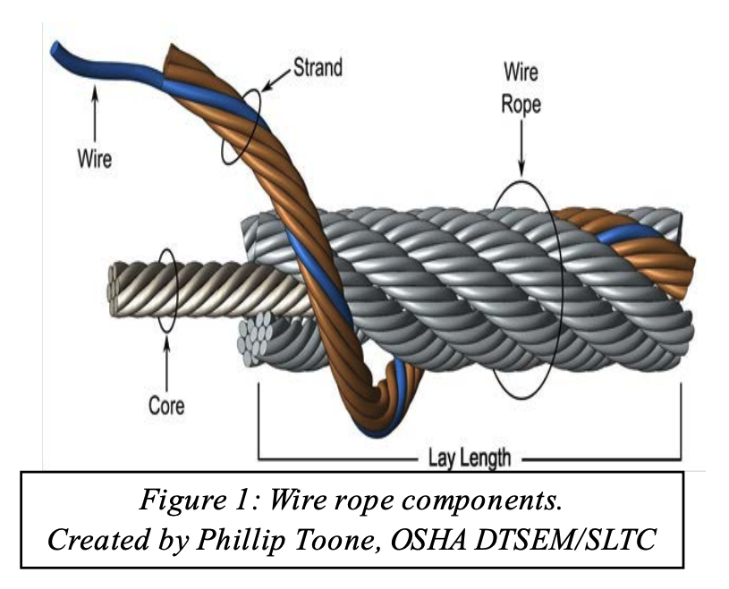
Wire rope is composed of individual wires that have been twisted to form strands. Strands are then twisted to form a wire rope. When wire rope has a fiber core, it is usually more flexible but less resistant to environmental damage. Conversely, wire rope with a core that is made of a wire rope strand tends to have greater strength and is more resistant to heat damage.
When selecting a wire rope sling to give the best service, there are four characteristics to consider: strength, ability to withstand fatigue (e.g., to bend without distortion), ability to withstand abrasive wear, and ability to withstand abuse.
Strength – Strength of wire rope is a function of its size (e.g., diameter of the rope), grade, and construction, and must be sufficient to accommodate the maximum applied load.
Fatigue (Bending without Failure) – Fatigue failure of wire rope is caused by the development of small cracks during small radius bends. The best means for preventing fatigue failure of wire rope slings is to use blocking or padding to increase the bend radius.
Abrasive Wear – The ability of wire rope to withstand abrasion is determined by the size and number of the individual wires used to make up the rope. Smaller wires bend more readily and offer greater flexibility, but are less able to withstand abrasion. Larger wires are less flexible, but withstand abrasion better.
Abuse – Misuse or abuse of wire rope slings will result in their failure long before any other factor. Abuse can lead to serious structural damage, resulting in kinks or bird caging. (In bird caging, the wire rope strands are forcibly untwisted and become spread outwards.) To prevent injuries to workers and prolong the life of the sling, strictly adhered to safe and proper use of wire rope slings.
Wire rope slings must be visually inspected before use. Slings with excessive broken wires, severe corrosion, localized wear, damage to end-fittings (e.g., hooks, rings, links, or collars), or damage to the rope structure (e.g., kinks, bird caging, distortion) must be removed from service and discarded.
Fiber rope and synthetic web slings are used primarily for temporary work, such as construction or painting, and are the best choice for use on expensive loads, highly finished or fragile parts, and delicate equipment.
Fiber rope slings deteriorate on contact with acids and caustics and, therefore, must not be used around these substances. Fiber rope slings that exhibit cuts, gouges, worn surface areas, brittle or discolored fibers, melting, or charring must be discarded. A buildup of powder-like sawdust on the inside of a fiber rope indicates excessive internal wear and that the sling is unsafe. Finally, if the rope fibers separate easily when scratched with a fingernail, it indicates that the sling has suffered some kind of chemical damage and should be discarded.
Shock Absorbency - Regardless of the construction material, shock loading (e.g., excessive speed, rapid acceleration or deceleration) of slings should be minimized. However, it should be noted that synthetic web slings can absorb heavy shocks without damage.


 8613371530291