
shock loading wire rope quotation

Shock loading can occur in any situation where the load on the crane suddenly increases. The crane and accessories are designed to take up the weight of loads gradually and steadily. They are not designed to withstand sudden increases or decreases in the apparent weight of the load. Some examples of how shock loading can occur are shown below.
Operators and equipment owners should be aware of the causes and potential dangers of shock loading. Because the equipment is being used in a way that it is not designed for, shock loading can lead to damaging the equipment, the facility, or injuring personnel. Understanding the causes of shock loading will help to prepare operators to safely and accurately operate the equipment.
Skilled operators are a company"s first defense against shock loading. Lifting and lowering should always be done in slow speed until all slack has been taken out of the wire rope and any below the hook devices. Additionally, operators should be aware of their surroundings, making sure that the load they are lifting is not likely to snag on other pieces of machinery or the building itself. When lifting or lowering the load, operators should be careful to make sure the load is not bouncing as they operate the hoist. Additionally, operators should ensure that their loads are secure and well balanced.
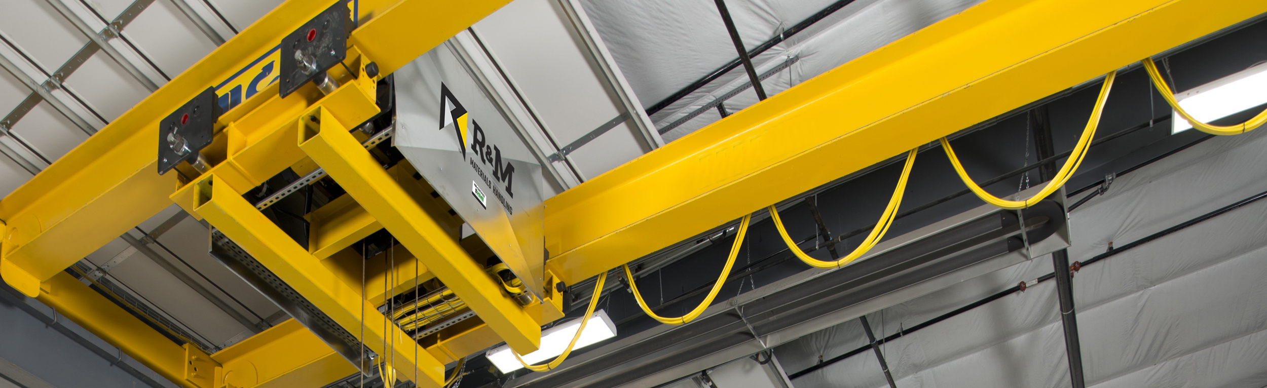
Beyond operator training and best practices, features such as the HoistMonitor®assist operators in preventing shock loads. The HoistMonitor ensures that starting and stopping is initiated in slow speed, which helps prevent a jumping motion of the load. Sudden load supervision, also a standard feature of the HoistMonitor, prevents the hoist from continuing the hoisting motion when a load increase is suddenly detected, like if the load snagged on another item.

When overloads and shock loads occur in a rigging operation, the results can be deadly. A failure of gear or equipment can take place at the time the over/shock load happens or in many cases weeks, months or years later.
Most of us are familiar with the statistics used in rigging books and charts on the effects of shock loading. When a load of “X” pounds is allowed to free-fall or is popped off the ground, it introduces a load to the lifting device which can be two times or more its static weight.
This compounding of weight takes its toll on the load’s internal and external structure, rigging attachment points, all rigging hardware, slings, hoist hook, running ropes, drum and entire hoisting system whether overhead or mobile crane.
A typical method of shock loading results from turning or flopping a load over from one plane to another. (Actual case) A coal-fired steam plant uses pulverizer journal assemblies to crush the coal into a fine talc – like powder for burning. The journals are awkward and difficult to handle with no available lifting lugs. After a journal is pulled from service and it has received maintenance, it is transported back to the pulverizer unit. A bridge crane picks up the journal from its vertical carrying cradle and sets the base on the floor. The crane then trolleys to pull or “flop” the journal over to a 45 degree angle. A special sling assembly is then used to hoist the journal into the pulverizer cavity.
During the “trolley and flop” movement, the slamming of the journal arms into their chain slings sends dust and dirt flying off the overhead bridge crane. How much weight in real pounds was introduced to the crane? Has anything happened to the crane’s structure? Does anyone suspect a broken weld, metal fatigue fracture or that damage has possibly occurred to the hoist system or wire rope? What if this happens twice a month for four years? Your imagination can provide many unwelcome answers to these questions.
Have you ever heard an employee say, “We were only lifting 2 tons on our 5 ton bridge crane and the whole thing came down on top of us!” Was it the 2 ton lift that caused the accident? Certainly not! It was the four years of repeated abuse, shock loading and structural damage which turned a fine bridge crane into a life threatening bucket of bolts.
If you have these situations in your operation, do everything possible to develop alternative rigging methods. Make a comprehensive inspection of all hoisting and rigging components. Using the proper procedures for each type of equipment perform load tests and make another inspection to ensure reliability. (Always check with the equipment manufacturer for testing procedures and limitations.)
MLA style: "Understanding shock loads.." The Free Library. 2013 United States Institute for Theatre Technology, Inc. 10 Dec. 2022 https://www.thefreelibrary.com/Understanding+shock+loads.-a0332379147
Chicago style: The Free Library. S.v. Understanding shock loads.." Retrieved Dec 10 2022 from https://www.thefreelibrary.com/Understanding+shock+loads.-a0332379147
APA style: Understanding shock loads.. (n.d.) >The Free Library. (2014). Retrieved Dec 10 2022 from https://www.thefreelibrary.com/Understanding+shock+loads.-a0332379147
Even with experienced crane operators, it can be challenging to lift a load without incurring stress to the crane, the load or the building’s structure. That’s because, before a load lifts off the ground, the rigging gear is loose and any upward hoisting would first move the rigging gear, not the load. Once the rigging gear is taut and the load is engaged, however, the hoist must be operated very slowly so as not to jerk the load into the air. Excess speed during the critical time of lifting the load off the ground can “shock” the crane system, causing high stress.
Konecranes has the answer: Shock Load Protection. With Shock Load Protection, the hoist drive monitors the load. If it is picked up too fast, the hoisting speed is automatically reduced until the load is in the air. This protects the crane, lifting load and the whole building from extra stress. This, in turn, provides lower maintenance costs for the crane and maximizes cycle times by reducing hoisting speed only during the critical moment of lift off.
Shock Load Protection is designed for smooth load pickups and works to prevent shocks to the load and the crane, extending the lifetime of the crane’s steel structure and mechanical parts. Shock Load Prevention is a feature of Konecranes Variable Frequency Drives for hoist control, and it works to eliminate shock loads automatically. With this automated feature, the operator can focus on controlling the load, monitoring his or her environment and ensuring that the load remains secure. Without the operator needing to purposely slow down operation as the hoist is raised, the crane can operate efficiently, speeding up operation while decreasing the mechanical wear and tear on the overhead crane.
Shock Load Protection is available for overhead cranes with, or with the capability of having, Variable Frequency Drives. Contact a Konecranes Representative to see if Shock Load Protection or any of our other Smart Features, can help your business.

The Working Load Limit is the maximum load which should ever be applied to the product, even when the product is new and when the load is uniformly applied – straight line pull only. Avoid side loading. All catalog ratings are based upon usual environmental conditions and consideration must be given to unusual conditions such as extreme high or low temperatures, chemical solutions or vapors, prolonged immersion in salt water, etc. Never exceed the Working Load Limit.
A load resulting from rapid change of movement, such as impacting, jerking or swinging of a static load. Sudden release of tension is another form of shock loading. Shock loads are generally significantly greater than static loads. Any shock loading must be considered when selecting the item for use in a system.

The load which a new wire rope may handle under given operating conditions and at an assumed design factor. A design factor of five is chosen most frequently for wire rope. (Operating loads not to exceed 20% of catalog breaking strength). Operating loads may have to be reduced when life, limb, or valuable property are at risk, or other than new wire rope is used. A design factor of 10 is usually chosen when wire rope is used to carry personnel. (Operating loads not to exceed 10% of catalog breaking strength). Responsibility for choosing a design factor with the user.
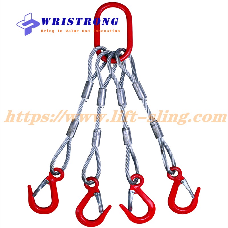
Rope sockets, thimbles, sleeves, hooks, links, shackles, sheaves, blocks, etc., must match in size, materials and strength, to provide adequate safety protection. Proper installation is crucial for maximum efficiency and safety.
LANDMANN WIRE ROPE PRODUCTS, INC. assumes no responsibility for the use or misapplication of any product sold by this firm. Responsibility for design and use decisions rests with the user. All products are sold with the express understanding that the purchaser is thoroughly familiar with the correct application and safe use of same. USE ALL PRODUCTS PROPERLY, IN A SAFE MANNER AND FOR THE APPLICATION WHICH THEY ARE INTENDED.
NEVER EXCEED THE WORKING LOAD LIMIT The Working Load limit is the maximum load which should ever be applied to a product, even when the product is new and when the load is uniformly applied -straight line pull only. AVOID SIDE LOADING. All catalog ratings are based upon usual environmental conditions, and consideration must be given to unusual conditions such as extreme high or low temperatures, chemical solutions or vapors, prolonged immersion in salt water, etc. Such conditions or high risk applications may necessitate reducing the Working Load limit. WORKING LOAD LIMIT WILL NOT APPLY IF PRODUCT HAS BEEN WELDED OR OTHERWISE MODIFIED. It should also be noted that it is the responsibility of the ultimate user to determine a Working Load limit for each application.
MATCHING OF COMPONENTS Components must match. Make certain that components such as hooks, links, or shackles, etc. used with wire rope (or chain or cordage) are of suitable material size and strength to provide adequate safety protection. Attachments must be properly installed and must have a Working Load Limit at least equal to the product with which they are used. Remember, chain is only as strong as its weakest link.
SHOCK LOADS Avoid impacting, jerking or swinging of load as the Working Load limit could be exceeded and the Working Load limit will not apply. A shock load is generally significantly greater than a static load. AVOID SHOCK LOADS.
REMEMBER: ANY PRODUCT WILL BREAK IF ABUSED, MISUSED, OVERUSED OR NOT MAINTAINED PROPERLY. Such breaks can cause loads to fall or swing out of control, possibly resulting in serious injury or death as well as major property damage.
WORKING LOAD LIMIT (WLL) The Working Load Limit is the maximum load which should ever be applied to the product, even when the product is new and when the load is uniformly applied -straight line pull only. AVOID SIDE LOADING. All catalog ratings are based upon usual environmental condition and consideration must be given to unusual conditions such as extreme high heat or low temperatures, chemical solutions or vapors, prolonged immersion in salt water, etc. NEVER EXCEED THE WORKING LOAD LIMIT.
SHOCK LOAD A load resulting from rapid change of movement, such as impacting, jerking, or swinging of a static load. Sudden release of tension is another form of shock loading. Shock loads are generally significantly greater than static loads. Any shock loading must be considered when selecting the item for use in a system. AVOID SHOCK LOADS AS THEY MAY EXCEED THE WORKING LOAD LIMIT.
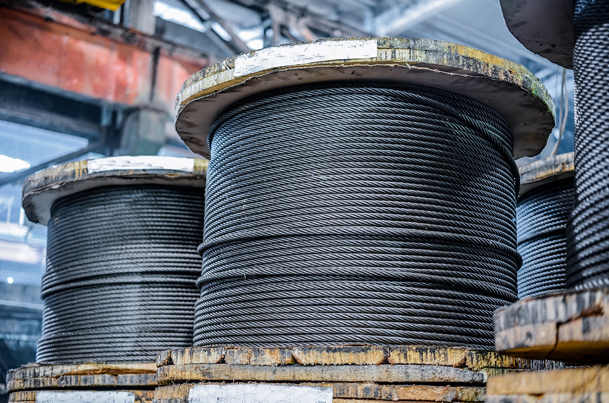
Our steel cable construction and wire rope assemblies offer a high strength to weight ratio, are long lasting, low maintenance, flexible and a cost efficient solution for many mechanical needs.
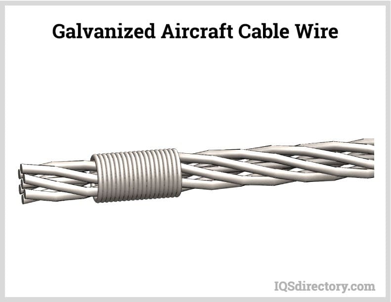
Commercial quality “aircraft grade” cable is made from galvanized steel wire or stainless steel wire. Galvanized aircraft cable provides high tensile strength and adequate corrosion resistance for most applications. Stainless steel wire cable provides slightly lower tensile strength, but greater resistance to corrosion.
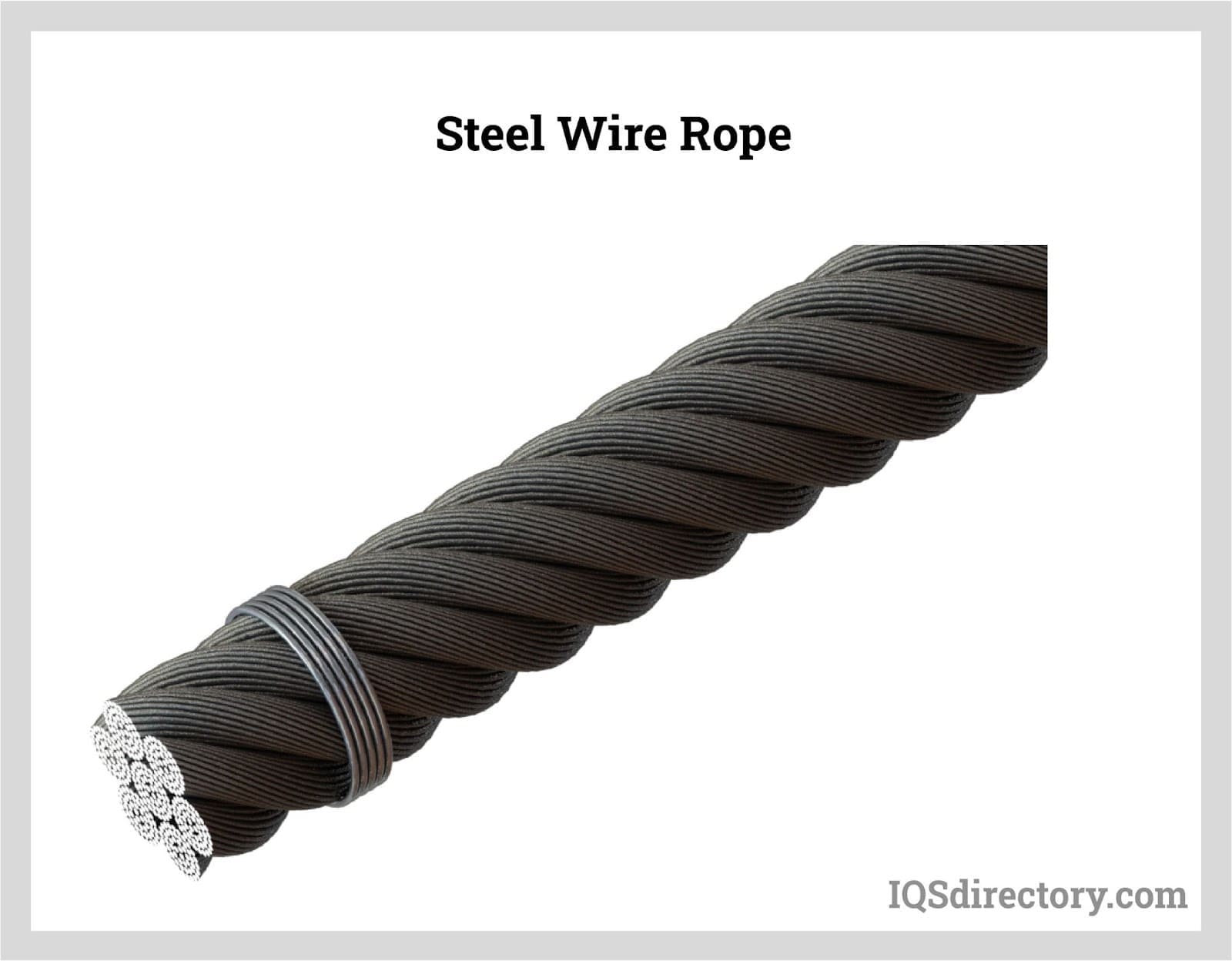
Industrial cable or wire rope is fabricated from individual wires put together in a uniform helical arrangement to form what is called a strand. A strand typically contains 7 wires (1x7) or 19 wires (1x19), although others are available. Cable or wire rope contains a varying number of these strands such as 7x7 and 7x19 (number of strands x wires per strand). The more strands and more wires per strand, the more flexible the cable and the higher the cost. The greater the cable diameter, the greater the diameter of each wire and the greater the breaking strength.
All steel wire cables can be coated with a number of different plastics such as vinyl (PVC) or nylon in various colors. Black, clear and white are typical stock colors but other colors can be ordered during the wire rope construction process.
The breaking strengths of various diameters of steel wire cable are listed here. Cable construction safety standards dictate a minimum of five to one safety factor when designing cables for most applications. If a cable is being designed for a 300 pound maximum weight load, then a 1/8 inch cable with a 1700 – 2000 pound breaking strength would be needed. For critical safety or shock load applications an 8 or 10 to one safety factor is needed. Request a quote on custom wire rope construction today and contact us with any questions about custom cable construction.
For more information or inquiries about our custom wire rope construction, get in touch with us today. Our team of experts are here to answer any of your questions. We look forward to hearing from you!

All products are sold with the understanding that the purchaser is familiar with their safe use and correct application. Fortune Rope & Metals Co., Inc. assumes no responsibility for the use or misapplication of any product it sells. Responsibility for design and use decisions rests with the user.
Never exceed the work load limit (WLL), safe working load (SWL), or rated capacity. The work load limit is the maximum load which should never be applied to the product, even when the product is new and when the load is uniformly applied — straight line pull only. Avoid side loading. All ratings are based upon usual environmental conditions, and consideration must be given to unusual conditions such as high or low temperatures, chemical solutions or vapors, prolonged immersion in salt water, etc. Such conditions, or high-risk applications may necessitate reducing the working load capacity. Work load limit will not apply if product has been welded or otherwise modified.
Components must match. Make certain that components such as hooks, links, shackles, etc., used with wire rope (or chain or cordage), are of suitable material and strength to provide adequate safety protection. Attachments must be properly installed and must have a work load limit at least equal to the products with which they are used. Remember — any chain is only as strong as its weakest link.
Avoid impacting, jerking, or swinging of a load — Work Load Limit will not apply. A shock load is generally significantly greater than the static load. Avoid shock loads.
Frequency of inspection will depend on environmental conditions, application, storage of object prior to use, frequency of use, whether or not life, limb, or valuable property are at risk, etc. When in doubt inspect products prior to each use. Carefully check each item for wear, deformation, cracks or elongation — a sure sign of imminent failure. Immediately withdraw such items from service.
AVERAGE TENSILE STRENGTHS shown are for new (unused) rope and will decrease after use. All tests were performed in accordance with ASTM test method 4268-83.
The rope strength will be reduced after use due to heat, abrasion, ultraviolet, or chemical exposure. The tensile strengths may be further reduced by up to 50% as a result of knots or kinks.
MAXIMUM WORKING LOADSare determined by dividing the average tensile strength by the safety factor. The safety factor is a function of the physical properties of the rope, the age and history of the rope, the type of service it will be subjected to, and the risks involved if a failure occurs. For a rope manufacturer to give blanket working load recommendations would be like a car manufacturer giving the “safe driving speed” of their cars.
Obviously the conditions of use far outweigh the design characteristics of the rope. Typically safety factors vary from 3:1 (for the new rope used in applications with uniform loading and where failure would cause little or no risk to equipment or personnel) to 20:1 (for conditions involving moderate shock loading, the possibility of snags or kinks or where failure could cause severe risk to equipment or personnel).
ROPE TERMINATIONSDCL can provide custom terminations such as thimbles, links, rings, and custom hardware. Terminations are available in plastic, bronze, stainless steel, and galvanized steel. Please call, email or fax your requirements for a quotation.
SPECIAL COATINGS such as polyurethane, polyethylene, and vinylesters may be applied to any of the synthetic ropes to improve the snag resistance, sunlight resistance, or for color-coding. DCL can provide ropes with a variety of finishes to meet your needs.
Shock loads are hard to prevent during loading and unloading of sea going vessels. Therefore the influence of this kind of overload on the endurance of steel wire ropes on harbour cranes, which are supposed to have resistance to these impact forces, are of interest in a country with large harbours like Rotterdam. The capability of a rope to absorb the amount of energy coupled with shocks, depends largely on the total stiffness of the whole system and its rope. This makes the research of this item with data from practical applications almost impossible.

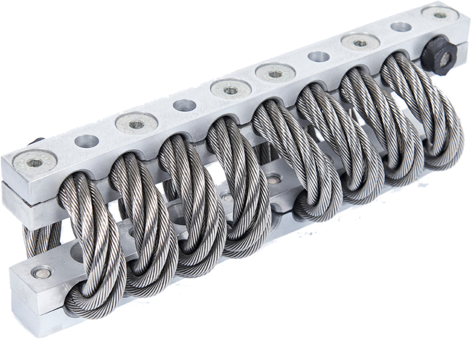
The CA Series Circular Arch Wire Rope Isolators are made of captive, flexible wire rope elements with upper and lower attachment plates. The stranded-wire rope elements provide a high degree of damping with measurable predictable shock and vibration isolation performance. Designed to protect sensitive equipment in severe environments, the CA Series are ideal for isolating panel boards, wall mounted computers and accessories, medical equipment, closed-circuit television and other wall mounted equipment.
The CA Series Circular Arch Wire Rope Isolators consist of stainless steel, standard wire ropes. Wire ropes on CA models are connected to zinc-plated, low carbon steel mounting discs. The isolators offer three-plane, all-axis isolation that permits use in any attitude – vertically, horizontally and lateral. The isolators offer excellent shock attenuation with low frequency, high vibration isolation damping in a failsafe design. Standard spaced washers prevent the isolator coils from moving upward, under load, above the plane of the upper mounting disc – an effect know as heart-shaping.
Polyester is considered by some to be the best general purpose rope. It"s also one of the more popular choices when a tough heavy duty rope is needed.
Polyester rope is a great rope for general industrial applications as well as rigging applications. It does great in the outdoors and tough elements of nature. Can be seen being used for lines to tie down or hold back boats in marine applications.
A few uses for this rope may include: winches, dock rigging, blocking, or simple household applications. It can also be mistaken many times as Nylon with many fine details in differences. Largest difference being it"s resistance to chemicals.
A very quick knot to tie, the square knot is used to join two ropes together in a simple and effective way. However, you should be aware that this knot is not reliable for heavy weights or critical situations. The square knot has been used for centuries to join two ends together for bandages or shoelaces or belts. The Boy Scouts require skill with this knot for general purposes.
The bowline was originally used in a marine setting (as are many knots), but has proved itself useful in a wide range of situations. The qualities of this knot are its simplicity, strength and resistance to jamming. Because of the intentionally open loop in the completed knot, the bowline can be slung over a post or other object after it has been tied. This knot can also be tied after the rope has been passed through a ring. You should be cautious as the knot can become undone if it is shaken or jostled.
A simple knot with the most basic tying steps. Used mainly as a stopper in such applications like climbing ropes or to stop the rope from falling out of a pulley system.
The Sheet bend is best used to join two ropes of unequal sizes. This is great for broken splices or just needing a few extra feet to pull down that branch.
These are some of the more common knots used for work or play. An emergency situation is not the time to try to tie one of these knots. It is best to be prepared by practicing these knots before you need them. Many knot tying guides are available. Find one with good illustrations and practice with inexpensive rope or scraps. You will then have the confidence to take full advantage of rope and the many situations you are likely to encounter.

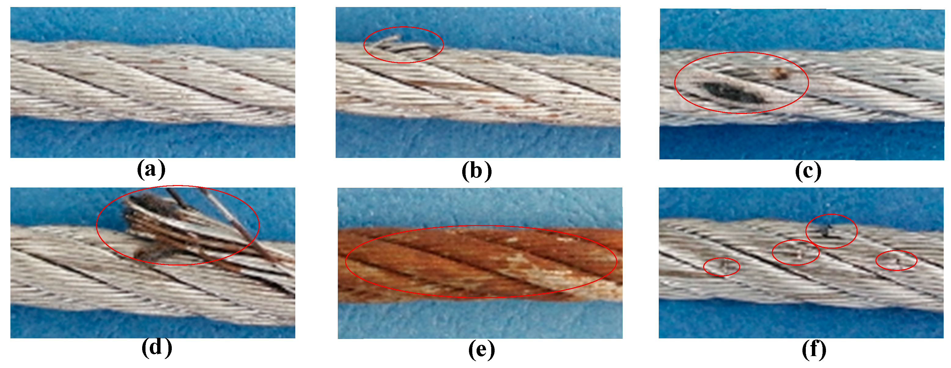
As the key bearing components in engineering projects, wire ropes often suffer from high-speed impact loads in service. In the majority of applications, wire ropes are subjected to the loads with the following characteristics: alternating impact loads, short-time overload, and small movements among adjacent spiral strands. Typical failure modes of wire ropes include fracture, wear, corrosion, geometric failure and thermal failure. In this work, the corresponding failure mechanisms were analyzed. For a certain type of wire ropes, the fracture morphology, surface quality, microstructure and internal defects of steel wires were analyzed, and failure causes were discussed. Accordingly, the precautions in relation to the safe use of wire ropes were proposed.


 8613371530291