
spacemaster sx wire rope hoist factory
We are committed to helping you rise above the challenges of your everyday business. The safety, reliability and reduced maintenance of the Spacemaster® SX wire rope hoist allows you to get the most out of your equipment. As a standard feature, this hoist includes hoist monitoring to provide real-time data about hoist operation.
Designed to maximize dimensional envelope and operational efficiency, the wide capacity range of this hoist is ideal for applications across industries. The Spacemaster SX wire rope hoist can be configured to your precise facility needs, from building headroom and workflow needs to environmental considerations.
Our innovative hoist design provides the best headroom in the industry while minimizing hook drift and maximizing end approaches. This means you get more floor coverage and easier operation of the equipment. Standard inverter controls on the trolley reduce load swing and minimize brake wear.
R&M offers load monitoring systems as standard with every wire rope hoist. The HoistMonitor and HoistWatch systems give you real information about your equipment use and service needs while preventing overloads to the crane. In addition, our regenerative braking system can ensure safe operation for your crane operators.
At R&M, all our equipment is designed in-house, specifically for lifting applications. The innovative gear case design reduces stress on drum bearings, lowering the need for maintenance and extending the life of the equipment. Our unique rope drum design, with 40:1 drum to rope diameter and motor inside the drum, provides the least hook drift in the industry while improving motor cooling efficiency.
Our RX Program has a selection of wire rope hoists ranging from 1 to 40 tons, available in 2-5 business days! Ask a R&M Distributor for more information on this program.
Have an upcoming project? Use our Crane Designer for an instant recommendation of crane and hoist components that will help you rise above your competition.
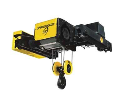
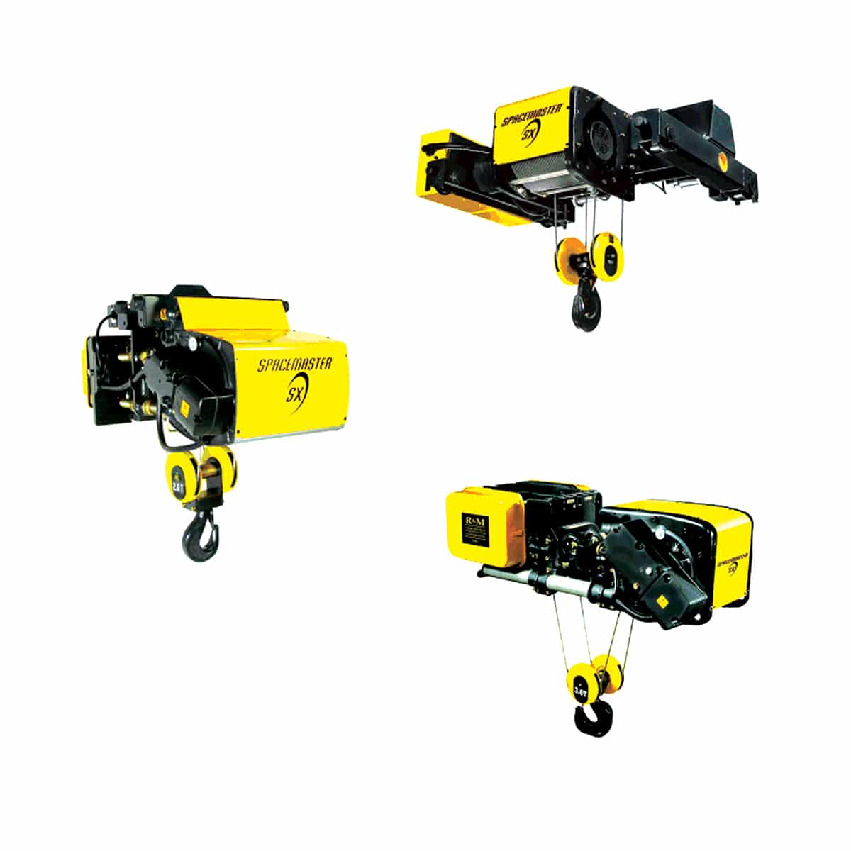
The R&M Spacemaster® SX design utilizes a large drum diameter ensure the lowest headrooms and best wheel loads in the industry. The single reeved hoist provides near true vertical lift with only 1/8" of drift per foot of lift making load positioning accurate and easy. The reduce trolley frame allows exceptional hook approaches. The SX features low maintenance, sealed brakes, a two-speed hoist motor, and trolley inverter control.
Hoist and trolley motors: The standard hoist is two-speed with a 6:1 ratio. The motors are designed specifically for hoisting applications, offers high starting torque and ensures precise and reliable load handling. This motor is class F insulated. It is rated for use 30 minute out of an hour giving it a 60% effective duty. The trolley motor"s standard VFD control offers two-step or infinitely variable control for smooth acceleration and deceleration, minimal load swing; fast, and precise load placement.
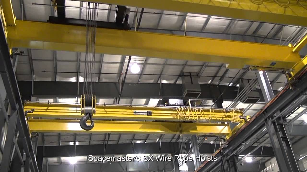
The Spacemaster® SX Electric Wire Rope Hoists from R&M Materials Handling represents a revolutionary new generation of exceptionally reliable electric wire rope hoists, featuring advanced technology and cutting-edge performance.
An innovative design that includes a large drum diameter gives Spacemaster® SX hoists the lowest headrooms and best wheel loads in the industry while providing near true vertical lift with single reeved hoists, and both exceptional hook approaches and heights of lift.
Standard electric wire rope hoist configurations include normal headroom, low headroom and double girder trolley designs. Hoists in short ton ratings (ASME) or metric ratings (FEM) meet a wide variety of application requirements:

The Spacemaster® SXs’ unique hoist features include new low maintenance, sealed brakes, a two-speed hoist motor, and trolley inverter control. The standard hoist nameplate will carry a CSA c/us rating as well as a NEMA 3R rating for electrical enclosures. Two-component epoxy paint is standard. Spacemaster® SX hoists are designed to meet and exceed either …
The Spacemaster® EX electric wire rope hoist is the hazardous location version of the industry leading Spacemaster® SX hoist. An innovative design that includes a large drum diameter gives the Spacemaster® EX hoists the lowest headrooms and best wheel loads in the industry, while providing near true vertical lift with single reeving, as well as exceptional hook approaches …
The CM Series 653 Lever Operated Hoist features a short handle and minimal lever pull effort combined with high quality, rugged steel for close quarter pulling, stretching, and hoisting applications. This lever hoist is ideal for a wide array of applications in construction, industrial and plant operations.
JET® S90 Series hand chain hoists were designed with reliability and durability to perform in light-duty industrial applications. Easily maintained and serviced, the JET® S90 is available in capacities from ½ ton to 10 ton and standard lifts of 10, 15, 20, and 30 feet (custom lifts available). The JET® S90 is the ideal contractor …
JET is committed to delivering the simplest and most efficient safety solutions. The JLP-A series lever hoists are designed to create a safer work environment. The JLP-A comes standard with the new brake wear indicator. This technology adds additional safety to the job by providing a visual indication when the brake discs need replacing. JLP-A …
Harrington’s Harringtons TCS CHEETAH air chain hoist is available in 1/4, 1/2 and 1 Ton capacities with either pendant or cord control. This hoist has extremely fast and uniquely adjustable lifting and lowering speeds. The TCS is lightweight, compact and has outstanding feathering ability making it a perfect fit for fast-paced assembly line and workstation …
Harrington’s TCR large capacity air chain hoists are market tested and proven to be durable and easily repairable. These high-performance hoists have all of the power required for lifting very heavy material and are the ideal choice for extreme applications including in mines, shipyards, heavy construction, rigging situations and the petrochemical industry.
Harrington’s TCR air chain hoists are designed with a heavy-duty standard body and are able to lift heavy loads in the most demanding or harsh environments. Available in cord control which allows operator to remain within reach of the load and pendant control that provides easier inching or feathering and permits operation from a remote …
Harrington’s SNER electric chain hoists are built for extreme duty applications that require single phase power. A hoist with a 60 minute, H4 duty rated motor is revolutionary and unmatched in a single phase offering. Maintenance friendly features include a unique chain guide, hinged control panel, sealed housing and durable load sheave. For beam travel …
Harrington’s unique SEQ model hoist is a DUAL SPEED VFD, 1-PHASE electric chain hoist with re-connectable 115/230V power. This hoist also includes a no-load high speed function that automatically increases hoist speed up to 130 percent when the load is less than 30 percent of working load limit. Mount the SEQ hoist to our PT …
Harrington’s LB lever hoists combine easy operation with a compact, low headroom design that easily handles real-world demands. Rated the number 1 selling lever hoist in the U.S., these hoists can be used horizontally, vertically, inverted or at any other load angle and have the strength to get the job done.
Harrington’s EQ dual speed VFD 3-phase electric chain hoists are designed for medium to heavy-duty industrial and workstation applications. These hoists include a unique no-load high speed function that automatically increase hoist speed up to 130% when the load is less than 30% of working load limit. Add our MRQ motorized, PT push and GT …
Harrington’s AH Mini Cat air chain hoists offer an extremely lightweight, small body design suitable for on-site jobs, workstations and assembly line applications. Available in pendant, cord and manipulator control and all models can easily lug mount to our ET mini trolley for added mobility. This hoist weighs only 12 lbs. with 10 foot of …
Harrington’s MR three-phase motorized, PT manual push and GT manual geared trolleys easily couple with our (N)ER enhanced features electric chain hoists and provide excellent traversing motion and control. MR electric trolleys are built for the most demanding applications while our PT and GT manual trolleys are used for traversing a load when electric power …
Harrington’s (N)ER enhanced features three phase electric chain hoists are equipped with the latest technology in the market today. All models include a low headroom, lightweight body with a fan-cooled motor, standard thermal motor protection and a count hour meter for preventive maintenance. A secondary mechanical load brake is an additional features on ER models …
JET L-100 Series hand chain hoist integrates safety, durability and innovation enabling it to operate in the most demanding industrial environments. The patented fused brake system reduces maintenance costs and limits downtime. The JET® L-100 is available in ¼ ton to 20 ton capacities and standard lifts of 10, 15, 20, and 30 feet (custom …
Harrington’s SHB trolley hoists combine our industrial grade CB hand chain hoist less slip clutch with a unique permanently attached hand geared trolley. This low profile configuration is ideal for use in limited space applications.
Harrington’s CB and CF hand chain hoists can easily be coupled with our PT push trolleys and our GT geared trolleys for added mobility. These trolley/hoist combinations offer all of the top quality features and benefits of the individual hoist and trolley.
Harrington’s CF hand chain hoists were designed for portability and durability. These hoists are the economical and practical choice for efficient, trouble-free service. The CF model is a long-lasting construction grade hoist that offers the best value in a hand chain hoist.
The CM Cyclone Hand Chain Hoist features superior engineering, efficiency, and durability and is considered one of the most popular hand chain hoists ever designed. It is available in a variety of capabilities from ¼ ton to 10 tons.
The CM Valustar Electric Chain Hoist features a compact, lightweight design built specifically for general commercial applications. Valustar is an economical choice for your material handling needs.
The CM ShopAir Chain Hoist features superior lifting speeds, rugged design, and precise load spotting in a portable air chain hoist. It is ideal for a workstation hoist or a production line hoist due to its compact design and very light weight.
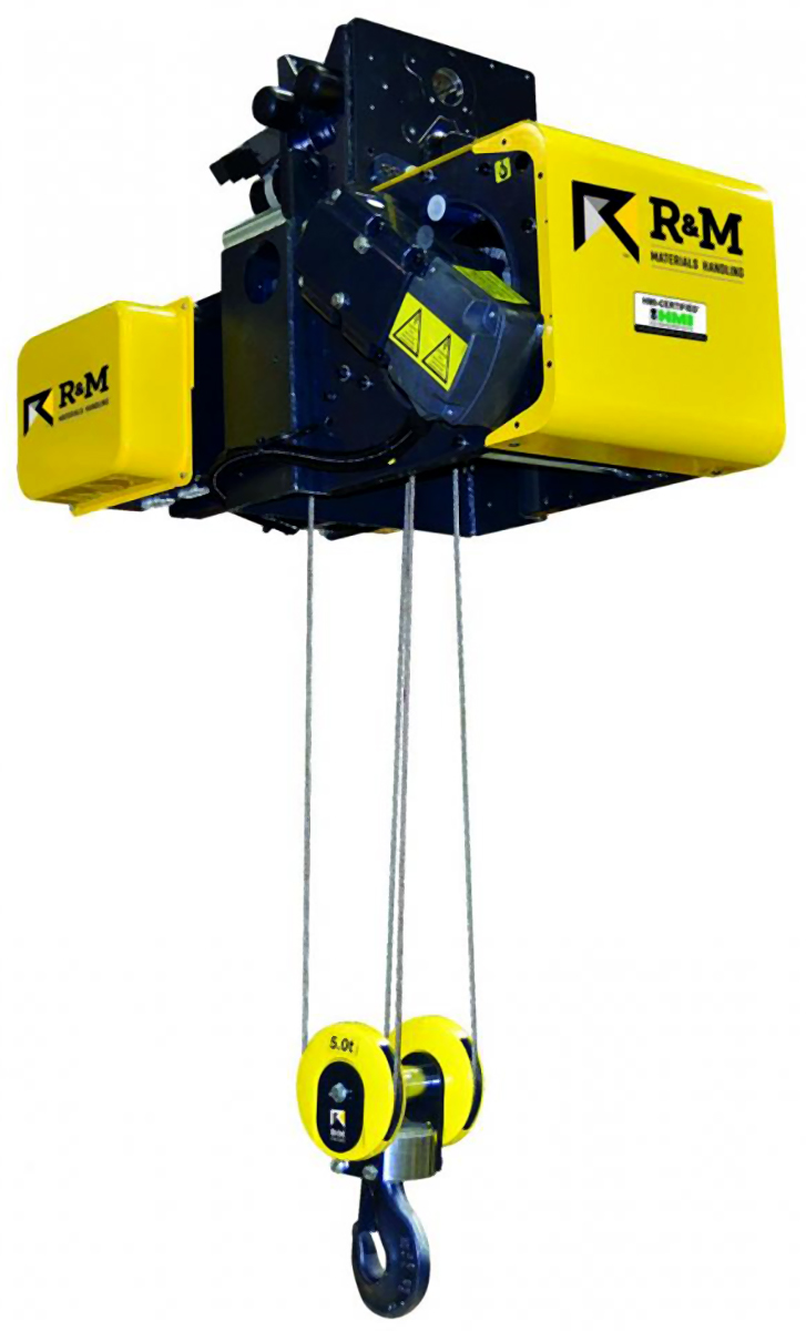
Large-diameter hoist drum means easy positioning, closer approaches. The larger drum diameter provides near true vertical lift with a single-reeved hoist—only 1/8″ drift per foot of lift. The result is exceptionally smooth movement and fast load positioning. This innovative design also means a shorter frame length, allowing closer end approaches. Hoist and trolley motors designed for space savings and productivity. Standard two-speed hoist motor (6:1 ratio), designed specifically for hoisting applications, offers high-starting torque and ensures precise and reliable load handling.
Standard safety features that competitors don’t offer—or offer at extra cost. An electromechanical load limit switch prevents the lifting of loads that are in excess of 110% of rated capacity. The 4-position hoist limit switch includes an innovative phase mismatch protection circuit that prevents the block from running up and damaging the hoist in the event of phase reversal.
Sealed brakes, hardened ground gears, thermal motor protection, exceptional rope life and ergonomic hook block design with sturdy safety latch contribute to the hoist’s safe operation and increased reliability.
Sealed brakes mean long-term value. Sealed dust-proof brakes on the trolley and hoist motors require little adjustment for over a million cycles, and will last the life of the hoist under normal use.
Trolley design reduces wear on components. The trolley drive is totally enclosed, grease lubricated and designed to be maintenance-free. Trolley wheel bearings are permanently lubricated. The automatic disc brake and inverter control help extend the life of the motor and other components, which means less maintenance, less downtime, lower repair costs—and reduced cost over the lifetime of your hoist equipment.
Innovative gearbox provides dependable operation and extends equipment life. The innovative gear case design reduces stress on drum bearings, reducing the need for maintenance, while extending component life. It features hardened and ground internal reduction gears driving an external drum gear located on the inner surface of the rope drum. The gearbox’s semi-fluid grease lubrication also helps to extend its working life. The gear case is designed to run cooler and more efficiently than those equipped with a mechanical load brake.
Larger hoist drum minimizes rope wear and enhances cooling. A drum / rope diameter ratio of approximately 40:1 minimizes rope flex, reducing wear and extending rope life. The drum’s large diameter also contributes to a reduction in frame size and weight, reducing wear on hoist components and enabling the use of more cost-effective crane girders. The unique placement of the hoist motor inside the drum provides directed airflow through the drum for optimal motor cooling. This design also makes the motor and brake more easily accessible.
2.1 FEM Hoist Duty Service Classification ............................................................................................................... 7
2.2 ASME Hoist Duty Service Classification............................................................................................................. 8
4.2 Hoist Speed Accuracy ...................................................................................................................................... 10
4.5 Rope Type Code .............................................................................................................................................. 10
4.6 Hoist Duty Rating ............................................................................................................................................. 10
6.1 Hoist Motor Features ........................................................................................................................................ 31
6.2 Optional Hoist Motor Features ......................................................................................................................... 31
6.10 Hoist Motor Brake ............................................................................................................................................ 32
7.1 Hoist Gear Reducer ......................................................................................................................................... 52
7.2 Hoist Gear Lubricant ........................................................................................................................................ 52
8.3 Rope Clamps ................................................................................................................................................... 54
8.4 Rope Guide ...................................................................................................................................................... 54
9.4 Rope Anchor .................................................................................................................................................... 57
10.1 Wire Rope Technical Data ............................................................................................................................... 58
10.2 Heavy Duty Wire Rope – RR09 ........................................................................................................................ 59
12.1 SX2-SX7 Hoists ............................................................................................................................................... 65
14.1 Low Headroom Hoist ........................................................................................................................................ 67
14.2 Normal Headroom Hoist ................................................................................................................................... 68
14.7 Cross Mounting Double Girder Hoist ................................................................................................................ 70
22.1 Monorail Hoist (Solo Hoist) ............................................................................................................................... 88
22.2 Crane Package Hoist ....................................................................................................................................... 88
25.1 HoistMonitor ® – HS11 ...................................................................................................................................... 90
25.4 HoistMonitor ® Select – HS12 ........................................................................................................................... 91
25.5 HoistMonitor ® Elite – HS13 .............................................................................................................................. 92
27.1 Hoist & Trolley Color Layout ............................................................................................................................. 95
27.3 Standard Painting Method for Hoist ................................................................................................................. 96
27.4 Special Painting Specification for Hoist ............................................................................................................ 96
29.1 Second Hoist Brake – BRA01 ........................................................................................................................ 100
29.11 Special Encoder on Hoist – EL20 ................................................................................................................... 101
29.12 Hoist Inverter Control Method – EL36 ............................................................................................................ 101
29.13 Hoist without Electrical Controls – ELE65 ...................................................................................................... 101
29.16 Hoist Motor, IP66 Protection – HM04 ............................................................................................................. 101
29.17 Hoist Motor, Thermal Protection – HM05 ....................................................................................................... 101
29.18 Hoist Motor, Class H Insulation – HM12......................................................................................................... 102
29.19 Speed Sensor on Hoist Motor – HM13 ........................................................................................................... 102
29.22 Rain/Dust Cover for Hoist – HS04 .................................................................................................................. 102
29.23 Hoist Drum Brake – HS07 .............................................................................................................................. 102
29.27 Synchro for Hoisting – HS27 .......................................................................................................................... 103
29.37 Nonstandard Voltage/frequency for Hoist....................................................................................................... 106
29.39 Hoist Motor External Fan – MOT08 ................................................................................................................ 107
29.45 IP-type of Hoist Panel (Add for IP66) – PAN01 .............................................................................................. 107
29.47 Stainless Steel Hoist Panel (IP55) – PAN03 .................................................................................................. 107
29.52 Stainless Wire Rope – RR08 .......................................................................................................................... 108
29.53 Heavy Duty Wire Rope – RR09 ...................................................................................................................... 108
33.4 Hoist Speeds and Controls ............................................................................................................................. 112
33.7 Two Similar Hoists Arrangement .................................................................................................................... 113
39.17 Pliotex Type Wire Marking – ELE48 ............................................................................................................... 118
Also known as spark resistant, these hoists are used in applications where there is the possibility of a spark igniting a gas that could result in an explosion.
R&M"s Spacemaster SX wire rope hoist features a large drum diameter that creates near true vertical lift, and its frame design allows closer end approaches than other hoists on the market. Standard electric wire rope hoist configurations include normal headroom, low headroom and double girder designs.
The Spacemaster® EX Class I, Division 2 Hoist is an industry-leading, explosion-proof hoist for maximum safety in potentially combustible environments.
Used in light usage applications or where precise positioning is necessary. Manual chain hoists can be used in similar applications as electric chain hoists.
RMII manual chain hoists are available as standard with a 10-foot lift, or with any custom lift height up to 98 feet. The standard top hook design can be paired with one of R&M"s manual trolley options, or opt for an integral hand geared chain trolley or manual push trolley (1/2 - 5 ton [500 - 5000 kg] capacities), which lowers the overall headroom of the hand chain hoist and trolley.
R&M"s innovative LK electric chain hoist is offered in capacities from 1/8 - 5 ton (125 -5000 kg). With the drive train originally designed to meet the noise and size specifications of the entertainment market, you will not find a quieter or more compact design in the industry. The LK electric chain hoist comes standard with all the features you need to get up and running today.

1 UPDATE HISTORY ............................................................................................................................ 42 GENERAL INTRODUCTION .............................................................................................................. 5 2.1 Foreword: About this manual............................................................................................................5 2.2 Symbols used in this manual ............................................................................................................5 2.3 Safety Alert Symbols and Signal Words ...........................................................................................5 2.4 Questions and Comments ................................................................................................................6 2.5 Manual Use.......................................................................................................................................6 2.6 Service personnel .............................................................................................................................6 2.7 Terminology ......................................................................................................................................7 2.8 Standards and Directives .................................................................................................................73 SAFETY FIRST! ................................................................................................................................. 8 3.1 Personal protective equipment (PPE) ..............................................................................................8 3.1.1 Fall Protection ...................................................................................................................................8 3.2 Fire Safety ........................................................................................................................................9 3.3 Main isolation switch .........................................................................................................................9 3.4 Safety during maintenance ...............................................................................................................9 3.4.1 Lockout - Tagout Procedure ...........................................................................................................114 IDENTIFICATION............................................................................................................................. 12 4.1 Manufacturer ...................................................................................................................................12 4.2 Hoist series .....................................................................................................................................13 4.3 Hoist Identification Data ..................................................................................................................14 4.4 R&M code example (R&M: SX, Factory: Q) ...................................................................................15 4.5 Motor Identification Data .................................................................................................................165 GENERAL ABOUT MAINTENANCE ................................................................................................ 18 5.1 Service process ..............................................................................................................................18 5.2 Periodic inspections and actions ....................................................................................................19 5.2.1 Daily inspections .............................................................................................................................19 5.2.2 Periodic inspections and maintenance tasks .................................................................................19 5.3 Approaching Theoretical Calculated Lifetime .................................................................................21 5.3.1 General Overhaul ...........................................................................................................................216 MAINTENANCE PROGRAM ............................................................................................................ 23 6.1 Periodic inspections and maintenance tasks .................................................................................23 6.2 Lubrication ......................................................................................................................................34 6.2.1 General Lubrication Instructions .....................................................................................................34 6.2.2 Lubrication Charts (Low headroom trolley) ....................................................................................36 6.2.3 Lubrication Charts (Normal headroom trolley) ...............................................................................37 6.2.4 Lubrication Charts (Double girder trolley) .......................................................................................38 6.2.5 Lubrication Charts (Fixed hoist) ......................................................................................................39 6.2.6 Lubrication Charts (Machinery Hoist) .............................................................................................40 6.2.7 Lubricant volumes, hoisting gears ..................................................................................................44 6.2.8 Lubricant volumes, drum rim gear ..................................................................................................44 6.2.9 Lubricant volumes, traveling gears .................................................................................................447 MAINTENANCE INSTRUCTIONS.................................................................................................... 45 7.1 Hoisting machinery .........................................................................................................................45 7.1.1 Hoisting machinery .........................................................................................................................45 7.1.2 Rope drum ......................................................................................................................................53 7.1.3 Rope clamps ...................................................................................................................................56 7.1.4 Rope guide .....................................................................................................................................58
7.1.5 Hoisting gearbox ............................................................................................................................. 82 7.1.6 Hoisting motor ................................................................................................................................ 88 7.1.7 Hoisting brake................................................................................................................................. 93 7.1.8 Second brake, Frame size: SX1, SX2, SX3, SX4, SX5. ................................................................ 98 7.1.9 Drum Brake .................................................................................................................................. 100 7.1.10 Manual brake release for hoisting motor ...................................................................................... 119 7.1.11 Manual crank ................................................................................................................................ 122 7.1.12 Hoisting limit switch ...................................................................................................................... 125 7.1.13 Hook operated limit switch ........................................................................................................... 134 7.2 Rope reeving system .................................................................................................................... 141 7.2.1 Standard reevings (one rope from drum) ..................................................................................... 141 7.2.2 True vertical reevings (two ropes from drum)............................................................................... 145 7.2.3 Machinery reevings ...................................................................................................................... 148 7.2.4 Rope sheave maintenance ........................................................................................................... 150 7.2.5 Sheave support and rope anchorage support .............................................................................. 151 7.2.6 Wire rope ...................................................................................................................................... 152 7.2.7 Hook-block .................................................................................................................................... 160 7.2.8 Overload protection ...................................................................................................................... 175 7.2.9 Rope anchorage ........................................................................................................................... 180 7.3 Trolley ........................................................................................................................................... 185 7.3.1 Trolley ........................................................................................................................................... 185 7.3.2 Trolley buffers ............................................................................................................................... 187 7.3.3 Traveling machinery ..................................................................................................................... 188 7.3.4 Traveling motor ............................................................................................................................. 191 7.3.5 Traveling brake ............................................................................................................................. 195 7.3.6 Trolley wheels ............................................................................................................................... 201 7.4 Electrics ........................................................................................................................................ 210 7.4.1 Push-button controller .................................................................................................................. 210 7.4.2 Condition monitoring unit .............................................................................................................. 211 7.4.3 Frequency converters ................................................................................................................... 212 7.4.4 Cubicles and wiring ...................................................................................................................... 215 7.4.5 Contactors .................................................................................................................................... 2158 DISMANTLING .............................................................................................................................. 216 8.1 Dismantling the Product ............................................................................................................... 216 8.2 Disposal of Waste Material ........................................................................................................... 2179 APPENDIX: TIGHTENING TORQUES .......................................................................................... 218
2.1 Foreword: About this manualThis manual offers guidance to enable safe and efficient service.Taking the time to read this manual will help you to prevent damage to the product, and, most importantly,personnel situated close to it. The product is designed to be safe when used correctly. However, there are manypotential hazards associated with incorrect operation and these can be avoided when you know how to recognizeand anticipate them.This manual is not intended as a substitute for proper training but provides recommendations and methods for safeand efficient service.
2.4 Questions and CommentsAny questions or comments relating to the content of this manual and/or the operation, maintenance and/or serviceof manufacturer products should be directed to: www.rmhoist.com
ANSI American National Standards InstituteISO International Organization for StandardizationAuthorized personnel Persons who are authorized by the owner and who have the necessary training to carry out operation or service actions.Experienced service person authorized by A person with service experience who is properly trained to perform service actions.the manufacturerCE marking The CE-marking indicates that the product complies with the appropriate CE regulations.Check A visual and functional assessment (not a test) of the product without dismantling.Emergency brake A brake that can be applied by the operator, or automatically upon loss of power.Electric panel Power is controlled to the motors and components through the electric panel.Parking brake (storm lock) A brake that can be applied either automatically or manually and prevents horizontal movement of the trolley or bridge. Used when movements need to be prevented in windy conditions.Main brake A brake that stops motion and prevents movements.Second brake (Holding brake) A brake that supports the load if the main brake fails.Operator Person operating the product for the purpose of handling or moving loads.Inching Making very small movements by repeatedly and momentarily pressing the direction control.Bridge The bridge (main girder) moves along the runwayMain girder The main girder (bridge) is connected to the bridge end carriages.Main isolation switch The main isolation switch is the power switch which the operator should normally use to turn off the power.Hoist Drive mechanism for lifting and lowering the load.Inspection (Visual) Looking for defects and checking the operation of the controls, limiting and indicating devices without loading the product. This is much more than a check but does not normally require any part of the product to be dismantled other than for removal or opening of covers or housings.Power supply Power is supplied to the components via the power supply.Controller The pendant or other type of controller is used by the operator to give commands to the product.Qualified personnel One with necessary qualification based on theoretical and practical knowledge of hoists or/and cranes. The person must be in a position to assess the safety of the installation in conjunction with the application. Persons with the authority to undertake certain maintenance work on products of manufacturers include manufacturers’ service engineers and trained fitters with corresponding certification.Maximum capacity Load that the product is designed to lift for a given operating condition (e.g. configuration, position of the load).Runway The product rides on or under the runway.Trolley (hoisting unit) The trolley (hoisting unit) moves along the main girder.Sling A sling is used to attach the hook to the load when the load cannot be lifted directly by the hook.
2.8 Standards and DirectivesThis state of the art product has been designed and manufactured to conform to European and internationalstandards and directives. The product also fulfils the requirements of the following standards (if applicable): CSA,UL, RoHS, OSHA, CCC.
While personnel are performing inspection or maintenance work at heights, they must follow fall protectionprocedures as required by local regulations. Fall prevention practices and fall protection equipment aim to protectpersonnel working on or around the equipment from exposure to falls.If the equipment does not have a service platform or handrail, personnel must use a properly fitted safety harnessthat is attached to the dedicated fixing points on the building or equipment in order to prevent falls.If the product does not have dedicated fixing points for fall protection, it is the owner’s responsibility to make surethat there are suitable fixing points in the building structure.If ladders must be used, personnel must practice setting and securing the ladders before using them for actualwork.A typical fall protection program may include: Documented and established site policies and procedures. Conducting site assessments for fall hazards. Selection of the proper fall protection system and equipment. Training on fall protection procedures and the proper use of fall protection systems. Inspection and proper maintenance of fall protection equipment. Measures to prevent falling objects. Rescue Plans.If necessary, contact your supplier or service organization for assistance with designing your fall protectionprogram.
Inform that equipment will be undergoing maintenance 3 Before starting maintenance, people must be properly informed that the equipment is being removed from operation.
Ensure that there is no load on the lifting device 4 Before starting maintenance there should be no load on the hook or lifting device. Park the hook on the ground if there is any chance that the hoisting brake will be opened during maintenance. A raised empty hook will fall to the ground if the hoisting brake is opened.
Use hand lines for lifting and lowering tools 8 Hand lines, securely attached to the building structure, should be used for lifting or lowering materials and tools. Use proper safety equipment to prevent objects from falling when working in high places.
Pay special attention to all safety-critical components 13 The brakes, limit switches, hook, rope and controller are all safety-critical items which must always be kept in good order. Ensure that safety devices (overload protectors, limit switches, etc.) work properly so that they provide protection against human error.
This manual contains information for several hoist types, components and options. The information in this manualis identified by individual feature of hoist or by product code or by part of product code. Identification data is onhoist data plate or component data plate.
12/218 R&M Materials Handling, Inc. reserves the right to alter or amend the above information without notice.4.2 Hoist seriesThe series of hoist covers a lot of variants with load capacities ranging from 400 kg to 80 000 kg. It covers a wholerange of modular hoists with numerous options under hoist components. The following illustration and the tableafter show in brief different modules/components available.
Pos. Module or component Description of modules of hoist series Electrics Several control device, driving device and measuring/monitoring device variants and combinations. A • Controlling devices: push button pendant, remote controls etc. 1 • Measuring and monitoring devices: condition monitoring, overload indication etc. B • Driving devices: contactor controls, frequency controllers etc. C 2 A Traveling machinery • Several machinery sizes. Several motor and gear size variants and combinations.
13/218 R&M Materials Handling, Inc. reserves the right to alter or amend the above information without notice. Pos. Module or component Description of modules of hoist series B • Several quantity variants on applications. C Hoisting machinery Several machinery frame sizes. Several motor, gear and drum size variants and combinations. 3 A • From drum size Ø 243 mm. B • Up to drum size Ø 608 mm with two motor drive. Rope drum length Several drum length variants. 4 A • Short drum lengths for short lifting hights. B • Long drum lengths for long lifting hights. Trolley Single girder trolley variants: A • Low headroom trolley B • Normal headroom trolley Double girder trolley variants: C • Double girder trolley C • Double girder trolley ,Low 5 C • Double girder trolley ,Medium C • Double girder trolley ,High D • Two hoist trolley Fixed connection variants: E • Fixed hoist E • Machinery hoist Reeving system Several reeving system variants: A • Standard reeving 6 B • True vertical reeving C • Machinery reeving
1 Product Exact model of the product, product code.2 Duty class Duty group defined based on the expected use of the product3 Load Maximum load which can be lifted with the product4 Height of lift Maximum lifting height of the hook5 Approvals and standards Directives and approvals which the product complies to. Refer to the chapter “Standards and directives”.6 Serial number A unique number which identifies the product7 Manufacturing month Manufacturing month/year8 Manufacturer’s reference Factory work number9 Frequency Supply frequency which the product is designed for10 Hoisting speed High/low hoisting speed11 Trolley speed High/low trolley travelling speed12 Main voltage Supply voltage which the product is designed for13 Control voltage Control circuit voltage
4.4 R&M code example (R&M: SX, Factory: Q) SX 2 041 0020 P 1 5 F A L0 N (GE09) (DES27) (LOA01) (HM01) HM02 (DIM01) HS06 GE08 (DES01) 1,2 3 4-6 7-10 11 12 13 14 15 16,17 18
Feature Pos. Code Feature Available properties code Short product 1,2 SX SX SX product name GE09 value GE09 value 1 243 mm rope drum diameter Z 6 608 mm rope drum diameter D 2 303 mm rope drum diameter A 7 608 mm rope drum diameter 3 2 (GE09) Frame size E 3 303 mm rope drum diameter A (2 hoisting motors) 4 355 mm rope drum diameter B 5 406 mm rope drum diameter C 1-roped DES27 value 2-roped DES27 value 010 01 022 22 021 02 042 24 Rope reeving 031 03 062 26 4-6 041 (DES27) code 041 04 082 28 061 06 M1 081 08 A2 B2 7-10 0020 (LOA01) Capacity Capacity x 100 (units: kg or Lbs.), 0020 x 100 = 2 000 kg, 2000kg = LOA01 HM01 value HM01 value 11 P (HM01) Hoist motor type P Pole change motor P I Frequency converter motor T 50 Hertz 50 Hertz 1 1.8 kW 7 18 kW 2 3.6 kW 8 23 kW 12 1 HM02 Hoist motor size 3 4.5 kW 9 28 kW 4 7.5 kW A 35 kW 5 9 kW X 1.5 kW 6 15 kW Z 2.5 kW ASME / ISO Duty class DIM01 value ASME / ISO Duty class DIM01 value 13 5 (DIM01) Hoist duty group 3 H2 / M3 M3 5 H4 / M5 M5 4 H3 / M4 M4 6 H5 / M6 M6 Hoist speed for 4-roped, 50 Hz E 4 m/min F 5 m/min Hoisting gear 14 F HS06 G 6.3 m/min type H 8 m/min J 10 m/min Hoist gear options listed are not available for all hoist frame sizes. A 310 mm rope drum length (if frame size 1, 394 mm) J 1600 mm rope drum length B 340 mm rope drum length (if frame size 1, 394 mm) K 1900 mm rope drum length C 440 mm rope drum length (if frame size 1, 504 mm) L 2250 mm rope drum length D 540 mm rope drum length M 2500 mm rope drum length 15 A GE08 Hoist drum length E 660 mm rope drum length N 2800 mm rope drum length F 810 mm rope drum length Z 1400 mm rope drum length G 1000 mm rope drum length X Special drum length H 1250 mm rope drum length Drum lengths are available for hoist frame sizes indicated. DES01 value DES01 value NP Normal headroom perpendicular L0 Low headroom L DH Double girder (Height above rail is N0 Normal headroom N 16,17 L0 (DES01) Trolley type taller than standard, improves HR) H D0 Double girder (standard) M DL Double girder (Height above rail is F0 Foot mounted F lower than standard, increases HR) W Special N Standard hoist without any options S Special hoist 18 N properties F Options selected from option list
Do not allow the product to be used if it is not in proper condition. The usage WARNING of a defective product can result in serious damage, injury or death.
Never wash the crane or hoist with chemical products or high pressure water CAUTION jets, as they can cause problems like detaching of the stickers and water entering inside the electrical components.
5.1 Service processService process should include following steps. 1 Preliminary actions This may include: • Prepare schedules, process plans and documentation. • Reserve sufficient resourses like properly trained personnel, enough time and apporiate tools. • Plan safety actions and reserve proper safety equipment.
5.2.1 Daily inspectionsDaily inspection items are listed in Hoist Operator’s Manual. In most cases these checks will be performed byoperators on start of each work shift.Check if there is need for other daily checks caused by application, usage, product options, environment or someother reasons. Update Operator’s instructions if needed.
5.2.2 Periodic inspections and maintenance tasksCarry out the inspection and servicing procedures for the hoist in accordance with the maintenance program.Check if there is need for other periodical maintenance tasks or need to shorten the intervals caused byapplication, usage, product options, environment or some other reasons. Update Owner’s and Operatorsinstructions if needed.19/218 R&M Materials Handling, Inc. reserves the right to alter or amend the above information without notice. R&M Materials Handling, Inc. 4501 Gateway Boulevard Springfield, Ohio 45502
In order to ensure safe operation of cranes, the proper working and operational condition shall be maintainedaccording to standard ISO 9927.This requirement covers also special assessments to be carried out by an expert engineer at regular intervals tocheck the remaining Safe Working Period (SWP) of the hoist as stated in standard ISO 12482-1.The condition monitoring unit (CID) provides two different SWP values: the runtime-based SWP (CID parameter 2-12 SWPRT% ) and the working cycle-based SWP (CID parameter 2-15: SWPHC%).The CID display of the data counter SWP always shows the lesser value of two parameters.
5.3.1 General OverhaulIn the GO service, the product is assigned with a new, runtime-based SWP, provided that it is safe to continue theoperation. The runtime-based SWP means the lifetime of the interchangeable rotating components of the hoist likehoisting gear, hoisting motor, and rope sheaves. Note that in case of hoists with a smaller drum size, it is oftenmore cost-efficient to replace the hoist with a new one.
When the Safe Working Period (SWP) of the hoist has decreased to zero or is counting in the negative, the hoist may only be used after a GO service has WARNING been conducted, or the hoist must be replaced with a new one. Any usage of a defective hoist can result in serious damage, injury, or death.
When performing General Overhaul, the construction of the hoist may not be changed or the supporting structures repaired without permission from the CAUTION manufacturer. If there are any deformations, cracks or corrosion in the supporting structures of the hoist, the parts have to be replaced or repaired according to the instructions given by the manufacturer.
21/218 R&M Materials Handling, Inc. reserves the right to alter or amend the above information without notice.The same hoisting machinery can undergo no more than two GOs before it must be replaced completely:
22/218 R&M Materials Handling, Inc. reserves the right to alter or amend the above information without notice.6 MAINTENANCE PROGRAMThe lifetime of the hoist is divided into Safe Working Periods (SWPs). At the beginning of the Safe Working Period,a new hoist has an SWP% of 100. A Safe Working Period ends when the SWP% of the hoist is zero. When a SafeWorking Period ends, a General Overhaul (GO) must be conducted, after which the hoist is assigned a new SafeWorking Period, refer to the section "General Overhaul, GO".During the SWP, the safe and efficient operation of the hoist is contingent on regular servicing.
For the safety carry out the inspection and servicing procedures for the hoist CAUTION in accordance with maintenance task list.
To avoid any risk of spark with explosive proof hoists due to the friction of two CAUTION mechanical parts, it is important to follow strictly the maintenance intervals. The safety of the equipment could be compromised if not.
6.1 Periodic inspections and maintenance tasksThe servicing intervals for the hoist are defined as SWP% periods. The actual operation of the hoist is taken intoaccount in SWP%. If the hoist is provided with a condition monitoring unit, the SWP value can be read from the unitdisplay. Refer to the more detailed instructions that are given in the separate operating instructions for the conditionmonitoring unit.The following table shows the service intervals for the hoist in SWP% periods and in calendar months. Theservicing procedure must be carried out at the end of SWP% period latest, or after the stated number of calendarmonths. Hoists without a condition monitoring unit must follow a servicing procedure guide by calendar months. Forensuring the usability of the hoist, the servicing intervals can be shortened.
Hoists used under harsh conditions may require a shorter servicing interval CAUTION than stated in the table. Consult with a representative of the manufacturer for a tailored service agreement.
If the hoisting machinery is used outdoors, the lubrication of all the hoisting CAUTION machinery parts, as a general rule, should be carried out on a quarterly basis (every three months).
Periodical inspecting and servicing procedure may only be carried out by a WARNING serviceman authorized by the hoist manufacturer, or by th


 8613371530291