
splicing steel wire rope quotation

Wire rope splicing is essentially the formation of a knot between two parts of the same rope or between two separate ropes by separating and unravelling the strands and interweaving the threads together to produce a strong joint. Splicing forms a very strong knot which stays secure even if exposed to water.
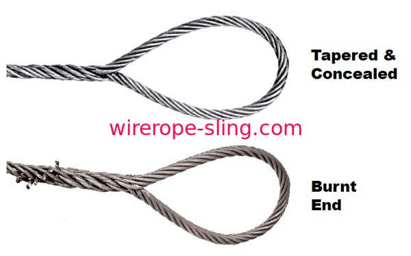
There are different types of wire rope splicing. The two more common ones areBack or end splicing – This is a type of splicing where rope end strands are directly spliced without making a loop. With this wire rope splicing, rope ends are drawn to a close to prevent fraying.
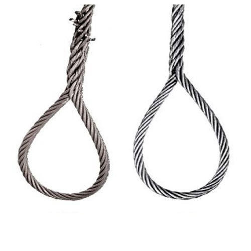
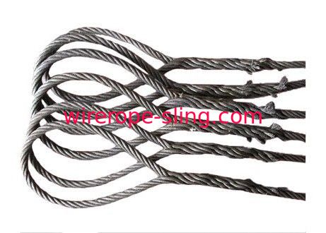
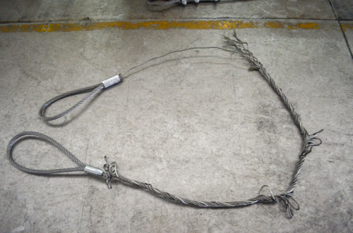
Eye splicing – This a more popular type of wire rope splicing which involves taking the working end of the rope to form a loop at the end. The end of the rope strands are unraveled, then passed over and under against the lay of the rope to interweave it back into the main length of the rope.
Wire rope splicing maintains almost 95% of the wire rope’s strength. You can employ splicing in three-strand braided ropes, or even in over 12-strand braided ropes.
Splicing lets you create a new rope of any length, alter an existing rope to suit a changing application, or repair a damaged wire rope. There are two main disadvantages to splicing – the expanding thickness of the line at the joint and the distortion in the shape of the rope.
Check the wire rope tools and accessories section of this website for more tools or fill out the enquiry form and let us help with your wire rope splicing needs.

We custom manufacture wire rope assemblies (endless loop) for conveyor lines. Our specialty is the Long splice. The Long splice is used to create a continuous or endless loop of wire rope cable frequently utilized on conveyor systems. The splice is a difficult multi-step labor intensive process in which two wire rope cable ends are joined end to end and the strands are intertwined to merge the two individual wire rope cable ropes ends.
Our proven experience can be viewed first hand in the quality of our wire rope cable splices we perform regularly for diverse clientele in the Unites States and around the world. For assistance with your unique wire rope conveyor cable splicing needs, please complete theor call us directly at
Manufacturer of aluminum swage sleeves including hour glass, oval, thin wall, combo & fiber rope sleeves. Hour glass sleeves range in rope & sleeve size from 1/32 to 1/2, width from .090 to 1.062, height from .136 to 1.625, hole width from .040 to .562, length from 1/4 to 2. Oval sleeves have a rope & sleeve size of 1/16, width of .172, height of .250, hole width of .078 & length of 3/8. Thin wall sleeves range in rope & sleeve size from 3/32 to 5/32, in width from .226 to .375, height from .372 to .562, hole width from .118 to .200 & length from 1/2 to 11/16. Combo sleeves are available with rope & sleeve size of 1/8 x 1/16, width of .343, height of .500, hole widths of .156 & .078 & length of 5/8 or sleeve size of 3/16 x 1/8, width of .430, height of .656, hole widths of .160 & .320 & length of 1. Fiber rope sleeves range in rope & sleeve size from 1/8 to 7/16, width from .250 to .855, height of .388 to 1.35, hold width from .160 to .525 & length from 1/2 to 1 1/4.
Whether you are looking for waterproof salon capes, salon chemical capes, ordinary hair cutting capes, or even special salon gowns such as customised barber capes, you can likely find them on Alibaba.com! Look out for amazing deals for these haircut hair catches and barber gowns and sell them to the many salons in the market! The beauty industry is constantly growing, and even in the worst of economic times, simple beauty tools, cosmetics, and treatments have continued to retain their market size and even growth. The lucrative market draws many barber and hairdresser salons to open at any one time, and you can in turn cater to this market with wholesale equipment and simple wares such as eye splice wire rope!
If you want to gain a competitive edge, you can even sell cute salon capes or cool barber capes with different colours or logo and design customisations. Some wholesalers that are also OEM manufacturers will allow you to do simple printing and customisations. This is especially if you order in large bulk quantities. You can also cater to the upmarket salons with high end salon capes that may be more sleek, made of more durable or slightly better materials. Look out for these eye splice wire rope wholesale or discuss with suppliers when making your purchases to check!

Understand that most of the people out from the industry always face the problem of having no idea with the terms of wire rope when receiving quotation. In this update, we will explain in the most simple way and hopefully it is applicable to anyone.
6X36 = Construction of wire rope (There are quite a lot different constructions available for different application for example like, 6X25, 6X29, 6X31, 4X39, 19X7, 8X26 etc.)
RHOL = Right hand ordinary lay, it is the wire lay direction and very important to select the right direction of wire when dealing with multi-reeving, crane and hoist application.
EIPS (1960) = Extra improved plow steel and 1960 stands for the tensile strength 1960N/mm2. The figure is telling you the grade of wire rope, lower or higher tensile strength will result in different breaking strength.
UNGALVD = Ungalvanized, the surface finishing of wire rope. Galvanized and Ungalvanized are the basic surface finishing selection with different grade of lubrication.
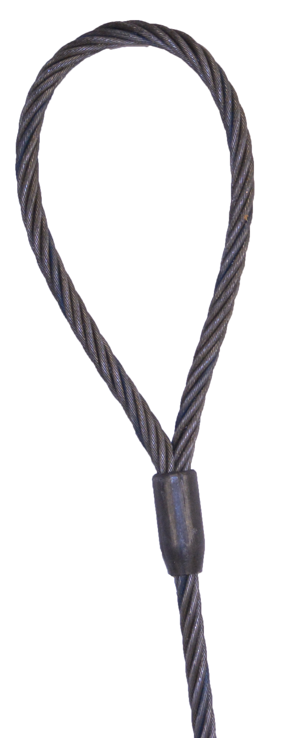
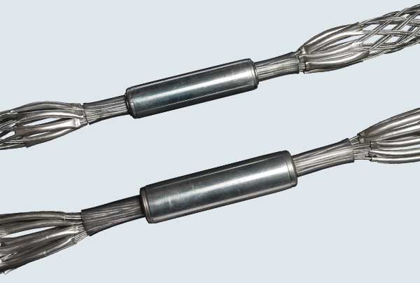
MECH SPLICED = Mechanical splicing is the process of using hydraulic pressure to press the aluminum sleeve or metal sleeve and a loop is formed. This phrase is always telling you the terminal of both end wire rope. It can be plain, socketed, fuse tapered or eye formed.
Wire rope could have a lot of variation upon the application which I will cover in the next update. The essay above is good enough to tell the basic and hope it helps for procurement department while dealing with steel wire rope. Last but not least, selecting the right wire rope is crucial to your company"s long term expenditure and safety purposes. Do not take the risk because of cheap.
Dec. 5, 1967 P. R. BAGBY IRE ROPE LONG SPLICE AND METHOD OF MAKING Filed May 7, 1965 Fxcer-4 l A VEN TOR. PERCY Q. SAC-15V ATTORNEYS United States Patent Ofiice 3,356,397 WIRE ROPE LONG SPLICE AND METHOD OF MAKING Percy R. Bagby, 27844 Conestoga Drive, Rolling Hills, Calif. 90274 Filed May 7, 1965, Ser. No. 453,950 2 Claims. (Cl. 287--78) The present invention relates to a wire rope pressed sleeve splice and to a method of making such a splice.
A common method of splicing wire rope is the long splice in which the two rope ends to be spliced are overlapped a predetermined length and the complemental strands of the rope ends are severed at longitudinallyspaced points. The conventional wire rope includes a core, and this core must be removed in the area adjacent the abutting ends of each pair of complemental strands in order to make the long splice. Each one of the severed ends is secured in position by tucking it into one of the open spaces formed by the removal of the fiber core. As many strand splices are formed as there are strands, and all of these splices constitute the long splice for the wire rope proper.
The prior art procedure for forming the long splice is a tedious and time-consuming operation, particularly that part of the operation in which the rope core is removed and replaced by the tucked ends of each complemental pair of strands in the rope. In addition, the procedure requires highly-skilled, experienced workmen, who may not readily be available when a wire rope unexpectedly parts. Nevertheless, this method of repairing wire rope has been used for many years because of certain advantages. That is, the strength of the wire rope is largely retained, losing only perhaps twenty percent because of the splice. This is apparently due to the appreciable length of the splice area which in a one-inch diameter rope may be 33 feet, with a 33-inch tuck for each of the strands. This length of splice provides a relatively large area of interengagement between the tucked strands and the adjacent strands so that the latter can exert a powerful clamping action and prevent the spliced ends from parting. In addition, the long splice is advantageous because the diameter of the wire rope in the splicearea is not appreciably increased. This in an important consideration in situations where the wire rope is, for example, formed into an endless loop for passage about sheaves and the like.
Accordingly, it is an object of the present invention to provide a method of long splicing the ends of a wire rope without the use of tucks while yet providing substantially the same tensile strength as the conventional, tucked long splice.
Another object of the invention is to provide a method of long splicing which can be quickly and easily accomplished by workmen having only a relatively rudimentary background in wire rope splicing techniques.
Another object of the invention is to provide a method of splicing the ends of a wire rope and which utilizes a plurality of pressed sleeves disposed about the rope. Each sleeve is applied to a strand splice and, by virtue of the number of such strand splices, the diameter and length of each sleeve can be reduced sufiiciently so as not to interfere with movement of the wire rope about sheaves or similar structure.
Another object of the invention is to provide a method of splicing or repairing a single damaged strand of a wire rope by pressing a sleeve about the damaged area.
Still another object of the invention is to provide a method of splicing a wire rope of that type having only circumferentially-arranged strands and no central core.
The present method is not limited to use with any particular length, diameter, number of strands, number 3,356,397 Patented Dec. 5, 1967 of wires per strand, wire arrangement, lay direction, lay type, type of core, or the like, and is applicable to the splicing or repair of wire ropes in general, as will be seen.
FIG. 1 is an elevational view of an exemplary short section of wire rope having six circumferentially arranged strands and a central fiber core, the rope section being shown parted in the middle;
FIG. 3 is a diagrammatic showing of the six strands of the wire rope of FIG. 1, illustrating the longitudinally spaced arrangement of the six splices over the splice length, the proximity of the splices being exaggerated so as to fit the drawing area;
FIG. 4 is an elevational view of a wire rope having six sleeves pressed about the rope to provide six splices longitudinally spaced along the splice length, the proximity of the splices being exaggerated to conform to the showing in FIG. 3;
FIG. 5 is an enlarged longitudinal cross-sectional view of one of the sleeves of FIG. 4, the sleeve being illustraed after it is pressed in position upon the wire rope; an
Referring now to the drawings, there is illustrated a conventional type of wire rope 10 having six outer strands 12, 14, 16, 18, 20 and 22 which are circumferentially arranged about a central fiber core 24. To facilitate the description which follows, the strands 12 through 20 of the rope end located to the left are designated a, while those in the rope end located to the right are designated b, as best viewed in FIGS. 1 and 3.
The wire rope 10 is merely exemplary and it will be understood that various other types of wire rope are equally suited for repair by use of the method and splice of the present invention.
According to the present method, the parted wire rope 10 is spliced by overlapping the rope ends a predetermined length sufficient to closely approach or equal the rated strength of the rope. In a one-inch rope this distance would be aproxirnately 33 feet. This overlap constitutes the splice area, and the individual strands are next severed, unlaid, and relaid in a particular manner toform the long splice. More particularly, ferrules or sleeves 26 are slid or threaded over the rope end to the left, out of the way of the splice area. Next, the strand 12a is unlaid from its rope end approximately the full length of the overlapped portion or splice length and severed. The corresponding strand 12b is then unlaid from its rope end and laid in the open groove formed in the first rope end by the removal of the strand 12a. The strands 12a and 1217 are then in end-abutting relation to define a splice joint. The fiber core 24 is preferably then severed the length of the strand 12a and the remaining core ends are abutted.
One of the sleeves 26 is next arranged about the adjacent pair of strands 12a and 12b and swaged or compressed over these strands. This also compresses the remaining strands of the rope end located on the left, as best seen in FIG. 3, and also compresses the core ends.
The tubular ferrules or sleeves 26 are made of any suitable high-strength material capable of cold flow under pressure into the wire and strand interstices of the rope ends. A sleeve of such material thus becomes an integral part of the rope and is capable of great holding power. Stainless steel is a preferred material because of its high strength and resistance to corrosion. High strength is desirable because it enables the use of relatively short, thin wall sleeves which facilitate movement of the rope about sheaves and the like. Preferably, the sleeve is kept below approximately twice the rope diameter, the sleeve lengthening somewhat during swaging. In this regard, it is noted that the swaging action compresses the wire rope, reducing its diameter somewhat, and also desirably reduces the thickness of the sleeve wall. In the example of the one-inch wire rope, the sleeve thickness is initially on the order of one-quarter inch when using stanless steel, that is, one-fourth the diameter of the wire rope. The finished diameter of the sleeve and rope would therefore be about one and one-eighth inches. Of course, the sleeve length and wall thickness will vary according to the wire rope diameter and type and the particular application for the wire rope.
After the strands 12a and 12b are sleeve-swaged together, the strand 14a is then severed at a point longitudinally spaced from the first splice but within the overlap or splice length. The strand 14b is then unlaid from its rope end and laid in the open groove formed by the removal of the strand 14a from the other rope end. The strand 14b is next severed to locate its severed end adjacent and in abutting relationship to the severed end of the strand 14a.
The operation is repeated with the strands 18a and 18b, the"strands 20a and 20b, and the strands 22a and 22b to provide the six splices illustrated in FIGS. 3 and 4. The six splices are illustrated in rather close proximity to enable their illustration in the space available. In actual practice the splices are located over a relatively long splice length, the length being approximately 33 feet for a one-inch wire rope, for example. Each splice is approximately six lays from the next splice.
The six splices constitute a long splice capable of carrying a load approaching or equaling the full rated strength of the wire rope, each of the sleeves developing approximately one-sixth of the load. Because the strength of the long splice is distributed over the six splice points, the cross section and length of each sleeve 26 can be reduced to a minimum. The use of the sleeves 26 thus provides a relatively quick and inexpensive means for long splicing wire rope. Tucks are completely eliminated. As a matter of fact, the present method can be used for splicing wire rope having no core, whereas the luck of a core greatly complicates present splicing practices since there is then no central core void within which to make tucks.
1. A long splice for the severed strands of a wire rope and adapted for passage about a sheave or the like, said long splice comprising: complemental pairs of the severed strands of the rope ends arranged in abutting relation to define splice joints, the abutting ends of each of said pairs being axially spaced from the abutting ends of the others of said pairs whereby said splice joints are axially spaced along said wire rope;
and a plurality of sleeves pressed upon said rope and about all of said strands, said sleeves being axially spaced to locate a separate one of said sleeves about each of said splice joints, the length of each said sleeve being approximately twice the diameter of said Wire rope, the wall thickness of each said sleeve being not more than approximately one-fourth the diameter of said wire rope, and the axial spacing between adjacent ones of said splice joints being such that, upon passage of said long splice portion of said wire rope about a usual sheave, the section of said wire rope between adjacent said sleeves engages upon the periphery of the sheave.

Mechanical Splice and Hand Splice, all slings are made from 6 x 19 EIP wire rope and tested to required load limits. As per OSHA requirements, each wire rope sling has a tag woven into the wire showing the required date and location of manufacture, the dimensions and load limits.

We "Pentest" from 1995are one of the leadingManufacturer, WholesalersandTrader ofUsha Martin Elevator Ropes, Wire Rope Slings and much more. Making use of quality tested material, our presented array of products are designed with high excellence. Extensively valued for their long service life, high strength and perfect finish, our provided products are highly commended.

When it comes to using wire rope slings in or on your jobsite, there are a few things to keep in mind in order to make sure that your wire rope sling is ready for use and that it will last for years to come. For starters, be sure to designate a qualified person to inspect all of your slings, fastenings, and attachment each day before use for damage or defects. A thorough inspection of your wire sling should check for:
By regularly performing these inspections that check the condition of your rope, you’ll not only be able to give your wire rope sling the care and maintenance that it needs to work at its best, you’ll be protecting your entire team and jobsite from the potential dangers that can occur if a wire rope sling snaps during use.
“Tough-Lock™” and “Cable-Flex™” slings are uniquely constructed unlike various return wire loop types. Note that our five step manufacturing process, commonly
All “Tough-Lock™” slings adhere and comply with current specifications of OSHA, ASME B30.9c-2000 Wire Rope Technical, and Associated Wire Rope Fabricators.

Located in northwest New Jersey, Jersey Strand and Cable, Inc. has been the most diversified fine diameter strand and cable manufacturer of its magnitude in the world for over 30 years. Our highly skilled and experienced staff provides our customers with the highest-quality standard and custom cable and stranded wire products available, including wire rope. Our innovative product development and unique custom cable manufacturing techniques allow us to provide micro-miniature, miniature, and small diameter wire sizes up to 1/8-inch finished product diameter.
With two state-of-the-art facilities in New Jersey that total over 100,000 square feet, Jersey Strand and Cable, Inc. is fulfilling a need in the industry for specialty cable and wire strand made to exact customer requirements. Our modern testing and development laboratory, along with other peripheral equipment and 200+ production machines, helps ensure that each customer’s product is manufactured and delivered to meet their precise specifications. Spearheaded by a former IBM systems engineer, we have developed a computerized, fully integrated management control system that controls and records all details of the manufacturing process, from RFQs to shipping and invoicing, to ensure that our products are adhering to customer and Jersey Strand and Cable, Inc. specifications. This system is efficient and streamlined and has been a huge factor in our success as the leading manufacturer of strand and cables.
As Sling Manufacturers, Hanes Supply"s sling production now includes chain slings, nylon slings, SlingMax slings and wire rope slings. Hanes Supply, Inc., has over 80 years experience splicing wire rope and manufacturing slings, as well as providing quality products to industry and the construction trades. Our expert staff is here to help you create lifting solutions for your lifting needs.
We stock a large variety of rigging gear and hardware. Our in-house services include inspection, test, and certifying of slings and rigging gear. We also offer on-site inspection of rigging, of rolex replica slings and rigging gear, on-site inspection of rigging, and pickup and delivery. We can have any of our experienced sales staff go on-site and assist with determining the best way to handle your lifting needs. We also offer an on site class on proper rigging gear inspection.

I&I Sling wire rope slings are mechanically spliced. Compared to loop back or turn back slings, mechanically spliced slings are considered to be the safer option due to the backup redundancy of the splice in the eye. This splice can keep the sling eye together in a situation where the pressed sleeve fails. Flemish Eye slings are fabricated at your local I&I Sling branch location with domestically sourced wire rope. Tight length tolerances are available, wire rope slings can be constructed with +/- the diameter of the rope or in matching sets. Flemish eye slings are compliant with ASME B30.9 and can be proof tested to twice the working load limit.


 8613371530291