
standing wire rope definition brands
In stricter senses, the term wire rope refers to a diameter larger than 9.5 mm (3⁄8 in), with smaller gauges designated cable or cords.wrought iron wires were used, but today steel is the main material used for wire ropes.
Historically, wire rope evolved from wrought iron chains, which had a record of mechanical failure. While flaws in chain links or solid steel bars can lead to catastrophic failure, flaws in the wires making up a steel cable are less critical as the other wires easily take up the load. While friction between the individual wires and strands causes wear over the life of the rope, it also helps to compensate for minor failures in the short run.
Wire ropes were developed starting with mining hoist applications in the 1830s. Wire ropes are used dynamically for lifting and hoisting in cranes and elevators, and for transmission of mechanical power. Wire rope is also used to transmit force in mechanisms, such as a Bowden cable or the control surfaces of an airplane connected to levers and pedals in the cockpit. Only aircraft cables have WSC (wire strand core). Also, aircraft cables are available in smaller diameters than wire rope. For example, aircraft cables are available in 1.2 mm (3⁄64 in) diameter while most wire ropes begin at a 6.4 mm (1⁄4 in) diameter.suspension bridges or as guy wires to support towers. An aerial tramway relies on wire rope to support and move cargo overhead.
Modern wire rope was invented by the German mining engineer Wilhelm Albert in the years between 1831 and 1834 for use in mining in the Harz Mountains in Clausthal, Lower Saxony, Germany.chains, such as had been used before.
Wilhelm Albert"s first ropes consisted of three strands consisting of four wires each. In 1840, Scotsman Robert Stirling Newall improved the process further.John A. Roebling, starting in 1841suspension bridge building. Roebling introduced a number of innovations in the design, materials and manufacture of wire rope. Ever with an ear to technology developments in mining and railroading, Josiah White and Erskine Hazard, principal ownersLehigh Coal & Navigation Company (LC&N Co.) — as they had with the first blast furnaces in the Lehigh Valley — built a Wire Rope factory in Mauch Chunk,Pennsylvania in 1848, which provided lift cables for the Ashley Planes project, then the back track planes of the Summit Hill & Mauch Chunk Railroad, improving its attractiveness as a premier tourism destination, and vastly improving the throughput of the coal capacity since return of cars dropped from nearly four hours to less than 20 minutes. The decades were witness to a burgeoning increase in deep shaft mining in both Europe and North America as surface mineral deposits were exhausted and miners had to chase layers along inclined layers. The era was early in railroad development and steam engines lacked sufficient tractive effort to climb steep slopes, so incline plane railways were common. This pushed development of cable hoists rapidly in the United States as surface deposits in the Anthracite Coal Region north and south dove deeper every year, and even the rich deposits in the Panther Creek Valley required LC&N Co. to drive their first shafts into lower slopes beginning Lansford and its Schuylkill County twin-town Coaldale.
The German engineering firm of Adolf Bleichert & Co. was founded in 1874 and began to build bicable aerial tramways for mining in the Ruhr Valley. With important patents, and dozens of working systems in Europe, Bleichert dominated the global industry, later licensing its designs and manufacturing techniques to Trenton Iron Works, New Jersey, USA which built systems across America. Adolf Bleichert & Co. went on to build hundreds of aerial tramways around the world: from Alaska to Argentina, Australia and Spitsbergen. The Bleichert company also built hundreds of aerial tramways for both the Imperial German Army and the Wehrmacht.
In the last half of the 19th century, wire rope systems were used as a means of transmitting mechanical powercable cars. Wire rope systems cost one-tenth as much and had lower friction losses than line shafts. Because of these advantages, wire rope systems were used to transmit power for a distance of a few miles or kilometers.
Steel wires for wire ropes are normally made of non-alloy carbon steel with a carbon content of 0.4 to 0.95%. The very high strength of the rope wires enables wire ropes to support large tensile forces and to run over sheaves with relatively small diameters.
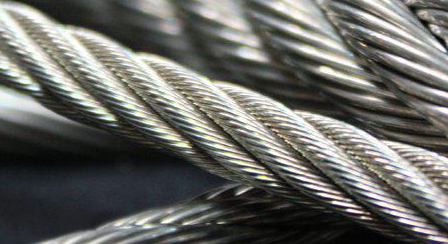
In the mostly used parallel lay strands, the lay length of all the wire layers is equal and the wires of any two superimposed layers are parallel, resulting in linear contact. The wire of the outer layer is supported by two wires of the inner layer. These wires are neighbors along the whole length of the strand. Parallel lay strands are made in one operation. The endurance of wire ropes with this kind of strand is always much greater than of those (seldom used) with cross lay strands. Parallel lay strands with two wire layers have the construction Filler, Seale or Warrington.
In principle, spiral ropes are round strands as they have an assembly of layers of wires laid helically over a centre with at least one layer of wires being laid in the opposite direction to that of the outer layer. Spiral ropes can be dimensioned in such a way that they are non-rotating which means that under tension the rope torque is nearly zero. The open spiral rope consists only of round wires. The half-locked coil rope and the full-locked coil rope always have a centre made of round wires. The locked coil ropes have one or more outer layers of profile wires. They have the advantage that their construction prevents the penetration of dirt and water to a greater extent and it also protects them from loss of lubricant. In addition, they have one further very important advantage as the ends of a broken outer wire cannot leave the rope if it has the proper dimensions.
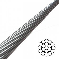
Stranded ropes are an assembly of several strands laid helically in one or more layers around a core. This core can be one of three types. The first is a fiber core, made up of synthetic material or natural fibers like sisal. Synthetic fibers are stronger and more uniform but cannot absorb much lubricant. Natural fibers can absorb up to 15% of their weight in lubricant and so protect the inner wires much better from corrosion than synthetic fibers do. Fiber cores are the most flexible and elastic, but have the downside of getting crushed easily. The second type, wire strand core, is made up of one additional strand of wire, and is typically used for suspension. The third type is independent wire rope core (IWRC), which is the most durable in all types of environments.ordinary lay rope if the lay direction of the wires in the outer strands is in the opposite direction to the lay of the outer strands themselves. If both the wires in the outer strands and the outer strands themselves have the same lay direction, the rope is called a lang lay rope (from Dutch langslag contrary to kruisslag,Regular lay means the individual wires were wrapped around the centers in one direction and the strands were wrapped around the core in the opposite direction.
Multi-strand ropes are all more or less resistant to rotation and have at least two layers of strands laid helically around a centre. The direction of the outer strands is opposite to that of the underlying strand layers. Ropes with three strand layers can be nearly non-rotating. Ropes with two strand layers are mostly only low-rotating.
Stationary ropes, stay ropes (spiral ropes, mostly full-locked) have to carry tensile forces and are therefore mainly loaded by static and fluctuating tensile stresses. Ropes used for suspension are often called cables.
Track ropes (full locked ropes) have to act as rails for the rollers of cabins or other loads in aerial ropeways and cable cranes. In contrast to running ropes, track ropes do not take on the curvature of the rollers. Under the roller force, a so-called free bending radius of the rope occurs. This radius increases (and the bending stresses decrease) with the tensile force and decreases with the roller force.
Wire rope slings (stranded ropes) are used to harness various kinds of goods. These slings are stressed by the tensile forces but first of all by bending stresses when bent over the more or less sharp edges of the goods.
Technical regulations apply to the design of rope drives for cranes, elevators, rope ways and mining installations. Factors that are considered in design include:
Donandt force (yielding tensile force for a given bending diameter ratio D/d) - strict limit. The nominal rope tensile force S must be smaller than the Donandt force SD1.
The wire ropes are stressed by fluctuating forces, by wear, by corrosion and in seldom cases by extreme forces. The rope life is finite and the safety is only ensured by inspection for the detection of wire breaks on a reference rope length, of cross-section loss, as well as other failures so that the wire rope can be replaced before a dangerous situation occurs. Installations should be designed to facilitate the inspection of the wire ropes.
Lifting installations for passenger transportation require that a combination of several methods should be used to prevent a car from plunging downwards. Elevators must have redundant bearing ropes and a safety gear. Ropeways and mine hoistings must be permanently supervised by a responsible manager and the rope must be inspected by a magnetic method capable of detecting inner wire breaks.
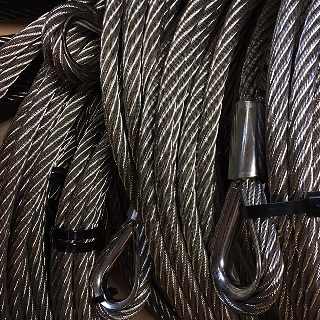
The end of a wire rope tends to fray readily, and cannot be easily connected to plant and equipment. There are different ways of securing the ends of wire ropes to prevent fraying. The common and useful type of end fitting for a wire rope is to turn the end back to form a loop. The loose end is then fixed back on the wire rope. Termination efficiencies vary from about 70% for a Flemish eye alone; to nearly 90% for a Flemish eye and splice; to 100% for potted ends and swagings.
When the wire rope is terminated with a loop, there is a risk that it will bend too tightly, especially when the loop is connected to a device that concentrates the load on a relatively small area. A thimble can be installed inside the loop to preserve the natural shape of the loop, and protect the cable from pinching and abrading on the inside of the loop. The use of thimbles in loops is industry best practice. The thimble prevents the load from coming into direct contact with the wires.
A wire rope clip, sometimes called a clamp, is used to fix the loose end of the loop back to the wire rope. It usually consists of a U-bolt, a forged saddle, and two nuts. The two layers of wire rope are placed in the U-bolt. The saddle is then fitted to the bolt over the ropes (the saddle includes two holes to fit to the U-bolt). The nuts secure the arrangement in place. Two or more clips are usually used to terminate a wire rope depending on the diameter. As many as eight may be needed for a 2 in (50.8 mm) diameter rope.
The mnemonic "never saddle a dead horse" means that when installing clips, the saddle portion of the assembly is placed on the load-bearing or "live" side, not on the non-load-bearing or "dead" side of the cable. This is to protect the live or stress-bearing end of the rope against crushing and abuse. The flat bearing seat and extended prongs of the body are designed to protect the rope and are always placed against the live end.
An eye splice may be used to terminate the loose end of a wire rope when forming a loop. The strands of the end of a wire rope are unwound a certain distance, then bent around so that the end of the unwrapped length forms an eye. The unwrapped strands are then plaited back into the wire rope, forming the loop, or an eye, called an eye splice.
A Flemish eye, or Dutch Splice, involves unwrapping three strands (the strands need to be next to each other, not alternates) of the wire and keeping them off to one side. The remaining strands are bent around, until the end of the wire meets the "V" where the unwrapping finished, to form the eye. The strands kept to one side are now re-wrapped by wrapping from the end of the wire back to the "V" of the eye. These strands are effectively rewrapped along the wire in the opposite direction to their original lay. When this type of rope splice is used specifically on wire rope, it is called a "Molly Hogan", and, by some, a "Dutch" eye instead of a "Flemish" eye.
Swaging is a method of wire rope termination that refers to the installation technique. The purpose of swaging wire rope fittings is to connect two wire rope ends together, or to otherwise terminate one end of wire rope to something else. A mechanical or hydraulic swager is used to compress and deform the fitting, creating a permanent connection. Threaded studs, ferrules, sockets, and sleeves are examples of different swaged terminations.
A wedge socket termination is useful when the fitting needs to be replaced frequently. For example, if the end of a wire rope is in a high-wear region, the rope may be periodically trimmed, requiring the termination hardware to be removed and reapplied. An example of this is on the ends of the drag ropes on a dragline. The end loop of the wire rope enters a tapered opening in the socket, wrapped around a separate component called the wedge. The arrangement is knocked in place, and load gradually eased onto the rope. As the load increases on the wire rope, the wedge become more secure, gripping the rope tighter.
Poured sockets are used to make a high strength, permanent termination; they are created by inserting the wire rope into the narrow end of a conical cavity which is oriented in-line with the intended direction of strain. The individual wires are splayed out inside the cone or "capel", and the cone is then filled with molten lead-antimony-tin (Pb80Sb15Sn5) solder or "white metal capping",zincpolyester resin compound.
Donald Sayenga. "Modern History of Wire Rope". History of the Atlantic Cable & Submarine Telegraphy (atlantic-cable.com). Archived from the original on 3 February 2014. Retrieved 9 April 2014.
A competent person must begin a visual inspection prior to each shift the equipment is used, which must be completed before or during that shift. The inspection must consist of observation of wire ropes (running and standing) that are likely to be in use during the shift for apparent deficiencies, including those listed in paragraph (a)(2) of this section. Untwisting (opening) of wire rope or booming down is not required as part of this inspection.
Significant distortion of the wire rope structure such as kinking, crushing, unstranding, birdcaging, signs of core failure or steel core protrusion between the outer strands.
In running wire ropes: Six randomly distributed broken wires in one rope lay or three broken wires in one strand in one rope lay, where a rope lay is the length along the rope in which one strand makes a complete revolution around the rope.
In rotation resistant ropes: Two randomly distributed broken wires in six rope diameters or four randomly distributed broken wires in 30 rope diameters.
In pendants or standing wire ropes: More than two broken wires in one rope lay located in rope beyond end connections and/or more than one broken wire in a rope lay located at an end connection.
If a deficiency in Category I (see paragraph (a)(2)(i) of this section) is identified, an immediate determination must be made by the competent person as to whether the deficiency constitutes a safety hazard. If the deficiency is determined to constitute a safety hazard, operations involving use of the wire rope in question must be prohibited until:
If the deficiency is localized, the problem is corrected by severing the wire rope in two; the undamaged portion may continue to be used. Joining lengths of wire rope by splicing is prohibited. If a rope is shortened under this paragraph, the employer must ensure that the drum will still have two wraps of wire when the load and/or boom is in its lowest position.
If a deficiency in Category II (see paragraph (a)(2)(ii) of this section) is identified, operations involving use of the wire rope in question must be prohibited until:
The employer complies with the wire rope manufacturer"s established criterion for removal from service or a different criterion that the wire rope manufacturer has approved in writing for that specific wire rope (see § 1926.1417),
If the deficiency is localized, the problem is corrected by severing the wire rope in two; the undamaged portion may continue to be used. Joining lengths of wire rope by splicing is prohibited. If a rope is shortened under this paragraph, the employer must ensure that the drum will still have two wraps of wire when the load and/or boom is in its lowest position.
If the deficiency (other than power line contact) is localized, the problem is corrected by severing the wire rope in two; the undamaged portion may continue to be used. Joining lengths of wire rope by splicing is prohibited. Repair of wire rope that contacted an energized power line is also prohibited. If a rope is shortened under this paragraph, the employer must ensure that the drum will still have two wraps of wire when the load and/or boom is in its lowest position.
Where a wire rope is required to be removed from service under this section, either the equipment (as a whole) or the hoist with that wire rope must be tagged-out, in accordance with § 1926.1417(f)(1), until the wire rope is repaired or replaced.
Wire ropes on equipment must not be used until an inspection under this paragraph demonstrates that no corrective action under paragraph (a)(4) of this section is required.
At least every 12 months, wire ropes in use on equipment must be inspected by a qualified person in accordance with paragraph (a) of this section (shift inspection).
The inspection must be complete and thorough, covering the surface of the entire length of the wire ropes, with particular attention given to all of the following:
Exception: In the event an inspection under paragraph (c)(2) of this section is not feasible due to existing set-up and configuration of the equipment (such as where an assist crane is needed) or due to site conditions (such as a dense urban setting), such inspections must be conducted as soon as it becomes feasible, but no longer than an additional 6 months for running ropes and, for standing ropes, at the time of disassembly.
If the deficiency is localized, the problem is corrected by severing the wire rope in two; the undamaged portion may continue to be used. Joining lengths of wire rope by splicing is prohibited. If a rope is shortened under this paragraph, the employer must ensure that the drum will still have two wraps of wire when the load and/or boom is in its lowest position.

Any wire rope in use should be inspected on a regular basis. You have too much at stake in lives and equipment to ignore thorough examination of the rope at prescribed intervals.
The purpose of inspection is to accurately estimate the service life and strength remaining in a rope so that maximum service can be had within the limits of safety. Results of the inspection should be recorded to provide a history of rope performance on a particular job.
On most jobs wire rope must be replaced before there is any risk of failure. A rope broken in service can destroy machinery and curtail production. It can also kill.
Because of the great responsibility involved in ensuring safe rigging on equipment, the person assigned to inspect should know wire rope and its operation thoroughly. Inspections should be made periodically and before each use, and the results recorded.
When inspecting the rope, the condition of the drum, sheaves, guards, cable clamps and other end fittings should be noted. The condition of these parts affects rope wear: any defects detected should be repaired.
To ensure rope soundness between inspections, all workers should participate. The operator can be most helpful by watching the ropes under his control. If any accident involving the ropes occurs, the operator should immediately shut down his equipment and report the accident to his supervisor. The equipment should be inspected before resuming operation.
The Occupational Safety and Health Act has made periodic inspection mandatory for most wire rope applications. If you need help locating the regulations that apply to your application, please give our rigging experts a call.
PersonalWe are on hand to personally guide you through the entire process, we translate the jargon, we recommend what’s best, and we are always here in person. No nonsense, just straight talking people who always exceed expectations through our extensive wire rope knowledge and superior service.
Trust & ExpertiseOur international supply network incorporates a wide range of partners with whom we hold long standing relationships; meaning we supply quality assured and fully traceable products all over the globe
On 28th April 2017 Redaelli entered Teufelberger Group. Teufelberger and Redaelli both leading manufacturers of high performance steel wire ropes, unite their expertise to provide the best technical solutions for steel wire ropes and establish together a global presence.
We at Teufelberger-Redaelli understand your day-to-day challenges and solve them together with you. We develop and produce high performance steel wire ropes that create added value by enhancing the efficiency and safety of your applications. Expect more: of our innovative steel wire ropes, our services, our experienced experts in development, application engineering, and sales – all around the globe. Being a family enterprise, we attach great importance to successful, long-standing business relationships. Our commitment does not begin and end solely with the supply of premium quality steel wire ropes, but we also accompany you throughout your work processes when it comes to optimizing efficiency and costs.
We know that high performance steel wire ropes are able to unleash their full potential only if crane systems have been set up optimally and if the ropes have been installed correctly. Therefore, we also provide support during project planning, installation, and subsequent careful handling to maximize rope lifetimes. After all, the purchasing costs are just the tip of the iceberg.
Rotation-resistant and non-rotation-resistant high performance steel wire ropes from Teufelberger-Redaelli are used for a variety of applications such as:
Four manufacturing sites for steel wire ropes and a combined total of more than 425 years of rope-making experience tally up to a unique wealth of expertise and an unmatched and proven production standard. The resulting high degree of flexibility allows us to keep delivery times to a minimum.
Wire rope is a complex mechanical device that has many moving parts all working in tandem to help support and move an object or load. In the lifting and rigging industries, wire rope is attached to a crane or hoist and fitted with swivels, shackles or hooks to attach to a load and move it in a controlled matter. It can also be used to lift and lower elevators, or as a means of support for suspension bridges or towers.
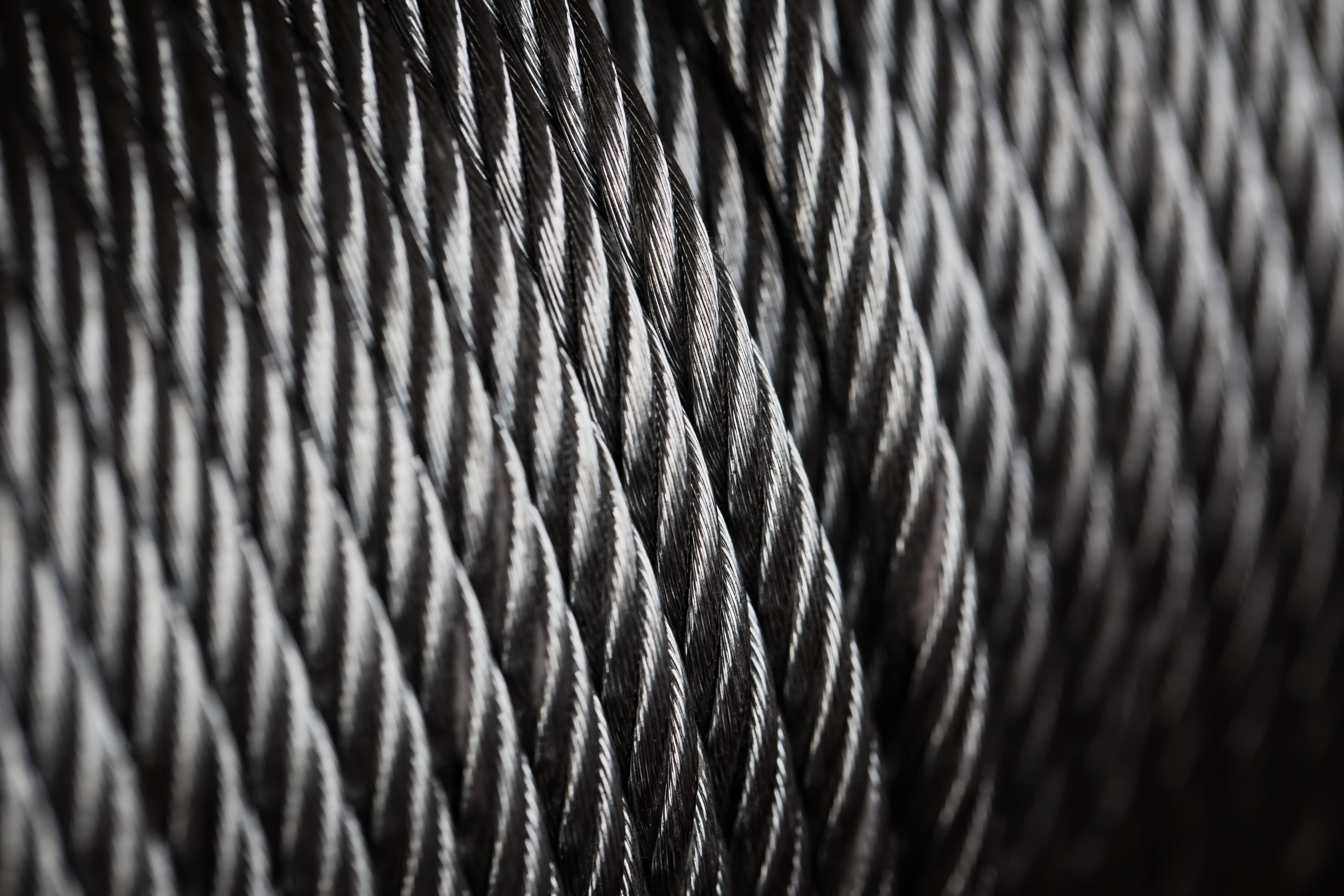
Wire rope is a preferred lifting device for many reasons. Its unique design consists of multiple steel wires that form individual strands laid in a helical pattern around a core. This structure provides strength, flexibility, and the ability to handle bending stresses. Different configurations of the material, wire, and strand structure will provide different benefits for the specific lifting application, including:Strength
However, selecting the proper wire rope for your lifting application requires some careful thought. Our goal is to help you understand the components of a wire rope, the construction of wire rope, and the different types of wire rope and what they might be used for. This will allow you to select the best performing and longest-lasting wire rope for the job at hand.
A wire rope is, in reality, a very complicated machine. A typical 6 x 25 rope has 150 wires in its outer strands, all of which move independently and together in a very complicated pattern around the core as the rope bends. Clearances between wires and strands are balanced when a rope is designed so that proper bearing clearances will exist to permit internal movement and adjustment of wires and strands when the rope has to bend. These clearances will vary as bending occurs, but are of the same range as the clearances found in automobile engine bearings.
Understanding and accepting the “machine idea” gives a rope user a greater respect for rope, and enables them to obtain better performance and longer useful life from rope applications. Anyone who uses a rope can use it more efficiently and effectively when they fully understand the machine concept.
Wires are the smallest component of wire rope and they make up the individual strands in the rope. Wires can be made from a variety of metal materials including steel, iron, stainless steel, monel, and bronze. The wires can be manufactured in a variety of grades that relate to the strength, resistance to wear, fatigue resistance, corrosion resistance, and curve of the wire rope.
Strands of wire rope consist of two or more wires arranged and twisted in a specific arrangement. The individual strands are then laid in a helical pattern around the core of the rope.
The core of a wire rope runs through the center of the rope and supports the strands and helps to maintain their relative position under loading and bending stresses. Cores can be made from a number of different materials including natural or synthetic fibers and steel.
Lubrication is applied during the manufacturing process and penetrates all the way to the core. Wire rope lubrication has two primary benefits:Reduces friction as the individual wires and strands move over each other
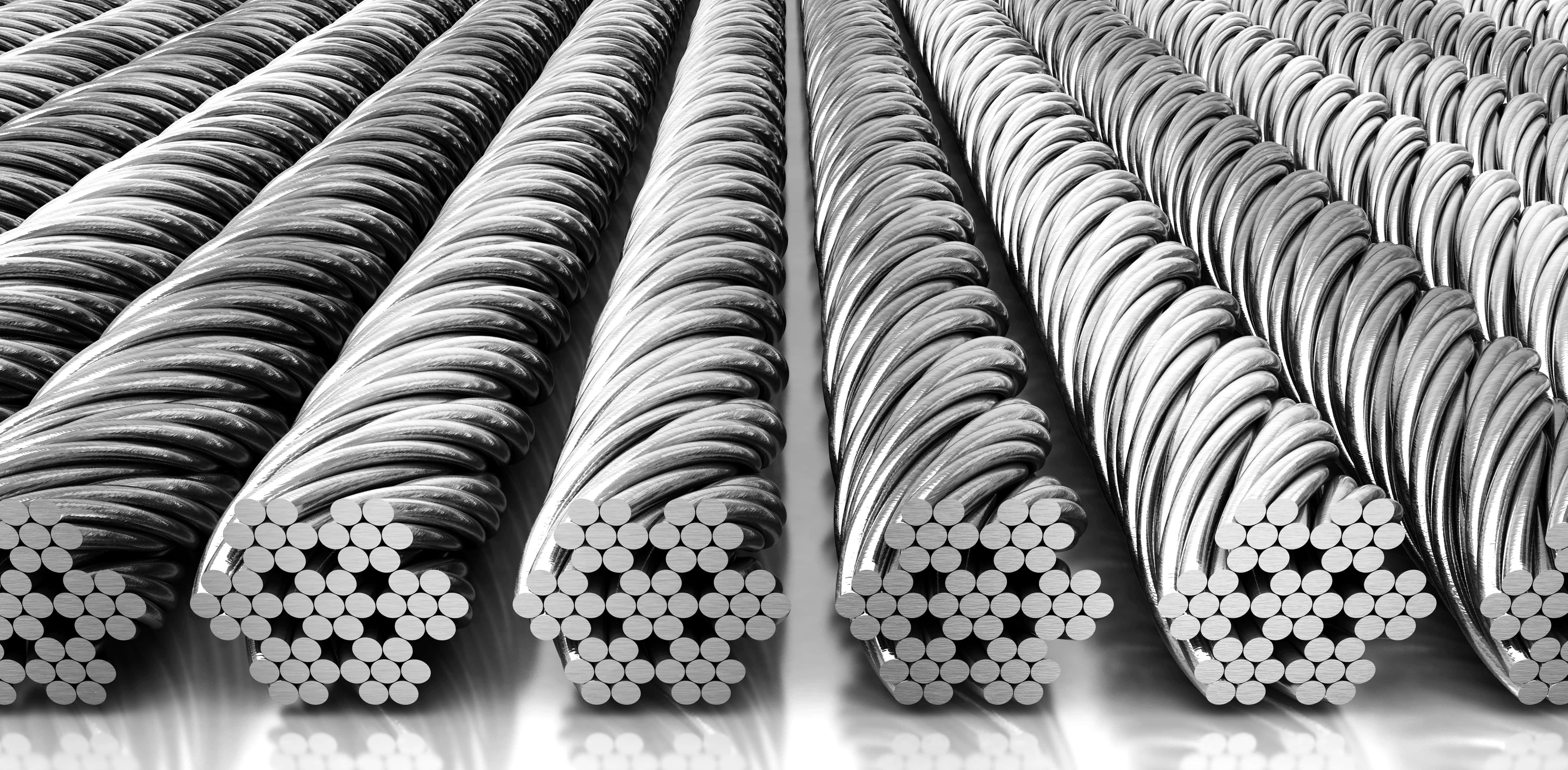
The number of layers of wires, the number of wires per layer, and the size of the wires per layer all affect the strand pattern type. Wire rope can be constructed using one of the following patterns, or can be constructed using two or more of the patterns below.Single Layer – The most common example is a 7 wire strand with a single-wire center and six wires of the same diameter around it.
Filler Wire – Two layers of uniform-size wire around a center with the inner layer having half the number of wires as the outer layer. Small filler wires, equal to the number in the inner layer, are laid in valleys of the inner wire.
Seale – Two layers of wires around a center with the same number of wires in each layer. All wires in each layer are the same diameter. The large outer wires rest in the valleys between the smaller inner wires.
Warrington – Two layers of wires around a center with one diameter of wire in the inner layer, and two diameters of wire alternating large and small in the outer later. The larger outer-layer wires rest in the valleys, and the smaller ones on the crowns of the inner layer.
On a preformed wire rope, the strands and wires are formed during the manufacturing process to the helical shape that they will take in a finished wire rope.
Preformed rope can be advantageous in certain applications where it needs to spool more uniformly on a drum, needs greater flexibility, or requires more fatigue-resistance when bending.
Direction and type of lay refer to the way the wires are laid to form a strand (either right or left) and how the strands are laid around the core (regular lay, lang lay, or alternate lay).Regular Lay – The wires line up with the axis of the rope. The direction of the wire lay in the strand is opposite to the direction of the strand lay. Regular lay ropes are more resistant to crushing forces, are more naturally rotation-resistant, and also spool better in a drum than lang lay ropes.
Lang Lay– The wires form an angle with the axis of the rope. The wire lay and strand lay around the core in the same direction. Lang Lay ropes have a greater fatigue-resistance and are more resistant to abrasion.
A steel core can be an independent wire rope or an individual strand. Steel cores are best suited for applications where a fiber core may not provide adequate support, or in an operating environment where temperatures could exceed 180° F.
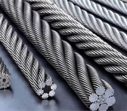
The classifications of wire rope provide the total number of strands, as well as a nominal or exact number of wires in each strand. These are general classifications and may or may not reflect the actual construction of the strands. However, all wire ropes of the same size and wire grade in each classification will have the SAME strength and weight ratings and usually the same pricing.
Besides the general classifications of wire rope, there are other types of wire rope that are special construction and designed for special lifting applications.
Some types of wire rope, especially lang lay wire rope, are more susceptible to rotation when under load. Rotation resistant wire rope is designed to resist twisting, spinning, or rotating and can be used in a single line or multi-part system.
Special care must be taken when handling, unreeling, and installing rotation resistant wire rope. Improper handling or spooling can introduce twist into the rope which can cause uncontrolled rotation.
Compacted strand wire rope is manufactured using strands that have been compacted, reducing the outer diameter of the entire strand, by means of passing through a die or rollers. This process occurs prior to closing of the rope.
This process flattens the surface of the outer wires in the strand, but also increases the density of the strand. This results in a smoother outer surface and increases the strength compared to comparable round wire rope (comparing same diameter and classification), while also helping to extend the surface life due to increased wear resistance.
A swaged wire rope differs from a compacted strand wire rope, in that a swaged wire rope’s diameter is compacted, or reduced, by a rotary swager machine after the wire rope has been closed. A swaged wire rope can be manufactured using round or compacted strands.
The advantages of a swaged wire rope are that they are more resistant to wear, have better crushing resistance, and high strength compared to a round strand wire rope of equal diameter and classification. However, a swaged wire rope may have less bending fatigue resistance.
A plastic coating can be applied to the exterior surface of a wire rope to provide protection against abrasion, wear, and other environmental factors that may cause corrosion. However, because you can’t see the individual strands and wires underneath the plastic coating, they can be difficult to inspect.
Plastic filled wire ropes are impregnated with a matrix of plastic where the internal spaces between the strands and wires are filled. Plastic filling helps to improve bending fatigue by reducing the wear internally and externally. Plastic filled wire ropes are used for demanding lifting applications.
This type of wire rope uses an Independent Wire Rope Core (IWRC) that is either filled with plastic or coated in plastic to reduce internal wear and increase bending fatigue life.
Remember, wire rope is a complex piece of mechanical machinery. There are a number of different specifications and properties that can affect the performance and service life of wire rope. Consider the following when specifying the best type of wire rope for your lifting application:Strength
When you select a piece of rope that is resistant to one property, you will most likely have a trade-off that affects another property. For example, a fiber core rope will be more flexible, but may have less crushing resistance. A rope with larger diameter wires will be more abrasion resistant, but will offer less fatigue resistance.
At Mazzella Companies, we offer all different kinds of wire rope from all of the leading manufacturers. We sell the highest-quality domestic and non-domestic rigging products because product quality and operating safety go hand-in-hand. We have one of the largest and most complete inventories of both domestic and non-domestic rigging and lifting products to suit your lifting needs.
If you’re looking for a standard or custom specified wire rope for your lifting project, contact a Lifting Specialist at a Mazzella Companies location near you.
We stock well over 2,000,000 feet of wire rope in our various locations … ready for immediate delivery! We provide wire rope assemblies, and manufacture bridge cables, crane cables, steel mill cables, and thousands of OEM assemblies.
We develop and manufacture strands and ropes, in the fine rope range with diameters from 0.09 to 8.0 mm, for the most diverse technical requirements, with individual specifications. This results in different requirements for the material, the rope structure and the diameter range. In our rope factory, ropes can be manufactured in different lay directions. Our standard material stainless steel 1.4401 is predominantly used for a wide variety of constructions. Depending on the requirements, we also supply ropes in special materials or process them by, for example, hammering, purifying or PU coating. We produce our ropes with fiber or steel core. We also offer conducting wire ropes of the e-rope brand. The thinnest wire processed in our rope factory for use in microtechnology has a diameter of 0.015 mm. This corresponds to 1/4 the diameter of a human hair. These wire ropes are used, for example, in medical devices. Our ropes are durable quality products and thus contribute to the sustainability of the products in which they are processed.
Your crane"s wire rope works hard. (Almost as hard as you do.) It can deteriorate more quickly than you might think, posing a real danger for you and your crew. In this article, we"ll answer the following questions.
Before we get into that, let"s take a brief moment to go over the proper wire terminology. Understanding the make-up of the wire rope allows you to have a clear understanding of when the rope needs to be replaced.
Flexible steel wire rope is made up of individual wires that make up a strand; these strands are then wrapped around a central core to make up a rope.
Understanding the difference between a wire and a strand is critical. If a strand (grouping of wires) in the rope breaks, the crane wire would need to be replaced. However, if a single wire in the strand breaks, the rope itself may still be usable.
Rag & Visual Inspections: In this method, you use a rag in your inspection, pulling it slowly across the strand, stopping for a closer and more detailed inspection wherever the rag gets caught on a wire.
The Diameter Measurement Method: This method involves comparing the diameter of your rope at various intervals with the rope"s official diameter per the manufacturer"s guidelines. A variation in the rope"s diameter can alert you to potential interior damage that a visual inspection would miss.
Localized Flaw Inspections (LF) vs. Loss of Metallic Area Inspections (LMA) - Both methods use electromagnetics to search for a wire rope"s internal damage.
According to OSHA"s safety regulations, you"re required to inspect your crane"s wire ropes at least every 12 months by qualified professionals. However, OSHA and other experts also recommend inspecting your wire ropes more frequently, such as after every initial installation or repair, or daily before each shift to ensure a safe work environment.
As discussed at the very beginning of this article, we can break down wire rope into three parts. First, wires, which make up strands, and then the strands wrapped around the central core make the rope. Of your total number of wires, you never want more than 10% to be damaged before you need to look into crane wire rope replacement.
The Jimmy Green Marine Rigging Team invite you to try our wire rigging service involving the meticulous production of complete rigging wires to your exact lengths and specifications.
Jimmy Green Marine offer a comprehensive range of wire rope terminals suitable for marine and architectural applications to complement the stainless steel wire. More obscure fittings can be obtained from our Rigging Manufacturer partners at reasonable notice to solve any rigging issues.
Leading marine industry manufacturers such as Sta-Lok, Petersen Stainless, Hamma, BSI, Selden, Bluewave andKOS are carefully sourced to ensure all our completed wire rigging is of the highest possible quality.
Jimmy Green produce Wire Rigging on machines recognised as the best in the marine industry - a modern, up-to-date, maintained and serviced WireTechnik Hydraulic Roller Press and multiple Cabco Talurit Hydraulic Presses are on hand in our Rigging Workshop at Jimmy Green to carry out the work.
Strict Quality Control Procedures and Accountability Systems ensure that only the best quality stainless steel wire and terminals are considered. Traceability is an essential feature of the Jimmy Green assurance policy: Stainless Steel Wire - Quality Control and Care
Jimmy Green Marine also offer the full range of Sta-Lok, Petersen Hi-Mod and Bluewave Swageless DIY fittings, plus Norseman replacement cones manufactured by Tylaska Marine. These are standing rigging essentials for wire rigging solutions involving one end swaged and the other end left long for finishing in situ.
The Jimmy Green Custom Build Online System makes an instant online quote very achievable, even with only the basic information on your standing rigging.
Once the specification is finalised and the price is established, each wire stay, shroud or other finished wire rigging component can be added to your basket to purchase.
Confirming the correct T terminals to fit your mast backing plates with proper load-bearing seating is extremely important to the integrity of your rig.
However, for an indicative quote, the T terminals are similarly priced for each wire diameter, so it is possible to select a generic one to estimate a price.

As already discussed on the ‘Measuring the rope diameter‘ page and on the ‘Break-In-Period‘ page, shortly after installation, the wire rope diameter will slightly decrease. This is normal and is caused by the adjustment of all rope elements when loaded the first time. To evaluate the diameter reduction, you have to measure the rope when new, and you also have to measure the rope after the break in period at a specified load. This gives you a good indication of the magnitude of the initial diameter reduction in your specific application. The diameter reading you took after the break in period should now become your ‘gauge’. Do not compare the rope diameter you are about to take with the ‘catalogue’ diameter. It may give you a false indication, since wire rope may have a plus tolerance of up to 4% to 5% over the ‘catalogue’ diameter.
If you detect a further diameter reduction when measuring the rope under the same load condition as after the break in period, it is often due to excessive abrasion of the outside wires, loss of core support, internal or external corrosion, inner wire failures, and/or inner wire abrasion. However, there will always be a normal continuous small decrease in diameter throughout the rope’s service life.
Deciding whether or not a rope is safe is not always a simple matter. A number of different but interrelated conditions must be evaluated. It would be dangerously unwise for an inspector to declare a rope ‘safe’ for continued service simply because its diameter had not reached a certain minimum diameter if, at the same time, other observations led to a different conclusion.
However, ASME, ISO 4309, CSA, other Canadian Provincial H&SA and USA OSHA Regulation have various values published for maximum allowable diameter reductions. They are somewhat confusing as they show diameter reduction values from 3.5% to 9%, and some give reduction values in inch fractions depending on rope nominal diameter.

THERE are four varieties of rope in the United States naval service: that made of the fibres of the hemp plant; the Manilla rope, made of the fibres of a species of the wild banana; hide rope, made of strips of green hide, and wire rope.
In some countries, ropes made of horse hair, of the fibrous husk of the cocoanut, called coir-rope, and of tough grasses, are quite common. In our own country, rope has been made from the flax and cotton plants. The metals have also been put in requisition, copper-wire rope being used for particular purposes, principally for lightning conductors, and iron and steel wire are in general use for standing rigging; steel wire being some fifty per cent. stronger than iron wire of the same size.
Of the many vegetable substances that are adapted to rope-making, the best is hemp-hemp-rope possessing in a remarkable degree the essential qualities of flexibility and tenacity.
Hemp in its transit from its native fields to the ropewalk passes through the operations of dew-rotting, scotching and hackling. In the first process water dissolves the glutinous matter that binds the fibrous portion to the woody core, thus partly setting the fibres free; scotching breaks the stalk and separates it still further from the fibre, and hackling consists in combing out the hemp to separate the long and superior fibres from the short and indifferent ones or tow.
The hemp of commerce is put up in bundles of about 200 lbs. each. If good, it will be found to possess a long, thin fibre, smooth and glossy on the surface, and of a yellowish green color; free from "spills" or small pieces of the woody substance; possessing the requisite properties of strength and toughness, and inodorous.
Russian and Italian hemp are considered the best, for the generality of purposes. Rope made from the best quality of Russian hemp, is more extensively used in the navy than any other kind.
The size of Rope is denoted by its circumference, and the length is measured by the fathom. The cordage allowed in the equipment of a man-of-war ranges from 1 1/4 (15-thread) to 10 inches inclusive.
Varieties of Rope. In rope-making the general rule is to spin the yarn from right over to left. All rope yarns are therefore right-handed. The strand, or ready, formed by a combination of such yarns, becomes left-handed. Three of these strands being twisted together form a right-handed rope, known as plain-laid rope. Fig. 14, Plate 7.
White Rope. Hemp rope, when plain-laid and not tarred in laying-up, is called white rope, and is the strongest hemp cordage. It should not be confounded with Manilla. It is used for log-lines and signal halliards. The latter are also made of yarns of untarred hemp, plaited by machinery to avoid the kinking common to new rope of the ordinary make. This is called "plaited stuff," or "signal halliard stuff."
The tarred plain-laid ranks next in point of strength, and is in more general use than any other. The lighter kinds of standing rigging, much of the running rigging, and many purchase falls are made of this kind of rope.
Cable-laid or Hawser-laid Rope, Fig. 15, is left-handed rope of nine strands, and is so made to render it impervious to water, but the additional twist necessary to lay it up seems to detract from the strength of the fibre, the strength of plain-laid being to that of cable-laid as 8.7 to 6; besides this, it stretches considerably under strain.
Shroud-laid. Rope, Fig. 16, Plate 7, is formed by adding another strand to the plain-laid rope. But the four spirals of strands leave a hollow in the centre, which, if unfilled, would, on the application of strain, permit the strands to sink in, and detract greatly from the rope"s strength, by an unequal distribution of strain. The four strands are, therefore, laid up around a heart, a small rope, made soft and elastic, and about one-third the size of the strands.
Experiments show that four-stranded rope, when under 5 inches, is weaker than three-stranded of the same size; but from 5 to 8 inches, the difference in strength of the two kinds is trifling, while all above 8 inches is considered to be equal to plain-laid when the rope is well made.
Tapered Rope is used where much strain is brought on only one end. That part which bears the strain is full-sized, tapering off to the hauling part, which is light and pliable. Fore and main tacks and sheets are made of tapered rope.
Twice-laid Rope is made from second-hand yarns. This rope may be readily known by the different shades of color of the yarns, but it is often difficult to determine, by mere inspection, whether it is relaid from what was good rope, and, consequently, still good, or made up from junk or condemned rigging, and worthless. Twice-laid rope is only met with on board ship when necessity has compelled its purchase on foreign stations.
Manilla Rope seems to be better adapted to certain purposes on board ship than hemp, being more pliable, buoyant, causing less friction, and not so easily affected by moisture. It is used for hawsers, tow-lines, and for light-running rigging and gun-tackle falls. Manilla is now less used in the navy than formerly. The Book of Allowances states that the cheap first cost of Manilla as compared with hemp is more than compensated by the greater market value of the hemp when worn-out. This statement is not correct if applied to the current relative values of hemp and Manilla junk in this country.
Hide Rope is made of strips cut by machinery from green hides. Formerly used for topsail tyes, and for tailing on to such ropes as are exposed to much chafe in some particular part, as topsail sheets, etc., it is now allowed only for wheel ropes. Its strength is about one-third that of hemp.
Hide rope requires care to keep it in good order, and should not be exposed to the weather unnecessarily. It should be given a lick of thin tar (Swedish preferred)
Avoid serving the splices of hide rope. When spare wheel ropes are stowed away they should be well oiled and headed up in a barrel to preserve them from rats and mice.
Wire Rope for general use in the navy is made from one quarter to seven inches, inclusive, in circumference, those being the maximum and minimum sizes likely to be needed.
When first introduced, it was thought that great difficulty would be found in manipulating wire rigging, but our best riggers cut, fit and splice it as readily as they do hemp rigging.
In its less bulk and cost, wire rope has decided advantages over hemp for the standing rigging. of ships, and now all vessels of the navy are provided with standing rigging of wire.
Besides the great advantage that wire rigging possesses of not being affected by the heat and sparks from the smokestack, its durability is at least three or four times that of common rope, and, when once completely set, does not require further pulling up.
In Appendix A will be found a table of comparative dimensions of chain cables, hemp, iron and steel rope, with breaking strains and weights per fathom.
Small Stuff is the general term applied to small rope. It is particularized by the number of threads or yarns which it contains, and is further known either as ratline stuff or seizing stuff.
A Spanish Fox is a single yarn twisted up tightly in a direction contrary to its natural lay-that is, left-handed, and rubbed smooth. It makes a neat seizing, and is used for the end seizings of light standing rigging, and for small seizings generally.
Rogue"s Yarn is a single untarred thread, sometimes placed in the centre of the rope, or in the centre of each strand, denoting government manufacture.
Junk is supplied for the purpose of working up into various uses-such as for swabs, spun-yarn, nettle-stuff, lacings, seizings, earings, gaskets, &c.-of all of which the supply, in proper kind, is generally inadequate. Good junk is got out of such material as condemned hawsers-they having been necessarily made of the best stuff, and condemned before being much injured. Old rigging makes bad junk, not being condemned generally until much worn.
Shakings are odds and ends of yarns and small ropes, such as are found in the sweepings of the deck after work. They are collected, put in a bag kept for the purpose, and at certain times served out to the watch to be picked into Oakum, a good supply of which should always be on hand for any calking that may be required, for stuffing jackasses, boat"s fenders, &c.
Use of the Ropermaker"s Winch, Fig. 18, Plate 7. A ship"s winch, which will make very fair 2-inch rope, is about 15 inches in diameter. In the frame, which is double, are placed five hooks-the three upper ones for general use, the fourth for four-stranded rope, and the centre one for hardening up large rope after it has been laid up by the upper ones (the latter not being sufficiently strong for the purpose). The shanks of the hooks, between the two parts of the frame, are inserted in cogged barrels, which are turned by the wheel, one revolution of which gives nine to the hooks-any one of which can be thrown out of gear by hauling it back close to the after part of the frame.
The top, Fig. 17 (b), is a conical piece of wood, scored on the outside for the reception of the strands. Its use is to keep the strands separate between it and the winch, and to regulate the amount of twist in the rope behind it, by being moved along either slowly or rapidly. When four-stranded rope is required, a hole is bored through the centre, as a lead for the heart.
A length of junk being brought on deck, you proceed to unlay it by attaching the strands to separate hooks, and the loper to the other end-one hand holding back on it, and then heaving back-two hands following the rope down to separate the ends.
Spun-Yarn is made by hooking all the yarns that compose it (according to the size required) upon one hook. You then heave round, the reverse way to the lay of the yarns (which in ordinary rope are all right-handed) until there is plenty of back turn in them, holding on the ends by hand; then rub down and make it up.
reverse way; the yarns are thus hove up the contrary way to what they were originally, to soften them; for when drawn out of rope, they are usually hard and angular; and would not lie square, or bear an equal strain, if laid up in that condition. When thus relaid, the ends are knotted together, the loper hooked on-one hand holding on to it, the top put in, the winch hove round the same way as at first, and the top moved along towards the winch. When up to it, the top is taken out, the yarns unhooked, and hitched to a single hook, then the winch hove round the opposite way to what you have just been heaving it, to harden the stuff up; rub down and make up.
General Remarks on Rope. The strength of a rope-yarn of medium size is equal to 100 lbs., but the measure of strength of a given rope is not, as might naturally be supposed, 100 lbs. multiplied by the number of yarns contained in the rope. The twist given to the yarn, after certain limits, diminishes its strength, as already stated, and with the best machinery it is scarcely possible that each yarn of the tope should bear its proper proportion of strain. The difference in the average strength of a yarn differs with the size of the rope. Thus, in a 12-inch rope, the average strength of each yarn is equal to 76 lbs., whereas, in a rope of half an inch, it is 104 lbs.
Experiment has shown that by applying a constant, or even frequent, strain equal to half its strength, the rope will eventually break. This seems to be particularly the case with cable-laid rope, which is the weakest of all.
It has been ascertained that a good selvagee, carefully made with the same number and description of yarns, as the common three-stranded plain-laid rope, possesses about the same degree of strength.
It has been shown by experiment, that where a span is so placed as to form an angle less than 30 degrees, the strength of the two parts of the rope or chain of which it is composed, is less than the strength which one such part would have if placed in a direct line with the strain.
the direction pursued by the hands of a watch; the left-handed ropes, against the sun. An exception to this rule is in the hemp cables and hawsers, which are left-handed and are coiled away with the sun.
Rope contracts very considerably by wetting it. Advantage may be, and often is, taken of this, by wetting lashings, which are required to be very taut and solid, and are not permanent, as the lashing of a garland on a lower mast for taking it in or getting it out. For the same reason in rainy weather, braces, halliards, sheets, clew-lines, and other rigging requiring it, should be slacked up to save an unnecessary strain on the rope, and avoid the risk of springing a yard or carrying something away.
Running rigging has nothing to protect it from the effects of the weather, excepting, in hemp, the tar taken up in the process of manufacture, and after being wet the air should be allowed to circulate through it freely. Rope should never be stowed away until thoroughly dry.
Running rigging, when not in actual use, should be kept neatly coiled down near the pin to which it belays, taking care always to capsize the coil that the running part may be on top, so that it may run clear. In port, during good weather, the rigging may be coiled down in flemish coils, that is, perfectly flat, as soon as the decks are dry enough in the morning, and left so until the decks are cleared up at seven bells in the afternoon, when the ends should be run out, the rope coiled down snugly and triced up in readiness for washing decks in the morning.
One rope may be rove by another by putting the two ends together, and worming three yarns or pieces of spun-yarn in the lay for three or four inches on each side, and clove-hitching the ends around the rope, or opening the strands and laying them in. This is always done when reeving new braces by old ones, and with running rigging generally.
Practical Rule for ascertaining the Strength of Rope. The square of half the circumference gives the breaking strain of the weakest plain-laid rope in tons, and is therefore a safe rule.
For ascertaining the Weight of Rope. Three-strand, plain-laid, 25-thread yarn, tarred. Multiply the square of the circumference by the length in fathoms, and divide by 4.24 for the weight in lbs.
A Practical Rule for determining the relative Strength of Chain and Rope. Consider the proportionate strength of chain and rope to be ten to one-using the diameter of the chain and the circumference of the rope. Half-inch chain may, therefore, replace five-inch rope.
To find the size of Rope when rove as a Tackle to Lift a given Weight: Divide the weight to be raised by the number of parts at the movable block to get the strain on a single part, add one-third of this for the increased strain due to friction, and reeve the rope of the corresponding strength.
To find what Number of parts of a parts of a small Rope are equal to a large Rope: Divide the square of the circumference of the larger rope by the square of the circumference of the smaller, and the result will be the number of parts of the smaller equal to one part of the larger.
To Knot a Rope Yarn, Fig 19, Plate 8. Split in halves the two ends of a rope-yarn, scrape them down with a knife, crotch and tie the two opposite ends; jam the tie and trim off the ends.
A Bow-Line Knot, Fig. 26, Plate 8. Take the end of the rope (a), Fig. 24, in the right hand, and the standing part (b) in the left, laying the end over the standing part; with the left hand turn a bight of the standing part over it, Fig. 25; lead the end round the standing part, through the bight again, and it will appear like Fig. 26. The bight turned in the standing part is often called a Cuckold"s Neck.
A Running Bow-Line Knot, Fig. 28, Plate 8. Take the end of a rope, Fig. 27, round the standing part (b) and through the bight (c); make the single bow-line knot upon the part (d), and it is done.
A Bow-Line Knot upon the Bight of a Rope, Fig. 30, Plate 9. Take the bight (a) in one hand, Fig. 29, and the standing parts (b) in the other; throw a kink or Cuckold"s Neck over the bight (a) with the standing parts, the same as for the single knot; take the bight (a) over the large bights (c, c), bringing it up again: it will then be complete, Fig. 30. The best way to sling a man by a bow-line is to shorten up one of the lower bights, using the lower part as a seat and putting the arms through the part next above.
A Wall Knot. Unlay the end of a rope, Fig. 32, Plate 9, and with the strand (1) form a bight, holding it down on the side of the rope at (2); pass the end of the next (3) round the strand (1); the end of the strand (4) round the strand (3) and through the bight which was made at first by the strand (1); haul them rather taut, and the knot will then appear like Fig. 33.
To Double-Crown the same knot, Fig. 37, Plate 10. Lay the strands by the sides of those in the single crown, pushing them through the same bights in the single crown, and down through the double walling; it will then be like Fig. 37, viz. single walled, single crowned, double walled, and double crowned. The first walling must always be made against the lay of the rope: the parts will then lie fair for the double crown. The ends are scraped down, tapered, marled, and served with spun yarn. This knot is often used for the ends of man-ropes, and hence frequently called a Man-rope Knot.
Matthew Walker"s Knot, Fig. 39, Plate 10. This knot is made by separating the strands of a rope, Fig. 38, taking the end (1) round the rope, and through its own bight, the end (2) underneath through the bight of the first, and through its own bight, and the end (3) underneath, through the bights of the strands (1 and 2), and through its own bight. Haul them taut, and they form the knot, Fig. 39. The ends are cut off. This is a handsome knot for the end of a laniard, and is generally used for that purpose.
own part, Fig. 40. Render the parts through, jam taut, lay up and whip the end, Fig. 41. This knot is used for bucket ropes, &c. It should have a leather washer around its neck when exposed to chafe.
A Single Diamond Knot, Fig. 43, Plate 11. Unlay the end of a plain-laid rope for a considerable length, Fig. 42, and with the strands form three bights down its side, holding them fast. Put the end of strand (1) over strand (2), and through the bight of strand (3), as in the figure; then put the strand (2) over strand (3), and through the bight formed by the strand (1), and the end of (3) over (1), and through the bight of (2). Haul these taut, lay the rope up again, and the knot will appear like Fig. 43. This knot is used for the side ropes, jib guys, bell ropes, &c.
A Double Diamond Knot, for the same purpose, Fig. 44, Plate 11. With the strands opened out again, follow the lead of the single knot through two single bights, the ends coming out at the top of the knot, and lead the last strand through two double bights. Lay the rope up again as before, to where the next knot is to be made, and it will appear like Fig. 44.
A Sprit-Sail Sheet Knot, Fig. 47, Plate 11. Unlay two ends of a rope, and place the two parts which are unlaid, together, Fig. 45. Make a bight with the strand (1). Wall the six strands together, against the lay of the rope (which being plain-laid must be done from the right hand to the left), exactly in the same manner that the single walling was made with three; putting the second over the first, the third over the second, the fourth over the third, the fifth over the fourth, the sixth over the fifth, and through the bight which was made by the first; haul them rather taut, and the single walling will appear like Fig. 46; then haul taut. It must be then crowned, Fig. 47, by taking the two strands which lie most conveniently (5 and 2) across the top of the walling, passing the other strands (1, 3, 4, 6) alternately over, and under those two, hauling them taut; the crown will be exactly similar to the figure. It may be then double walled, by passing the strands (2, 1, 6, &c.) under the wallings on the left of them and through the same bights, when the ends will come up for the second crowning, which is done by following the lead of the single crown, and pushing the ends down through the walling, as before, with three strands. This knot, when double-walled, and crowned, is often used as a stopper knot, in the Merchant Service.
A Stopper for a Stranded Foot or a Leech Rope, Fig. 48, Plate 12. This is made by double walling, without crowning, a three-stranded rope, against the lay, and stopping the ends together, as in the figure. The ends, if very short, are whipped without being stopped.
A stopper knot on the end of a deck stopper is made as in Fig. 49, by a single crown and single wall. The ends are whipped singly and cut off. A deck stopper has a laniard spliced around the neck of the knot, and a hook and thimble spliced in the other. When made of wire rope, a deck stopper is fitted as in Fig. 50, where an iron toggle is spliced. into the end of the stopper in place of the knot.
A Shroud Knot. Unlay the ends of two ropes, Fig. 51, placing them one within the other, drawing them close as for splicing; then single-wall each set of ends-those of one rope, against the lay (i.e. from left to right if the rope be cable-laid, as in the figure), round the standing part of the other. The ends are then opened out, tapered, marled down, and served with spun-yarn. This knot is used when a shroud is either shot or carried away. Fig. 54 and Fig. 55.
A French Shroud Knot. Place the ends of two ropes as before, Fig. 51, drawing them close. Laying the ends on one side back upon their own part, single-wall the remaining ends around the bights of the other three and the standing part, and it will appear as in Fig. 52. When hauled taut, it appears as in Fig. 53. The ends are tapered, &c., as before. This knot is as secure as the other, and much neater.
Hitching a Rope, Fig. 56, Plate 12, is performed. thus: Pass the end of a rope (b) round the standing part; bring it up through the bight, and seize it to the standing part at (d). This is called a Half-hitch. Two of these, one above the other, Fig. 57, are called Two Half-hitches or a


 8613371530291