
standing wire rope definition made in china

A competent person must begin a visual inspection prior to each shift the equipment is used, which must be completed before or during that shift. The inspection must consist of observation of wire ropes (running and standing) that are likely to be in use during the shift for apparent deficiencies, including those listed in paragraph (a)(2) of this section. Untwisting (opening) of wire rope or booming down is not required as part of this inspection.
Significant distortion of the wire rope structure such as kinking, crushing, unstranding, birdcaging, signs of core failure or steel core protrusion between the outer strands.
In running wire ropes: Six randomly distributed broken wires in one rope lay or three broken wires in one strand in one rope lay, where a rope lay is the length along the rope in which one strand makes a complete revolution around the rope.
In rotation resistant ropes: Two randomly distributed broken wires in six rope diameters or four randomly distributed broken wires in 30 rope diameters.
In pendants or standing wire ropes: More than two broken wires in one rope lay located in rope beyond end connections and/or more than one broken wire in a rope lay located at an end connection.
If a deficiency in Category I (see paragraph (a)(2)(i) of this section) is identified, an immediate determination must be made by the competent person as to whether the deficiency constitutes a safety hazard. If the deficiency is determined to constitute a safety hazard, operations involving use of the wire rope in question must be prohibited until:
If the deficiency is localized, the problem is corrected by severing the wire rope in two; the undamaged portion may continue to be used. Joining lengths of wire rope by splicing is prohibited. If a rope is shortened under this paragraph, the employer must ensure that the drum will still have two wraps of wire when the load and/or boom is in its lowest position.
If a deficiency in Category II (see paragraph (a)(2)(ii) of this section) is identified, operations involving use of the wire rope in question must be prohibited until:
The employer complies with the wire rope manufacturer"s established criterion for removal from service or a different criterion that the wire rope manufacturer has approved in writing for that specific wire rope (see § 1926.1417),
If the deficiency is localized, the problem is corrected by severing the wire rope in two; the undamaged portion may continue to be used. Joining lengths of wire rope by splicing is prohibited. If a rope is shortened under this paragraph, the employer must ensure that the drum will still have two wraps of wire when the load and/or boom is in its lowest position.
If the deficiency (other than power line contact) is localized, the problem is corrected by severing the wire rope in two; the undamaged portion may continue to be used. Joining lengths of wire rope by splicing is prohibited. Repair of wire rope that contacted an energized power line is also prohibited. If a rope is shortened under this paragraph, the employer must ensure that the drum will still have two wraps of wire when the load and/or boom is in its lowest position.
Where a wire rope is required to be removed from service under this section, either the equipment (as a whole) or the hoist with that wire rope must be tagged-out, in accordance with § 1926.1417(f)(1), until the wire rope is repaired or replaced.
Wire ropes on equipment must not be used until an inspection under this paragraph demonstrates that no corrective action under paragraph (a)(4) of this section is required.
At least every 12 months, wire ropes in use on equipment must be inspected by a qualified person in accordance with paragraph (a) of this section (shift inspection).
The inspection must be complete and thorough, covering the surface of the entire length of the wire ropes, with particular attention given to all of the following:
Exception: In the event an inspection under paragraph (c)(2) of this section is not feasible due to existing set-up and configuration of the equipment (such as where an assist crane is needed) or due to site conditions (such as a dense urban setting), such inspections must be conducted as soon as it becomes feasible, but no longer than an additional 6 months for running ropes and, for standing ropes, at the time of disassembly.
If the deficiency is localized, the problem is corrected by severing the wire rope in two; the undamaged portion may continue to be used. Joining lengths of wire rope by splicing is prohibited. If a rope is shortened under this paragraph, the employer must ensure that the drum will still have two wraps of wire when the load and/or boom is in its lowest position.

Original equipment wire rope and replacement wire rope must be selected and installed in accordance with the requirements of this section. Selection of replacement wire rope must be in accordance with the recommendations of the wire rope manufacturer, the equipment manufacturer, or a qualified person.
Wire rope design criteria: Wire rope (other than rotation resistant rope) must comply with either Option (1) or Option (2) of this section, as follows:
Option (1). Wire rope must comply with section 5-1.7.1 of ASME B30.5-2004 (incorporated by reference, see § 1926.6) except that section"s paragraph (c) must not apply.
Option (2). Wire rope must be designed to have, in relation to the equipment"s rated capacity, a sufficient minimum breaking force and design factor so that compliance with the applicable inspection provisions in § 1926.1413 will be an effective means of preventing sudden rope failure.
Type I rotation resistant wire rope ("Type I"). Type I rotation resistant rope is stranded rope constructed to have little or no tendency to rotate or, if guided, transmits little or no torque. It has at least 15 outer strands and comprises an assembly of at least three layers of strands laid helically over a center in two operations. The direction of lay of the outer strands is opposite to that of the underlying layer.
Type II rotation resistant wire rope ("Type II"). Type II rotation resistant rope is stranded rope constructed to have significant resistance to rotation. It has at least 10 outer strands and comprises an assembly of two or more layers of strands laid helically over a center in two or three operations. The direction of lay of the outer strands is opposite to that of the underlying layer.
Type III rotation resistant wire rope ("Type III"). Type III rotation resistant rope is stranded rope constructed to have limited resistance to rotation. It has no more than nine outer strands, and comprises an assembly of two layers of strands laid helically over a center in two operations. The direction of lay of the outer strands is opposite to that of the underlying layer.
Type I must have an operating design factor of no less than 5, except where the wire rope manufacturer and the equipment manufacturer approves the design factor, in writing.
A qualified person must inspect the rope in accordance with § 1926.1413(a). The rope must be used only if the qualified person determines that there are no deficiencies constituting a hazard. In making this determination, more than one broken wire in any one rope lay must be considered a hazard.
Each lift made under § 1926.1414(e)(3) must be recorded in the monthly and annual inspection documents. Such prior uses must be considered by the qualified person in determining whether to use the rope again.
Rotation resistant ropes may be used as boom hoist reeving when load hoists are used as boom hoists for attachments such as luffing attachments or boom and mast attachment systems. Under these conditions, all of the following requirements must be met:
The requirements in ASME B30.5-2004 sections 5-1.3.2(a), (a)(2) through (a)(4), (b) and (d) (incorporated by reference, see § 1926.6) except that the minimum pitch diameter for sheaves used in multiple rope reeving is 18 times the nominal diameter of the rope used (instead of the value of 16 specified in section 5-1.3.2(d)).
The operating design factor for these ropes must be the total minimum breaking force of all parts of rope in the system divided by the load imposed on the rope system when supporting the static weights of the structure and the load within the equipment"s rated capacity.
Wire rope clips used in conjunction with wedge sockets must be attached to the unloaded dead end of the rope only, except that the use of devices specifically designed for dead-ending rope in a wedge socket is permitted.
Prior to cutting a wire rope, seizings must be placed on each side of the point to be cut. The length and number of seizings must be in accordance with the wire rope manufacturer"s instructions.
(3) Operational aids. Operations must not begin unless operational aids are in proper working order, except where the owner or lessee meets the specified temporary alternative measures. See WAC 296-155-53412 for the list of operational aids.Note:All accredited crane certifiers must meet and follow the requirements relating to fall protection, located in chapter 296-880 WAC, Unified safety standards for fall protection.
(a) Wire ropes must meet the crane or wire rope manufacturer"s specifications for size, type and inspection requirements. In the absence of the manufacturer"s specifications, follow the requirements for removal criteria located in this section, including Table 1.
Derricks63Consult rope mfg.Consult rope mfg.32*Also remove if you detect 1 wire broken at the contact point with the core or adjacent strand; so called valley breaks or evidence from any heat damage from any cause.Note:xd means times the "diameter."
(b) The accredited crane certifier must perform a complete and thorough inspection covering the surface of the working range plus 3 additional wraps on the drum of the wire ropes.
(ii) If the deficiency is localized, the problem is corrected by severing the wire rope; the undamaged portion may continue to be used. Joining lengths of wire rope by splicing is prohibited.
(e) Replacement rope must be of a compatible size and have a strength rating at least as great as the original rope furnished or recommended by the crane manufacturer.
(a) Sheave grooves must be free from surface defects that could damage the rope. The cross-sectional radius at the bottom of the groove should be such as to form a close fitting saddle for the size of rope used. The sides of the groove must be tapered outward and rounded at the rim to facilitate entrance of the rope into the groove. Flange rims must run true about the axis of rotation.
(a) A safe test area must be selected and all traffic and unauthorized personnel and equipment must be cleared from test area. This test area must be roped off or otherwise secured to prevent entry of unauthorized personnel and equipment;

They say you should never visit the sausage factory, and that may be true, but the wilfully ignorant are not to be trusted, and steel wire rope is certainly a special type of sausage. It was a visit that put me through the emotional spectrum, from disinterested to bemused, to bewildered, and finally awed at the sheer scale of the operation. It’s a little bit like when you find out where babies come from: Horrifying and weird to begin with, but before long you find yourself utterly fascinated…
Flexible steel wire rope has been one of the mainstays of heavy industry for more than a hundred years. Whether you want to lash down scaff planks, carry out lifting and cranage, use draglines for surface mining, or even pull down a massive statue of Saddam Hussein, wire rope has thousands of applications.
The Wirerope Works factory in Williamsport, Pennsylvania has a long history of producing this essential component of progress in the 20th century, and although cheaper imports from China and India continue to flood the market, the caretakers of the Bethlehem Wire Rope brand are still proud to produce a product of the highest quality on local labour and quality materials.
Based in Lycoming County in Pennsylvania, Wirerope Works (WRW) began its life as the Morrison Patent Wire Rope Company in 1886. The original mill was built upstream on the banks of the Susquehanna River to service the softwood logging industry, however regular flooding led to the relocation and inevitable expansion of the factory in the town of Williamsport.
The design and manufacture of steel wire rope was no longer in its infancy at that stage. The first practical use of steel rope in 1834 was credited to a German mining official named Wilhelm August Julius Albert, who worked at the Clausthal silver mines in Saxony.
Up until that point, all mining haulage was done with hemp fibre rope or chains. In the humid, damp conditions of an underground mine, moisture would cause the ropes to perish from rot, the gradual deterioration reducing their load bearing capacity, so they required frequent replacement.
That first incarnation of modern steel wire rope was extremely effective for heavy haulage, and much more reliable than rope or chain. Albert Rope, as it came to be known, was a simple construction of three 3.5mm gauge wrought-iron wires, hand-wound into strands, with three or four of those strands wound into a single rope. However, Albert rope lacked the flexibility of rope or chain, meaning it couldn’t be drawn through a pulley sheave, and its use stopped in the 1850s.
But the idea for wire rope had already caught on in England, where thinner wires were woven around a fibre core, with six of those strands woven around a central fibre core, resulting in a more flexible product. This design, as well as a mechanical system for its construction (called a strander), was patented by Robert Newall, who brought the new technology to America, and the boom-time economy of the California Gold Rush.
However, it was in Pennsylvania where a German-born engineer and surveyor named John Roebling began to develop ropes which were entirely constructed of wire. Roebling used a 6/19 construction (6 strands; 19 wires per strand). A strand built of 19 wires of the same gauge resulted in a hexagonal profile, and desiring a round shape Roebling conceived of using three different gauges of wire to achieve that result. The effect of this was to reduce the space inside the rope, tightly packing the wires together, which gave the rope greater stability under load.
With massive demand for coal haulage in Pennsylvania, as well as cable car applications for public transportation, and most importantly civil engineering projects to service, Roebling set up a wire rope factory in 1849 in Trenton, New Jersey. But he wasn’t the first to invest in a factory like that: Other people had the same idea, and wire rope mills were starting to pop up around the United States. In only 14 years wire rope had gone from a hand-made experiment in a German silver mine, to a globally recognised tool of industry with high demand for scaled-up production.
If Roebling had any hubris about cashing in on this amazing new invention, you could be forgiven for thinking it was a little dampened when his arm and shoulder were horrifically mangled in an accident with one of his stranding machines. But it would seem that Roebling’s interest in wire rope was not strictly for profit, however, as he had for some time harboured a bit of an obsession with sketching suspension bridges. He was a big fan of the expansionist philosophy of Manifest Destiny, and had been very keen on establishing a utopian settlement called Germania (now the town of Saxonburg), where people like him trying to escape the brutal oppression of post-Prussian War Europe could be free to make sauerkraut and smoked pork products, unmolested by the authorities.
But Roebling recovered from his injuries, his factory continued to produce wire rope, and he designed and built a number of suspension bridges using his own product right up until he began design work for the Brooklyn Bridge. Unfortunately, Roebling managed to get his foot crushed by a ferry while standing on a dock trying to work out where the bridge should go. He died of tetanus 24 days later, but his son Washington went on to complete the Brooklyn Bridge project, while his son Charles would invent an 80 tonne wire rope machine.
By 1886, the year the Brooklyn Bridge was opened, a venture like setting up a wire rope factory in Pennsylvania was not at all a bad way to invest $100,000 (probably about $US3 million today), and that is precisely what three businessmen from Williamsport did.
Morrison Patent was changed to the Williamsport Wire Rope Company in 1888, manufacturing steel and galvanised wire rope “from one-eighth of an inch to two and one-half inches in diameter, and any length up to two miles in one continuous piece”, according to an 1892 history of Lycoming County.
The lumber boom in Lycoming peaked in 1891, and the neighbouring Indiana County saw a coal-mining boom start in 1900, so the industrial economy was perfect for the growth of the Williamsport rope mill. A new wire mill was built in 1916, and the current rope mill was built in 1928, which was pretty poor timing considering the Great Depression would start the next year.
By 2004, the Williamsport site had been bought and sold a number of times, changing company names like a serial divorcee, acquiring assets from other defunct companies such as Roebling Wire Rope (the company started by John Roebling in 1849) but always keeping the Bethlehem Wire Rope brand, which became synonymous with top quality steel cable, and is still proudly emblazoned on their rope spools to this day.
In 2002 Williamsport Wirerope Works bought out the bankrupt Paulsen Wire Rope, a rope mill located in nearby Sunbury, and continued to produce under the Paulsen name. But by 2003 the company was also in financial strife, and the management were looking for another buyer who could bail out the company and keep the 600,000 square foot Bethlehem factory running.
The US wire rope manufacturing industry had changed dramatically over the course of 100 years. From an exciting new industry that would allow explosive growth in the productivity of coal mining through the development of dragline surface mining operations in the early 20th century, as well as enabling some of the biggest civil engineering projects ever seen since the Pyramids of Giza, the US stable of 27 wire rope companies had been consolidated down to just three names: Bridon, WireCo, and Bethlehem.
Bridon is another Pennsylvania company, based 100 kilometres away in Wilkes-Barre. Unlike Williamsport which remained a local manufacturer, Bridon expanded rapidly, acquiring other wire rope companies and branching out across the world, developing into a massive, multinational conglomerate, as did WireCo Worldgroup.
With two global entities for domestic competition, Bethlehem also faced increasing pressure from low-cost offshore wire rope producers in countries like China, Korea and India.
Present executive vice-president Lamar J Richards remembers circumstances were looking grim for the Bethlehem brand and for the local employees, with a bid for takeover by Pennsylvania, USA and world market rival WireCo Worldgroup in late 2003.
“Instructions from the ownership at the time were, because we were about to be bought by a competitor we really weren’t going to be making wire, so we had to get rid of all the raw material, the rod, our starting point for the wire,” he said.
But I didn’t know any of those things when I found myself standing, probably in the same spot as Mr Saltsgiver did when starting his tour, right there in the foyer of the single largest wire rope manufacturing facility in North America on a muggy Thursday morning. I had arrived at the factory with a junket of assorted journalists, exhausted from touring a gamut of other factories and fighting off a particularly vicious head cold, quite oblivious to the fact that our tour bus had, having dropped us off, already left with my camera bag still on board. Perhaps one could have forgiven me for being a little out of sorts at first. But not for long…
Walking into the front offices of Wirerope Works on Maynard Street, it’s clear there’s pride in the product here. Foot-long samples of rope in varying configurations and gauges lie on polished timber plinths in the foyer, cleaned of oil with sharp edges ground smooth for safe handling by visitors.
On the walls hang photographs of major construction projects which were supplied with Bethlehem brand wire rope: Madison Square Gardens, the restringing of the Brooklyn Bridge, the Niagara Falls tightrope.
Lamar J. Richards, the executive vice president of Wirerope Works, explains to us some of the history of the plant (see Australian Mining February 2016), but one of the most touching stories he tells us is about how the present owner, Tom Saltsgiver, came to buy the company and keep it alive for the sake of the local economy in Williamsport.
As it turned out, the newly renamed Wirerope Works became profitable after 18 months of capital support. Shortly after that, the housing bubble burst.
One of the first things shown to us is the floor. The factory is tiled with timber bricks, grain pointing upward and creating a very unique effect where the timber had been polished by decades of wear. The timber floors are a result of Williamsport’s logging history, when wooden blocks were cheap and readily available in bulk. To this day when any flooring needs repairs or replacement, Wirerope Works still uses the original material. To walk on it is remarkably different from concrete, and where I can compare the two it is noticeably easier underfoot. Bear in mind the factory is 620,000 square feet, so a lot of what essentially was scrap lumber had been put to good use.
First we are shown the raw material: 4mm steel wire in loose looking coils about 6 foot across, lifted by forklifts and taken through to a hydrochloric acid bath which will strip off any contaminants. Having been battling a common cold for a few days, I didn’t need to be told the fizzing pool before me was acid. Plumes of vapour were pouring off the bath, and before I could think of doing anything about it the congestion in my head loosened and poured down the back of my throat, and I suddenly I could breathe more clearly and easily than I had done for days! I realised it was the corrosive vapour that had cleared my head, and it might soon start to work on the tissues of my sinus. I tried to hold my breath while our host laughed and tried to explain, incoherently over the roar of the factory, the process of treating the raw material.
We all back away from the deadly head-cold cure and are led to the furnace, where 12 of the washed coils are set up to feed wire through an oven blazing at 1000 degrees Celcius, only 360 degrees shy of melting point. I realise wearing my jacket, despite the cool Pennsylvania humidity, was not the smartest thing in the world to do and we walk past the contained inferno, pouring with sweat.
It’s becoming amply clear to me that this is an extremely dangerous workplace, and we continue to the other side of the furnace where the cherry glowing wires are fed down into a simmering oil bath for quenching.
We file past, only a couple of feet from the long vat of hellbroth with no rails or guards and I think to myself, ‘this must be the single most dangerous thing I have ever stood near’. Having been a labourer and rigger for most of my adult life, I have certainly worked in some unsafe conditions, from high rise buildings with no fall arrest equipment to a uranium mine with no proper PPE, but even those experiences didn’t seem to come close to standing next to this long vat of near-boiling oil. What would happen if one of us stumbled, reaching out for grip and finding only oil that could burn off a limb in seconds, or worse, what if one could fall in altogether! I reassured myself a victim of clumsiness would pass out almost instantly from the shock of the burn. Small comfort as we tried to stay as far away from the vat as possible, with a few feet of leeway for space.
Once cool enough, the wire passes through hydrochloric acid to wash off all traces of contaminant, and I hold my breath as we walk the length of the pool, our host taking deep breaths as if it were fresh spring air and not lung melting fumes, laughing as he watches the visitors squirm… Does he know something I don’t? I sure hope so.
A coating of zinc phosphate, another rinse, and another final coating prepares the wire for extrusion, which has two key functions. The most obvious is for achieving the correct gauge of wire required for twisting into the various rope products, but extrusion also means the steel wire is stretched to align the structure of the steel to align in a single direction, which strengthens and increases the breaking strain of each wire.
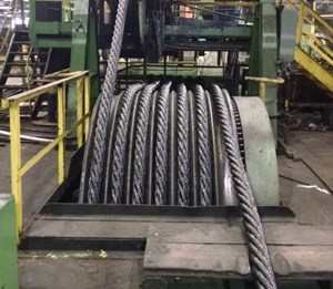
However, the most important part of all of this is the stranding process, and here is where my reactions turn from shock to awe. As a rigger using steel wire rope on a daily basis for slinging, I had often wondered how the rope was produced, and here it was before my eyes: The factory floor – acres of it – was full of lines of planetary stranders, all with sets of wires in large bobbins, as many as 64 wires on a single machine, feeding into a single, oily strand of rope. The factory had machines of all sizes hard at work, furiously spinning to produce the some 1200 different combinations of wire rope that come out of the factory every three months.
Finally, we come to the heart of the factory: We stand, astonished, gazing up at the 12 foot tall, 800 tonne closing machine, designed to produce the 7 inch rope for dragline boom pendants, and construction cable like that used to build the Brooklyn Bridge. The already huge strands are all dragged into a central point, slowly weaving the helical pattern of wires around a hefty centre rope into a single massive cable which will one day end up on a dragline somewhere in the world.
With a history spanning 120 years, the Wirerope Works factory has seen plenty of hard times, but it’s also had a lot of luck. With good leadership at the helm from the likes of Saltsgiver and Richards, and ongoing demand for steel wire rope, the old Williamsport factory could continue to produce its quality bespoke products for another 120 years.

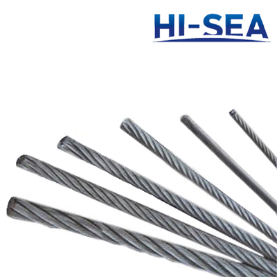
In stricter senses, the term wire rope refers to a diameter larger than 9.5 mm (3⁄8 in), with smaller gauges designated cable or cords.wrought iron wires were used, but today steel is the main material used for wire ropes.
Historically, wire rope evolved from wrought iron chains, which had a record of mechanical failure. While flaws in chain links or solid steel bars can lead to catastrophic failure, flaws in the wires making up a steel cable are less critical as the other wires easily take up the load. While friction between the individual wires and strands causes wear over the life of the rope, it also helps to compensate for minor failures in the short run.
Wire ropes were developed starting with mining hoist applications in the 1830s. Wire ropes are used dynamically for lifting and hoisting in cranes and elevators, and for transmission of mechanical power. Wire rope is also used to transmit force in mechanisms, such as a Bowden cable or the control surfaces of an airplane connected to levers and pedals in the cockpit. Only aircraft cables have WSC (wire strand core). Also, aircraft cables are available in smaller diameters than wire rope. For example, aircraft cables are available in 1.2 mm (3⁄64 in) diameter while most wire ropes begin at a 6.4 mm (1⁄4 in) diameter.suspension bridges or as guy wires to support towers. An aerial tramway relies on wire rope to support and move cargo overhead.
Modern wire rope was invented by the German mining engineer Wilhelm Albert in the years between 1831 and 1834 for use in mining in the Harz Mountains in Clausthal, Lower Saxony, Germany.chains, such as had been used before.
Wilhelm Albert"s first ropes consisted of three strands consisting of four wires each. In 1840, Scotsman Robert Stirling Newall improved the process further.John A. Roebling, starting in 1841suspension bridge building. Roebling introduced a number of innovations in the design, materials and manufacture of wire rope. Ever with an ear to technology developments in mining and railroading, Josiah White and Erskine Hazard, principal ownersLehigh Coal & Navigation Company (LC&N Co.) — as they had with the first blast furnaces in the Lehigh Valley — built a Wire Rope factory in Mauch Chunk,Pennsylvania in 1848, which provided lift cables for the Ashley Planes project, then the back track planes of the Summit Hill & Mauch Chunk Railroad, improving its attractiveness as a premier tourism destination, and vastly improving the throughput of the coal capacity since return of cars dropped from nearly four hours to less than 20 minutes. The decades were witness to a burgeoning increase in deep shaft mining in both Europe and North America as surface mineral deposits were exhausted and miners had to chase layers along inclined layers. The era was early in railroad development and steam engines lacked sufficient tractive effort to climb steep slopes, so incline plane railways were common. This pushed development of cable hoists rapidly in the United States as surface deposits in the Anthracite Coal Region north and south dove deeper every year, and even the rich deposits in the Panther Creek Valley required LC&N Co. to drive their first shafts into lower slopes beginning Lansford and its Schuylkill County twin-town Coaldale.
The German engineering firm of Adolf Bleichert & Co. was founded in 1874 and began to build bicable aerial tramways for mining in the Ruhr Valley. With important patents, and dozens of working systems in Europe, Bleichert dominated the global industry, later licensing its designs and manufacturing techniques to Trenton Iron Works, New Jersey, USA which built systems across America. Adolf Bleichert & Co. went on to build hundreds of aerial tramways around the world: from Alaska to Argentina, Australia and Spitsbergen. The Bleichert company also built hundreds of aerial tramways for both the Imperial German Army and the Wehrmacht.
In the last half of the 19th century, wire rope systems were used as a means of transmitting mechanical powercable cars. Wire rope systems cost one-tenth as much and had lower friction losses than line shafts. Because of these advantages, wire rope systems were used to transmit power for a distance of a few miles or kilometers.
Steel wires for wire ropes are normally made of non-alloy carbon steel with a carbon content of 0.4 to 0.95%. The very high strength of the rope wires enables wire ropes to support large tensile forces and to run over sheaves with relatively small diameters.
In the mostly used parallel lay strands, the lay length of all the wire layers is equal and the wires of any two superimposed layers are parallel, resulting in linear contact. The wire of the outer layer is supported by two wires of the inner layer. These wires are neighbors along the whole length of the strand. Parallel lay strands are made in one operation. The endurance of wire ropes with this kind of strand is always much greater than of those (seldom used) with cross lay strands. Parallel lay strands with two wire layers have the construction Filler, Seale or Warrington.
In principle, spiral ropes are round strands as they have an assembly of layers of wires laid helically over a centre with at least one layer of wires being laid in the opposite direction to that of the outer layer. Spiral ropes can be dimensioned in such a way that they are non-rotating which means that under tension the rope torque is nearly zero. The open spiral rope consists only of round wires. The half-locked coil rope and the full-locked coil rope always have a centre made of round wires. The locked coil ropes have one or more outer layers of profile wires. They have the advantage that their construction prevents the penetration of dirt and water to a greater extent and it also protects them from loss of lubricant. In addition, they have one further very important advantage as the ends of a broken outer wire cannot leave the rope if it has the proper dimensions.
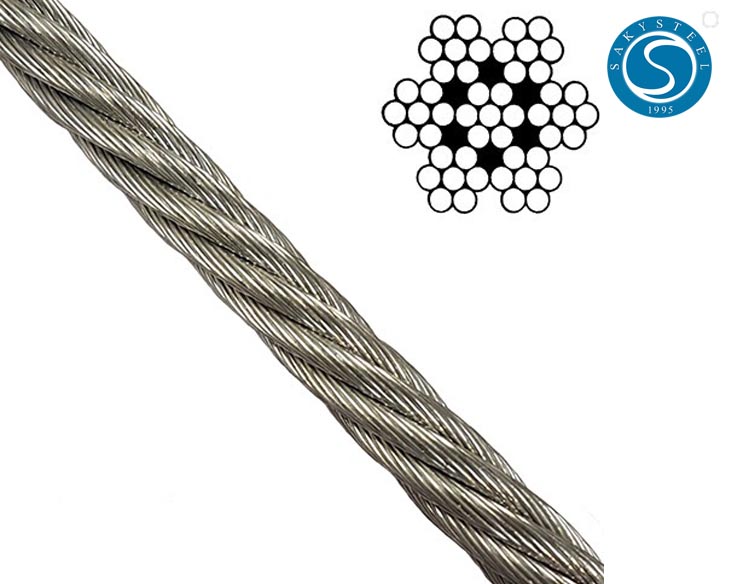
Stranded ropes are an assembly of several strands laid helically in one or more layers around a core. This core can be one of three types. The first is a fiber core, made up of synthetic material or natural fibers like sisal. Synthetic fibers are stronger and more uniform but cannot absorb much lubricant. Natural fibers can absorb up to 15% of their weight in lubricant and so protect the inner wires much better from corrosion than synthetic fibers do. Fiber cores are the most flexible and elastic, but have the downside of getting crushed easily. The second type, wire strand core, is made up of one additional strand of wire, and is typically used for suspension. The third type is independent wire rope core (IWRC), which is the most durable in all types of environments.ordinary lay rope if the lay direction of the wires in the outer strands is in the opposite direction to the lay of the outer strands themselves. If both the wires in the outer strands and the outer strands themselves have the same lay direction, the rope is called a lang lay rope (from Dutch langslag contrary to kruisslag,Regular lay means the individual wires were wrapped around the centers in one direction and the strands were wrapped around the core in the opposite direction.
Multi-strand ropes are all more or less resistant to rotation and have at least two layers of strands laid helically around a centre. The direction of the outer strands is opposite to that of the underlying strand layers. Ropes with three strand layers can be nearly non-rotating. Ropes with two strand layers are mostly only low-rotating.
Stationary ropes, stay ropes (spiral ropes, mostly full-locked) have to carry tensile forces and are therefore mainly loaded by static and fluctuating tensile stresses. Ropes used for suspension are often called cables.
Track ropes (full locked ropes) have to act as rails for the rollers of cabins or other loads in aerial ropeways and cable cranes. In contrast to running ropes, track ropes do not take on the curvature of the rollers. Under the roller force, a so-called free bending radius of the rope occurs. This radius increases (and the bending stresses decrease) with the tensile force and decreases with the roller force.
Wire rope slings (stranded ropes) are used to harness various kinds of goods. These slings are stressed by the tensile forces but first of all by bending stresses when bent over the more or less sharp edges of the goods.
Technical regulations apply to the design of rope drives for cranes, elevators, rope ways and mining installations. Factors that are considered in design include:
Donandt force (yielding tensile force for a given bending diameter ratio D/d) - strict limit. The nominal rope tensile force S must be smaller than the Donandt force SD1.
The wire ropes are stressed by fluctuating forces, by wear, by corrosion and in seldom cases by extreme forces. The rope life is finite and the safety is only ensured by inspection for the detection of wire breaks on a reference rope length, of cross-section loss, as well as other failures so that the wire rope can be replaced before a dangerous situation occurs. Installations should be designed to facilitate the inspection of the wire ropes.
Lifting installations for passenger transportation require that a combination of several methods should be used to prevent a car from plunging downwards. Elevators must have redundant bearing ropes and a safety gear. Ropeways and mine hoistings must be permanently supervised by a responsible manager and the rope must be inspected by a magnetic method capable of detecting inner wire breaks.
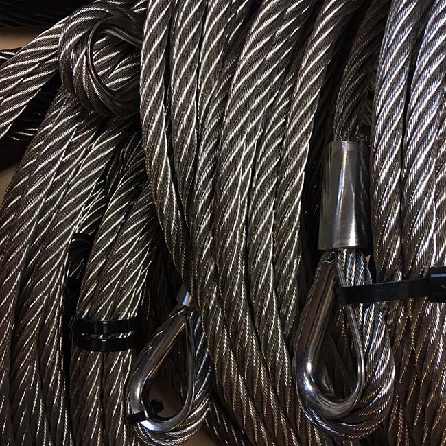
The end of a wire rope tends to fray readily, and cannot be easily connected to plant and equipment. There are different ways of securing the ends of wire ropes to prevent fraying. The common and useful type of end fitting for a wire rope is to turn the end back to form a loop. The loose end is then fixed back on the wire rope. Termination efficiencies vary from about 70% for a Flemish eye alone; to nearly 90% for a Flemish eye and splice; to 100% for potted ends and swagings.
When the wire rope is terminated with a loop, there is a risk that it will bend too tightly, especially when the loop is connected to a device that concentrates the load on a relatively small area. A thimble can be installed inside the loop to preserve the natural shape of the loop, and protect the cable from pinching and abrading on the inside of the loop. The use of thimbles in loops is industry best practice. The thimble prevents the load from coming into direct contact with the wires.
A wire rope clip, sometimes called a clamp, is used to fix the loose end of the loop back to the wire rope. It usually consists of a U-bolt, a forged saddle, and two nuts. The two layers of wire rope are placed in the U-bolt. The saddle is then fitted to the bolt over the ropes (the saddle includes two holes to fit to the U-bolt). The nuts secure the arrangement in place. Two or more clips are usually used to terminate a wire rope depending on the diameter. As many as eight may be needed for a 2 in (50.8 mm) diameter rope.
The mnemonic "never saddle a dead horse" means that when installing clips, the saddle portion of the assembly is placed on the load-bearing or "live" side, not on the non-load-bearing or "dead" side of the cable. This is to protect the live or stress-bearing end of the rope against crushing and abuse. The flat bearing seat and extended prongs of the body are designed to protect the rope and are always placed against the live end.
An eye splice may be used to terminate the loose end of a wire rope when forming a loop. The strands of the end of a wire rope are unwound a certain distance, then bent around so that the end of the unwrapped length forms an eye. The unwrapped strands are then plaited back into the wire rope, forming the loop, or an eye, called an eye splice.
A Flemish eye, or Dutch Splice, involves unwrapping three strands (the strands need to be next to each other, not alternates) of the wire and keeping them off to one side. The remaining strands are bent around, until the end of the wire meets the "V" where the unwrapping finished, to form the eye. The strands kept to one side are now re-wrapped by wrapping from the end of the wire back to the "V" of the eye. These strands are effectively rewrapped along the wire in the opposite direction to their original lay. When this type of rope splice is used specifically on wire rope, it is called a "Molly Hogan", and, by some, a "Dutch" eye instead of a "Flemish" eye.
Swaging is a method of wire rope termination that refers to the installation technique. The purpose of swaging wire rope fittings is to connect two wire rope ends together, or to otherwise terminate one end of wire rope to something else. A mechanical or hydraulic swager is used to compress and deform the fitting, creating a permanent connection. Threaded studs, ferrules, sockets, and sleeves are examples of different swaged terminations.
A wedge socket termination is useful when the fitting needs to be replaced frequently. For example, if the end of a wire rope is in a high-wear region, the rope may be periodically trimmed, requiring the termination hardware to be removed and reapplied. An example of this is on the ends of the drag ropes on a dragline. The end loop of the wire rope enters a tapered opening in the socket, wrapped around a separate component called the wedge. The arrangement is knocked in place, and load gradually eased onto the rope. As the load increases on the wire rope, the wedge become more secure, gripping the rope tighter.
Poured sockets are used to make a high strength, permanent termination; they are created by inserting the wire rope into the narrow end of a conical cavity which is oriented in-line with the intended direction of strain. The individual wires are splayed out inside the cone or "capel", and the cone is then filled with molten lead-antimony-tin (Pb80Sb15Sn5) solder or "white metal capping",zincpolyester resin compound.
Donald Sayenga. "Modern History of Wire Rope". History of the Atlantic Cable & Submarine Telegraphy (atlantic-cable.com). Archived from the original on 3 February 2014. Retrieved 9 April 2014.
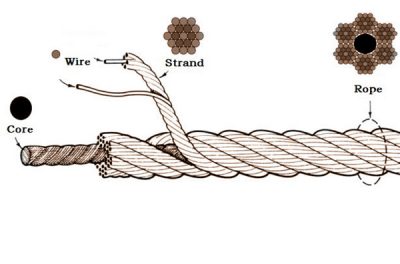
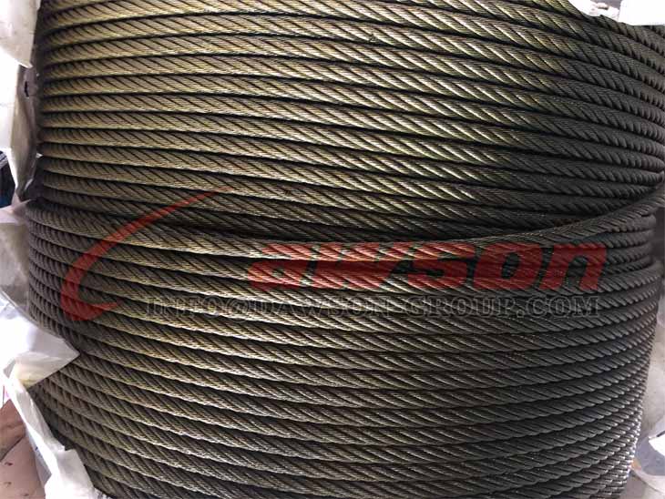
Wire ropes can be seen everywhere around us, they are made of strands or bundles of individual wires constructed around an independent core, suitable for construction, industrial, fitness, commercial, architectural, agricultural, and marine rigging applications.
Wire rod is made from high carbon steel wires(0.35 to 0.85 percent carbon) in a hot rolling process of a required diameter, usually from 5.5mm to 8 mm.
Wire rod is drawn to the required diameter by the 1st drawing machine after descaling dust and rust, adding mechanical properties suitable for application.
Positioning the wires different or the same size lay in multiple layers and same direction, or cross lay and diameter is maintained by one-third of the rope size.
So in theory, it is very simple to manufacture wire ropes. However there are many more details that must be closely monitored and controlled, and this requires time and experienced personnel since it is a super complicated project you cannot imagine.
It is the goal of LKS Wire Rope to provide manufactured rigging products and hardware which are competitively priced and delivered on time with zero defects at quality and service levels that are consistent with the expectations of our customers. We fully understand that to do so is good business. The success of LKS Wire Rope depends on our commitment to associate involvement, continual improvement, and improved business performance goals.
of good construction, sound material and adequate strength; (ii) properly maintained; (iii) thoroughly examined by a competent person at least once in every period of twelve months, and a register shall be kept containing the prescribed particularsofevery such examination; (bb) no such machinery shall be loaded beyond the safe working load which shall be plainly marked thereon; and (cc) while any person is employed or working on or near the wheel-tract of a travelling crane in any place wherehe would be liable to be struck by the crane, effective measures shall be taken to ensure that the crane does not approach within twenty feet of that place.
A Chinese finger provides a quick and fast means of (temporary) terminating different kinds of steel wire rope. The grips can be used for reeving and pulling of steel wire rope onto blocks or cranes. They are made from woven mesh galvanized steel wires leading to a very flexible and easy to handle termination
The technical scheme in the invention for solving the technical problem is: transparent shield and the soft skirt of protection all adopt the leaded protective material that can stop X ray to penetrate.Transparent shield is to go to the bottom to have the casing of an opening remainder sealing with rear wall junction surface place, this opening is the occupy-place mouth that passes in and out transparent shield for person under inspection, what match with occupy-place mouth has a transparent protective door, closes that transparent protective door makes it and transparent shield is common forms a safe space before film making.Antetheca bottom at transparent shield is provided with spiracle, and the lower bottom part of transparent shield is provided with primary and secondary band, and another sheet that primary and secondary band matches is fixed on the valut back side of the vertical position of X-ray production apparatus radiography stand, can form interlock with radiography stand by the link between primary and secondary band.Transparent shield and transparent protective door are arranged on the shielding support of energy load-bearing, and the two ends of shielding support are arranged on left and right pillar body middle and upper part.Protect soft skirt and adopt the folding material of leaded softness, the top of protecting soft skirt is fixed on protection skirt bracket, protects soft skirt and naturally droops both sides and crowd around backward and leave a passway for person under inspection"s turnover.Match with passway and be provided with soft plumbous door curtain, soft plumbous door curtain is arranged on protection skirt bracket.When use, close soft plumbous door curtain, jointly form a safe space by the soft skirt of protection, soft plumbous door curtain and metal chassis.Protection skirt bracket middle part is provided with a sub-master tape, and another corresponding sheet of primary and secondary band is fixed on the valut back side of the vertical position of X-ray production apparatus radiography stand, can form interlock with radiography stand by the link between primary and secondary band.The two ends of protection skirt bracket are arranged on left and right pillar body middle and lower part.Two column bodies are fixed on the right and left of metal chassis, and column body is made support body by column support frame, and column support frame is fastened on chassis by fastening bolt.On column support frame, erect two slide bar tracks are installed, the two ends up and down of slide bar track are fixed on column support frame by firm sleeve.The top of column support frame is provided with two fixed pulleys, on each fixed pulley, has steel wire rope to walk around.It is upper that one end of steel wire rope is fixed on corresponding counterweight stone roller, and the other end of two steel wire ropes is separately fixed at the end of corresponding shielding support and protection skirt bracket.The end of shielding support and protection skirt bracket is set on different slide bar tracks, and can slide up and down along slide bar track.Can regulate at any time the upper-lower position of transparent shield and the soft skirt of protection by sliding up and down of shielding support and protection skirt bracket, to adapt to the needs of each person under inspection"s height.When application, the valut of the vertical position of X-ray production apparatus radiography stand is placed in transparent shield and protects between soft skirt, person under inspection stand among the soft skirt of protection, is entered in transparent shield by part health more than shot region, and soft plumbous door curtain and transparent protective door are closed in adjusted position postpone.Now divide health to be placed in containing the soft skirt of lead protection the non-inspection portion of being taken pictures below position, the non-inspection portion of being taken pictures more than position is divided within health covers on leaded transparent shield, only the body part of being taken pictures is exposed to outside and accepts taking X-ray inspection, other parts of health have been avoided X-radiation damage.


 8613371530291