
steel wire rope terminations free sample
European foreword ................................................................................................................................................................ 4
5.3.2 Matching of ferrule to wire rope ...................................................................................................................... 11
A.2 Types of terminations.......................................................................................................................................... 16
A.3 Ropes for this design of ferrule ........................................................................................................................ 17
A.3.2 Rope types ................................................................................................................................................................ 17
A.3.4 Rope grade ............................................................................................................................................................... 17
A.3.5 Types of rope lay .................................................................................................................................................... 17
A.6 Matching wire rope to ferrule ........................................................................................................................... 21
Wire rope and cable are each considered a “machine”. The configuration and method of manufacture combined with the proper selection of material when designed for a specific purpose enables a wire rope or cable to transmit forces, motion and energy in some predetermined manner and to some desired end.
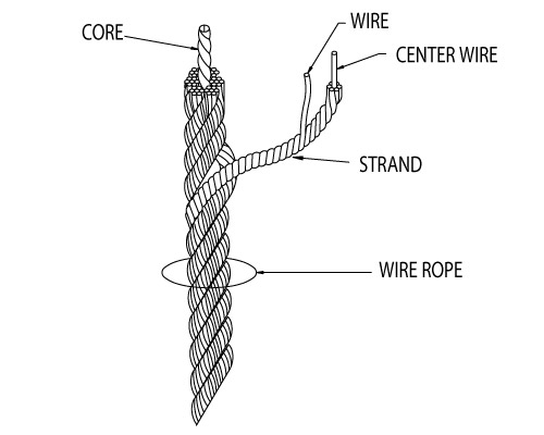
Two or more wires concentrically laid around a center wire is called a strand. It may consist of one or more layers. Typically, the number of wires in a strand is 7, 19 or 37. A group of strands laid around a core would be called a cable or wire rope. In terms of product designation, 7 strands with 19 wires in each strand would be a 7×19 cable: 7 strands with 7 wires in each strand would be a 7×7 cable.
Materials Different applications for wire rope present varying demands for strength, abrasion and corrosion resistance. In order to meet these requirements, wire rope is produced in a number of different materials.
Stainless Steel This is used where corrosion is a prime factor and the cost increase warrants its use. The 18% chromium, 8% nickel alloy known as type 302 is the most common grade accepted due to both corrosion resistance and high strength. Other types frequently used in wire rope are 304, 305, 316 and 321, each having its specific advantage over the other. Type 305 is used where non-magnetic properties are required, however, there is a slight loss of strength.
Galvanized Carbon Steel This is used where strength is a prime factor and corrosion resistance is not great enough to require the use of stainless steel. The lower cost is usually a consideration in the selection of galvanized carbon steel. Wires used in these wire ropes are individually coated with a layer of zinc which offers a good measure of protection from corrosive elements.
Cable Construction The greater the number of wires in a strand or cable of a given diameter, the more flexibility it has. A 1×7 or a 1×19 strand, having 7 and 19 wires respectively, is used principally as a fixed member, as a straight linkage, or where flexing is minimal.
Selecting Wire Rope When selecting a wire rope to give the best service, there are four requirements which should be given consideration. A proper choice is made by correctly estimating the relative importance of these requirements and selecting a rope which has the qualities best suited to withstand the effects of continued use. The rope should possess:Strength sufficient to take care of the maximum load that may be applied, with a proper safety factor.
Strength Wire rope in service is subjected to several kinds of stresses. The stresses most frequently encountered are direct tension, stress due to acceleration, stress due to sudden or shock loads, stress due to bending, and stress resulting from several forces acting at one time. For the most part, these stresses can be converted into terms of simple tension, and a rope of approximately the correct strength can be chosen. As the strength of a wire rope is determined by its, size, grade and construction, these three factors should be considered.
Safety Factors The safety factor is the ratio of the strength of the rope to the working load. A wire rope with a strength of 10,000 pounds and a total working load of 2,000 pounds would be operating with a safety factor of five.
It is not possible to set safety factors for the various types of wire rope using equipment, as this factor can vary with conditions on individual units of equipment.
The proper safety factor depends not only on the loads applied, but also on the speed of operation, shock load applied, the type of fittings used for securing the rope ends, the acceleration and deceleration, the length of rope, the number, size and location of sheaves and drums, the factors causing abrasion and corrosion and the facilities for inspection.
Fatigue Fatigue failure of the wires in a wire rope is the result of the propagation of small cracks under repeated applications of bending loads. It occurs when ropes operate over comparatively small sheaves or drums. The repeated bending of the individual wires, as the rope bends when passing over the sheaves or drums, and the straightening of the individual wires, as the rope leaves the sheaves or drums, causing fatigue. The effect of fatigue on wires is illustrated by bending a wire repeatedly back and forth until it breaks.
The best means of preventing early fatigue of wire ropes is to use sheaves and drums of adequate size. To increase the resistance to fatigue, a rope of more flexible construction should be used, as increased flexibility is secured through the use of smaller wires.
Abrasive Wear The ability of a wire rope to withstand abrasion is determined by the size, the carbon and manganese content, the heat treatment of the outer wires and the construction of the rope. The larger outer wires of the less flexible constructions are better able to withstand abrasion than the finer outer wires of the more flexible ropes. The higher carbon and manganese content and the heat treatment used in producing wire for the stronger ropes, make the higher grade ropes better able to withstand abrasive wear than the lower grade ropes.
Effects of Bending All wire ropes, except stationary ropes used as guys or supports, are subjected to bending around sheaves or drums. The service obtained from wire ropes is, to a large extent, dependent upon the proper choice and location of the sheaves and drums about which it operates.
A wire rope may be considered a machine in which the individual elements (wires and strands) slide upon each other when the rope is bent. Therefore, as a prerequisite to the satisfactory operation of wire rope over sheaves and drums, the rope must be properly lubricated.
Loss of strength due to bending is caused by the inability of the individual strands and wires to adjust themselves to their changed position when the rope is bent. Tests made by the National Institute of Standards and Technology show that the rope strength decreases in a marked degree as the sheave diameter grows smaller with respect to the diameter of the rope. The loss of strength due to bending wire ropes over the sheaves found in common use will not exceed 6% and will usually be about 4%.
The bending of a wire rope is accompanied by readjustment in the positions of the strands and wires and results in actual bending of the wires. Repetitive flexing of the wires develops bending loads which, even though well within the elastic limit of the wires, set up points of stress concentration.
The fatigue effect of bending appears in the form of small cracks in the wires at these over-stressed foci. These cracks propagate under repeated stress cycles, until the remaining sound metal is inadequate to withstand the bending load. This results in broken wires showing no apparent contraction of cross section.
Experience has established the fact that from the service view-point, a very definite relationship exists between the size of the individual outer wires of a wire rope and the size of the sheave or drum about which it operates. Sheaves and drums smaller than 200 times the diameter of the outer wires will cause permanent set in a heavily loaded rope. Good practice requires the use of sheaves and drums with diameters 800 times the diameter of the outer wires in the rope for heavily loaded fast-moving ropes.
It is impossible to give a definite minimum size of sheave or drum about which a wire rope will operate with satisfactory results, because of the other factors affecting the useful life of the rope. If the loads are light or the speed slow, smaller sheaves and drums can be used without causing early fatigue of the wires than if the loads are heavy or the speed is fast. Reverse bends, where a rope is bent in one direction and then in the opposite direction, cause excessive fatigue and should be avoided whenever possible. When a reverse bend is necessary larger sheaves are required than would be the case if the rope were bent in one direction only.
Stretch of Wire Rope The stretch of a wire rope under load is the result of two components: the structural stretch and the elastic stretch. Structural stretch of wire rope is caused by the lengthening of the rope lay, compression of the core and adjustment of the wires and strands to the load placed upon the wire rope. The elastic stretch is caused by elongation of the wires.
The structural stretch varies with the size of core, the lengths of lays and the construction of the rope. This stretch also varies with the loads imposed and the amount of bending to which the rope is subjected. For estimating this stretch the value of one-half percent, or .005 times the length of the rope under load, gives an approximate figure. If loads are light, one-quarter percent or .0025 times the rope length may be used. With heavy loads, this stretch may approach one percent, or .01 times the rope length.
The elastic stretch of a wire rope is directly proportional to the load and the length of rope under load, and inversely proportional to the metallic area and modulus of elasticity. This applies only to loads that do not exceed the elastic limit of a wire rope. The elastic limit of stainless steel wire rope is approximately 60% of its breaking strength and for galvanized ropes it is approximately 50%.
Preformed Wire Ropes Preformed ropes differ from the standard, or non-preformed ropes, in that the individual wires in the strands and the strands in the rope are preformed, or pre-shaped to their proper shape before they are assembled in the finished rope.
This, in turn, results in preformed wire ropes having the following characteristics:They can be cut without the seizings necessary to retain the rope structure of non-preformed ropes.
They are substantially free from liveliness and twisting tendencies. This makes installation and handling easier, and lessens the likelihood of damage to the rope from kinking or fouling. Preforming permits the more general use of Lang lay and wire core constructions.
Removal of internal stresses increase resistance to fatigue from bending. This results in increased service where ability to withstand bending is the important requirement. It also permits the use of ropes with larger outer wires, when increased wear resistance is desired.
Outer wires will wear thinner before breaking, and broken wire ends will not protrude from the rope to injure worker’s hands, to nick and distort adjacent wires, or to wear sheaves and drums. Because of the fact that broken wire ends do not porcupine, they are not as noticeable as they are in non-preformed ropes. This necessitates the use of greater care when inspecting worn preformed ropes, to determine their true condition.
Construction The size and number of wires in each strand, as well as the size and number of strands in the rope greatly affect the characteristics of the rope. In general, a large number of small-size wires and strands produce a flexible rope with good resistance to bending fatigue. The rope construction is also important for tensile load (static, live or shock) abrasive wear, crushing, corrosion and rotation. The number of strands and wires will influence the flexibility, fatigue and wear resistance of any given wire rope. Rope selection is often a compromise. Generally the more load bearing wires in the rope the greater the flexibility, however the smaller the wires the less abrasion resistance. For example, the same nominal diameter 7 x 7 wire would be less flexible than a 7 x 19 wire, hence a large number of small size wire and strands produce a flexible rope with good resistance to bending fatigue wear. The construction of wire rope is defined by the number of outer strands (first number), and the number of wires within that strand (second number) and then by the arrangement of the wires in each strand (shown in brackets). The wires in each strand can be arranged in several ways, for example a 6 x 19 construction the 19 wires in each strand are laid 9 around 9 around 1 centre wire.
Endurance Dyform 6 20-22// Usha Martin Crane Wire Rope 23-25// Wire Rope Slings Overview 26 // Tri-flex Wire Rope Slings 27 // Wire Rope Terminations 27 //
Core The core of a steel wire rope serves as a foundation for the strands, providing stability by keeping them in place throughout the life of the rope. Wire ropes can be supplied with either a fibre or wire core. Grade Wire rope can be manufactured in different steel grades, which directly affects the Minimum Breaking Force, (MBF). The higher the grade the higher the MBF. Common wire grades include: 1570, 1770, 1960 and 2070 Finish Wire Ropes can be supplied as Black (self-colour), Galvanised or Stainless Steel. Wire rope is lubricated at the time of manufacture, to help reduce friction between wires and strands, and the friction between the rope and drum or sheave. In addition, the lubrication retards corrosion and inhibits possible rotting of the fibre core.
RHOL Right Hand Ordinary Lay LHOL Left Hand Ordinary Lay RHLL Right Hand Lang’s Lay LHLL Left Hand Lang’s Lay Pref Preformed Post Postformed WRC Wire Rope Core WSC Wire Strand Core FC Fibre Core FW Filler Wire Strand Construction D or d Diameter (in millimetres)
Rotating or Non-Rotating Rotation resistant wire ropes are manufactured to resist rotation under load and are suitable for crane use and where long lengths are required.
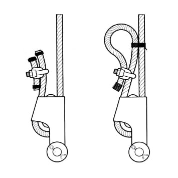
Clamping Wire Rope To ensure complete safety, it is imperative that wire ropes are clamped correctly. The diagrams below are a guide only. Please refer to the relevant Australian Standards AS 2076 for further information.
Correct Spooling of Steel Wire Rope on Drum It is imperative to correctly spool wire rope onto a drum. Improper spooling induces torque within the rope, which in turn reduces the life of the rope.
tension to avoid any slack on inner layers that can be crushed or nicked against the groove walls by outer layers. In general, the tighter the line, the better the spooling, but the rope should be tensioned with at least 2% of the breaking load or 10% of the working load.
Lubricating Steel Wire Ropes All steel wire ropes supplied by Robertsons are lubricated at the time of manufacture, however, periodic lubrication with good quality acid free and moisture free lubricant during use is required to ensure best performance. The following are accepted ways to lubricate wire ropes during use.
Steel Wire Rope Cutting Procedure Hand cutters for cutting ropes up to 8mm in diameter are sufficient. Mechanical or hydraulic cutters will be required for wire ropes with larger diameters.
Careless cutting can result in the balance of tension in the rope being destroyed. In every case, each side of the cut must be correctly seized to prevent strand
C: Both ends of the seizing wire are then pulled tight and twisted together for a length of one rope diameter. The twisted connection is then hammered into a strand valley.
Typical Steel Wire Rope Failures Steel wire rope is tough and durable, however eventually it will reach the end of its safe service life. Below are some examples of typical damage and deterioration. Steel wire ropes should be inspected every 12 months.
Storing Steel Wire Ropes Ensure steel wire rope is stored in a weather-proof storage space. If wire rope is to be kept unused for a considerable amount of time, it must be protected from the elements. The ideal storage area is a dry, well-ventilated building or shed. Avoid closed, unheated, tightly sealed buildings or enclosures because condensation will form when warm, moist outside (ambient) air envelopes the colder rope. Although wire rope is protected by a lubricant, this is not totally effective since condensation can still occur within the small sections between strands and wires, thereby causing corrosion problems. Ensure the reels are kept up off the ground, or are placed on a concrete floor. • Reels should be mounted on jacks or placed on a swift (with a brake arrangement) and care taken to see that the reel rotates as the rope unwinds • Ensure clearance for free rotation of the reel when the rope end is pulled and maintain continuous tension during haul off Correct Handling of Steel Wire Ropes Incorrect handling of steel wire ropes can cause kinking or loops Ropes should be stored in a clean dry place under cover. Reels or coils should be kept off the ground and supported by timber. They should also be examined periodically and rope dressing renewed as required. 1) Unreeling and Uncoiling Reels should be mounted on jacks and care taken to see that the reel rotates as the rope unwinds. Timber should be applied as a lever to one of the flanges to act as a brake, keeping the rope tight and preventing the reel from over- running. When the ropes are supplied in coils a turntalbe or swift should be employed and the free end pulled out with event tension as the swift, or turnatable revolve. Over-winding should be avoided at all times to obviate kinking. Coils may also be unwound by securing the free outside end of the rope and then rolling the coil along the ground; care being taken at all times to ensure that the coil is held firmly together, avoiding tight coils or kinks. Ropes should be stored in a clean dry place under cover. Reels or coils should be kept off the ground and supported by timber. They should also be examined periodically and rope dressing r newed as required. 1) Unreeling and Uncoiling Reels should be mounted on jacks and care taken to see that th reel ro ates as the rope unwinds. Timber should be applied as a lever t one of the flanges to act as a brake, keeping the rope tight and pr ve ting the reel from over- run ing. When the ropes are supplied in coils a turntalbe or swift should b employed and the fre end pulled out with vent tension as the swift, or turnatable revolve. Over-winding should be avoided t all times to obviate kinking. Coils may also be unwound by securing the free outside end of the rope and then rolling the coi along the ground; care being taken t all times to ensure that the coil is held firmly together, avoiding tight coils or kinks. Ropes should be stored in a clean ry lace under cove . R ls or coils shoul be k pt off the ground and supported by timber. They should also be examined periodically and rope dressing renewed as required. 1) Unreeling and Unc iling Re s should be mounted on jacks and c re taken to se that the reel r tates as the rope u winds. Timbe should be appl ed as a lever to one of the flanges to act as a brake, keeping the rope tight and preventing the reel from over- running. When the rope are supplied in coils a turntalbe or swift employed and the free end pulled out w th event tension as the swift, or tur atabl rev lve. Ov r-winding shoul be av ided at all t mes to obviate kinking. Coils may also be unwound by sec ing the fr e out id end of th rope and the rolling the c il along the ground; care being taken at all times to ensure that the coil is held firmly together, avoiding tight coils or kinks. Ropes should be stored in a clean dry place under cover. Reels or coils should be kept off the ground and supported by timber. They should also be examined periodically and rope dressing renewed a required. 1) Unreeling and Uncoiling Reels should be mounted on jacks and care taken to see that the reel rotates as the rope unwinds. Timber should be applied as a lever to one of the flanges to act as a brake, keeping the rope tight and preventing the reel from over- running. When the ropes are supplied in coils a turntalbe or swift should be employed and the free end pulled out with event tension as the swift, or turnatable revolve. Over-winding should be avoided at all times to obviate kinking. Coils may also be unwound by securing the free outside end of the rope and then rolling the coil along the ground; care being taken at all times to ensure that the coil is held firmly together, avoiding tight coils or kinks. Ropes should be stored in a clean dry place under cove . R els or coils should be k pt off the ground and supported by timber. They should also be xamined p riodically and rope dressing renewed as required. 1) Unreeling and U c iling Reels should be mounted on jacks and care taken to see that the reel tates as the rope u winds. Timb r should be appl ed as a lev r to ne of the flanges to act as a brake, keeping the rope tight and prev nti g the reel from over- running. When the rope are supplied in coils a turntalbe or swift empl y d and the free end pull d out with event tensi n as the swift, or t r at ble rev lve. Ov r-winding sh uld be avoided at all times to bviate kinki g. Coils may also be unwound by securing the free out id nd of the rop and then rollin the coil a ong the ground; care being taken at ll times to ensure that the coil is held firmly together, avoiding tight coils or kinks. forming in the steel wire rope, causing permanent damage. Below is a summary of the correct way to handle steel wire rope:
Although the steel wire rope is lubricated at the time of manufacture, a suitable lubricant should be applied every three months. The reels containing the steel wire ropes should also be rotated 90 degrees every three months.
11. Handling and Care of Wire Ropes 1. Handling and Care of Wire Ropes 11. Handling and Care of Wire Ropes 11. Handling and Care of Wire Ropes 1 . Handling and Care of Wire Rop s
2) Seizings It is important that before cutting ropes are properly seized with annealed mild steel wire or strand to avoid slack wires and possible rope distortion. 2) Se zings It s important that before cutting ropes are properly s ized with annealed mild steel wire or strand to avoid slack wires and possible rope distortion. 2) Seizings It is important that bef re cutting ropes are properly seized with annealed mild steel wire or strand to avoid slack wires and possible rope distortion. 2) Seizings It is important that before cutting ropes are properly seized with annealed mild steel wire or strand to avoid slack wires and possible rope distortion. 2) Seiz ngs It is important that before cutting ropes are properly seized with annealed mild steel wire or strand to avoid slack wires and possible rope distortion.
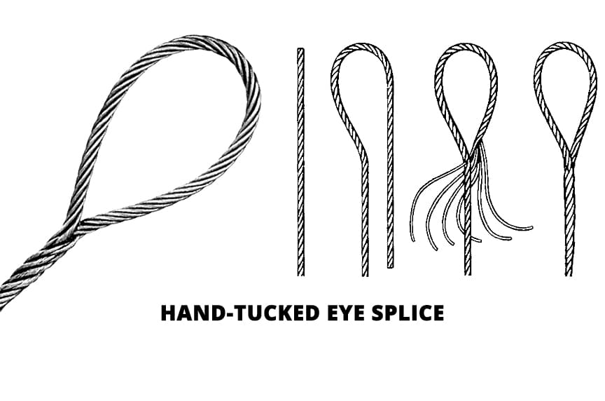
Wire Rope Terminations Hand spliced or machine swaged slings, with your choice of terminations, can be manufactured and tested (if required) on our premises at short notice. All slings and assemblies are permanently marked with safe working loads, based on a 5:1 factor of safety. Machine Swaging Aluminium Ferrules Sizes 2mm – 52mm. Copper Ferrules Sizes 2mm – 10mm Steel Ferrules Sizes 9mm – 75mm Swage Sockets Sizes 3mm – 52mm Hand Splicing from 2mm – 75mm dia
Galvanised Wire RHOL 63 41.8 Galvanised Wire RHOL 90 60.2 Galvanised Wire RHOL 107 70.7 Galvanised Wire RHOL 124 82 Galvanised Wire RHOL 161 107 Galvanised Wire RHOL 204 135 Galvanised Wire RHOL 252 167 Galvanised Wire RHOL 304 202 Galvanised Wire RHOL 363 241 Galvanised Wire RHOL 426 283 Galvanised Wire RHOL 493 328 Galvanised Wire RHOL 644 428 Galvanised Wire RHOL 816 542 Galvanised Wire RHOL 911 604 Galvanised Wire RHOL 1009 669 Galvanised Wire RHOL 1220 810 Galvanised Wire RHOL 1700 1110
Galvanised Wire RHOL 18.9 10.4 Galvanised Wire RHOL 27.2 14.3 Galvanised Wire RHOL 37.2 20.2 Galvanised Wire RHOL 47.5 25.66 Galvanised Wire RHOL 59.3 32 Galvanised Wire RHOL 73 39.4
POWERFORM® 8/8P • A high strength eight strand rope with plastic impregnated core ideal for situations where longer service life is required • High fatigue life resulting from the unique compaction process • Maximum resistance to crushing. Recommended for multi-layer spooling operations
• A sample of rope from each production batch is tested to destruction • Greater surface contact area resulting from the eight strand construction and compacted finish give longer rope life and reduced sheave wear • Optional plastic impregnation of the steel core. (P) signifies full plastic impregnation of the steel core.
POWERFORM® 35/35P • Superior strength and resistance to rotation • Suitable for use on single part and multi-part hoist reeving systems • High fatigue life due to unique compaction process • A sample of rope from each production batch is tested to destruction
52 2256.0 230.0 *Mass per unit length of POWERFORM 35P increases by approx. 3%. Note: • POWERFORM 35P is available on special request and prior confirmation. • Rope sizes and Breaking Force not shown in the standard table, may be available on request and prior confirmation.
Note: • POWERFORM 8P is available for rope diameter 16mm and above on special request and prior confirmation. • Rope sizes and Breaking Force not shown in the standard table, may be available on request and prior confirmation.
POWERFORM® 6/6P • A high strength rugged six strand rope ideal for situations where longer service life is required • Can be substituted for any six strand construction to improve service life • High fatigue life due to unique compaction process • A sample of rope from each production batch is tested to destruction
Typical Steel Wire Rope Sling Description Hand spliced or machine swaged slings, with your choice of terminations, can be manufactured and tested (if required) on our premises at short notice. All slings and assemblies are permanently marked with safe working loads, based on a 5:1 factor of safety.
Machine Swaging Aluminium Ferrules Sizes 2mm – 52mm Copper Ferrules Sizes 2mm – 10mm Steel Ferrules Sizes 9mm – 75mm Swage Sockets Sizes 3mm – 52mm Hand Splicing from 2mm – 75mm dia
*Mass per unit length of POWERFORM 6P increases by approx. 3%. Note: • POWERFORM 6P is available only for 16mm and above on special request and prior confirmation. • Rope sizes and Breaking Force not shown in the standard table, may be available on request and prior confirmation.


 8613371530291