
types of wire rope breaks in stock

Like all industrial equipment, aircraft cables and wire ropes wear while in service, and will require replacement. Though the cycle life of each cable varies based on construction and application, factors such as load and pulley condition can actually reduce this lifespan by triggering wire breaks. Not all wire breaks look the same, and understanding these differences can help detect issues in your system before they damage additional cables, or put human lives in danger. Here is a quick guide to help you understand where wire breaks occur (crowns vs. valleys), and three common examples of wire breaks (tension, fatigue, and abrasion).
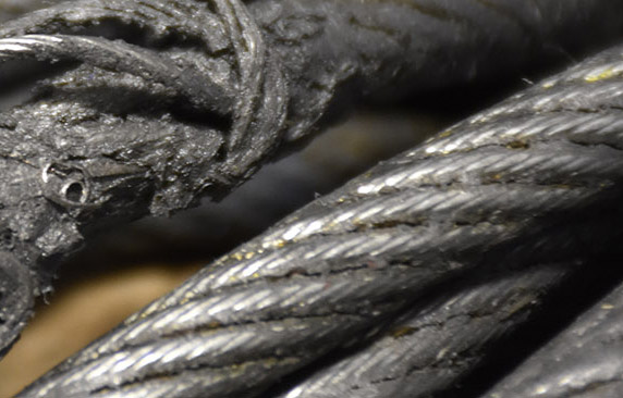
Wire breaks typically occur in two different locations on the outside of wire rope or aircraft cable. The first location is on the crowns of the strands, which are the highest points with the most surface area exposure. The second location is the valleys, or the spaces between the strands. Though crown breaks typically result from normal wear and tear, valley breaks are more suspicious and may indicate issues with the pulley system or wire rope itself.
Wires that have been worn to a knife-edge thinness are characteristic of abrasion breaks. Abrasion can occur from a number of different sources, but sheaves are the most common. Remember to check sheaves for signs of wear, damage, or deformity and replace as necessary.
If you notice one end of a broken wire is cupped, and the other end resembles a cone, your wire rope likely experienced a tension break. Tension breaks result from excessive loading, causing the wires to stretch beyond their limits until they snap. Once one wire break appears, others will continue to occur if the cable is not addressed.
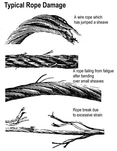
Fatigue damage is usually represented by zig-zag breaks with square ends. Like abrasion breaks, fatigue breaks can be triggered by a broad range of factors, including incorrect pulley size and excessive vibration. Check for worn pulleys and slack in the system to prevent issues from exacerbating.
Once you have replaced your damaged pulleys, or removed sharp obstructions in your system, begin your quote for brand new wire rope at https://strandcore.com/contact/. Our wire rope craftsmen can help you select the ideal wire rope for your application, and oftentimes provide a better solution for your existing setup. Browse our selection ofwire rope and aircraft cableonline, and do not hesitate to contact our sales team at sales@sanlo.com if you have any questions.

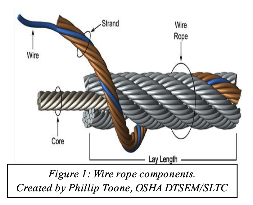
A finished wire rope is comprised of individual wires, make up individual strands, which are then laid in a helical pattern around a synthetic or steel core.
Wires are the smallest component of wire rope and they make up the individual strands in the rope. Wires can be made from a variety of metal materials including steel, iron, stainless steel, monel, and bronze. The wires can be manufactured in a variety of grades that relate to the strength, resistance to wear, fatigue resistance, corrosion resistance, and curve of the wire rope. Selecting the proper wire rope for your application is essential to long-lasting performance in a wire rope.
Strands of wire rope consist of two or more wires arranged and twisted in a specific arrangement. The individual strands are then laid in a helical pattern around the core of the rope. Strands made of larger diameter wires are more resistant to abrasion, while strands made of smaller diameter wires are more flexible.
The core of a wire rope runs through the center of the rope and supports the strands and helps to maintain their relative position under loading and bending stresses. Cores can be made from a number of different materials including natural or synthetic fibers and steel.
Lubrication is applied during the manufacturing process and penetrates all the way to the core. Wire rope lubrication has two primary benefits:Reduces friction as the individual wires and strands move over each other,
The following is a fairly comprehensive listing of critical inspection factors. It is not, however, presented as a substitute for an experienced inspector. It is rather a user’s guide to the accepted standards by which wire ropes must be judged. Use the outline to skip to specific sections:
Rope abrades when it moves through an abrasive medium or over drums and sheaves. Most standards require that rope is to be removed if the outer wire wear exceeds 1/3 of the original outer wire diameter. This is not easy to determine, and discovery relies upon the experience gained by the inspector in measuring wire diameters of discarded ropes.
All ropes will stretch when loads are initially applied. As a rope degrades from wear, fatigue, etc. (excluding accidental damage), continued application of a load of constant magnitude will produce incorrect varying amounts of rope stretch.
Initial stretch, during the early (beginning) period of rope service, caused by the rope adjustments to operating conditions (constructional stretch).
Following break-in, there is a long period—the greatest part of the rope’s service life—during which a slight increase in stretch takes place over an extended time. This results from normal wear, fatigue, etc.
Thereafter, the stretch occurs at a quicker rate. This means that the rope has reached the point of rapid degradation: a result of prolonged subjection to abrasive wear, fatigue, etc. This second upturn of the curve is a warning indicating that the rope should soon be removed.
In the past, whether or not a rope was allowed to remain in service depended to a great extent on the rope’s diameter at the time of inspection. Currently, this practice has undergone significant modification.
Previously, a decrease in the rope’s diameter was compared with published standards of minimum diameters. The amount of change in diameter is, of course, useful in assessing a rope’s condition. But, comparing this figure with a fixed set of values can be misleading.
These long accepted minimums are not, in themselves, of any serious significance since they do not take into account such factors as:Variations in compressibility between IWRC and fiber core
As a matter of fact, all ropes will show a significant reduction in diameter when a load is applied. Therefore, a rope manufactured close to its nominal size may, when it is subjected to loading, be reduced to a smaller diameter than that stipulated in the minimum diameter table. Yet under these circumstances, the rope would be declared unsafe although it may, in actuality, be safe.
As an example of the possible error at the other extreme, we can take the case of a rope manufactured near the upper limits of allowable size. If the diameter has reached a reduction to nominal or slightly below that, the tables would show this rope to be safe. But it should, perhaps, be removed.
Today, evaluations of the rope diameter are first predicated on a comparison of the original diameter—when new and subjected to a known load—with the current reading under like circumstances. Periodically, throughout the life of the rope, the actual diameter should be recorded when the rope is under equivalent loading and in the same operating section. This procedure, if followed carefully, reveals a common rope characteristic: after an initial reduction, the diameter soon stabilizes. Later, there will be a continuous, albeit small, decrease in diameter throughout its life.
Deciding whether or not a rope is safe is not always a simple matter. A number of different but interrelated conditions must be evaluated. It would be dangerously unwise for an inspector to declare a rope safe for continued service simply because its diameter had not reached the minimum arbitrarily established in a table if, at the same time, other observations lead to an opposite conclusion.
Because criteria for removal are varied, and because diameter, in itself, is a vague criterion, the table of minimum diameters has been deliberately omitted from this manual.
Corrosion, while difficult to evaluate, is a more serious cause of degradation than abrasion. Usually, it signifies a lack of lubrication. Corrosion will often occur internally before there is any visible external evidence on the rope surface.
Pitting of wires is a cause for immediate rope removal. Not only does it attack the metal wires, but it also prevents the rope’s component parts from moving smoothly as it is flexed. Usually, a slight discoloration because of rusting merely indicates a need for lubrication.
Severe rusting, on the other hand, leads to premature fatigue failures in the wires necessitating the rope’s immediate removal from service. When a rope shows more than one wire failure adjacent to a terminal fitting, it should be removed immediately. To retard corrosive deterioration, the rope should be kept well lubricated with a clear wire rope lube that can penetrate between strands. In situations where extreme corrosive action can occur, it may be necessary to use galvanized wire rope.
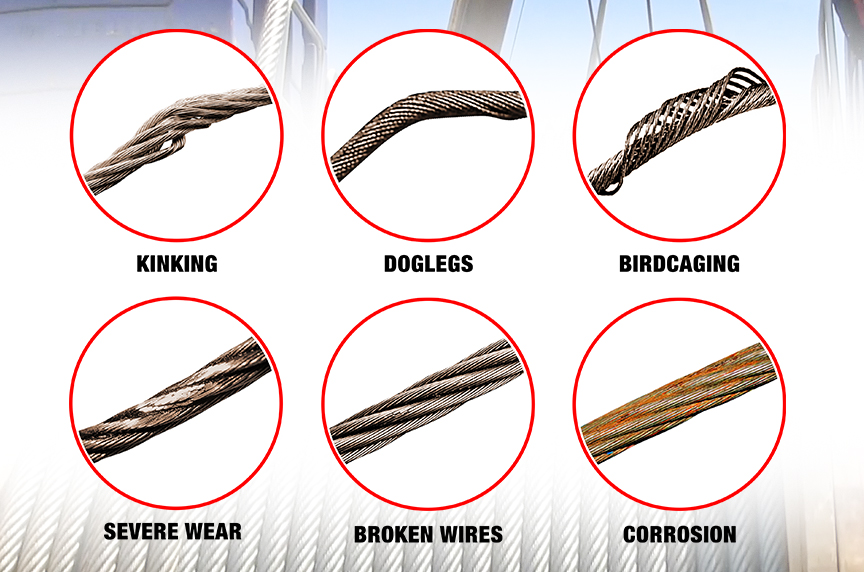
Kinks are tightened loops with permanent strand distortion that result from improper handling when a rope is being installed or while in service. A kink happens when a loop is permitted to form and then is pulled down tight, causing permanent distortion of the strands. The damage is irreparable and the sling must be taken out of service.
Doglegs are permanent bends caused by improper use or handling. If the dogleg is severe, the sling must be removed from service. If the dogleg is minor, exhibiting no strand distortion and cannot be observed when the sling is under tension, the area of the minor dogleg should be marked for observation and the sling can remain in service.
Bird caging results from torsional imbalance that comes about because of mistreatment, such as sudden stops, the rope being pulled through tight sheaves, or wound on too small a drum. This is cause for rope replacement unless the affected section can be removed.
Particular attention must be paid to wear at the equalizing sheaves. During normal operations, this wear is not visible. Excessive vibration or whip can cause abrasion and/or fatigue. Drum cross-over and flange point areas must be carefully evaluated. All end fittings, including splices, should be examined for worn or broken wires, loose or damaged strands, cracked fittings, worn or distorted thimbles and tucks of strands.
After a fire or the presence of elevated temperatures, there may be metal discoloration or an apparent loss of internal lubrication. Fiber core ropes are particularly vulnerable. Under these circumstances the rope should be replaced.
Cracked, bent or broken end fittings must be eliminated. The cause should be sought out and corrected. In the case of bent hooks, the throat openings—measured at the narrowest point—should not exceed 5%, not to exceed 1/4″ opening and any visibly apparent bend or twist from the plane of the unbent hook over normal nor should twisting be greater than 10°.
Continuous pounding is one of the causes of peening. This can happen when the rope strikes against an object, such as some structural part of the machine, or it beats against a roller or it hits itself. Often, this can be avoided by placing protectors between the rope and the object it is striking.
Another common cause of peening is continuous working-under high loads—over a sheave or drum. Where peening action cannot be controlled, it is necessary to have more frequent inspections and to be ready for earlier rope replacement.
Below are plain views and cross-sections show effects of abrasion and peening on wire rope. Note that a crack has formed as a result of heavy peening.
Scrubbing refers to the displacement of wires and strands as a result of rubbing against itself or another object. This, in turn, causes wear and displacement of wires and strands along one side of the rope. Corrective measures should be taken as soon as this condition is observed.
Wires that break with square ends and show little surface wear have usually failed as a result of fatigue. Such fractures can occur on the crown of the strands or in the valleys between the strands where adjacent strand contact exists. In almost all cases, these failures are related to bending stresses or vibration.
If diameter of the sheaves, rollers or drum cannot be increased, a more flexible rope should be used. But, if the rope in use is already of maximum flexibility, the only remaining course that will help prolong its service life is to move the rope through the system by cutting off the dead end. By moving the rope through the system, the fatigued sections are moved to less fatiguing areas of the reeving.
The number of broken wires on the outside of a wire rope are an index of its general condition, and whether or not it must be considered for replacement. Frequent inspection will help determine the elapsed time between breaks. Ropes should be replaced as soon as the wire breakage reaches the numbers given in the chart below. Such action must be taken without regard to the type of fracture.
* All ropes in the above applications—one outer wire broken at the point of contact with the core that has worked its way out of the rope structure and protrudes or loops out of the rope structure. Additional inspection of this section is required.
Rope that has either been in contact with a live power line or been used as “ground” in an electric welding circuit, will have wires that are fused, discolored and/or annealed and must be removed.
On occasion, a single wire will break shortly after installation. However, if no other wires break at that time, there is no need for concern. On the other hand, should more wires break, the cause should be carefully investigated.
On any application, valley breaks—where the wire fractures between strands—should be given serious attention. When two or more such fractures are found, the rope should be replaced immediately. (Note, however, that no valley breaks are permitted in elevator ropes.)
It is good to remember that once broken wires appear—in a rope operating under normal conditions—a good many more will show up within a relatively short period. Attempting to squeeze the last measure of service from a rope beyond the allowable number of broken wires (refer to table on the next page) will create an intolerably hazardous situation.
Recommended retirement criteria for all Rotation Resistant Ropes are 2 broken wires in 6 rope diameters or 4 broken wires in 30 rope diameters (i.e. 6 rope diameters for a 1″ diameter rope = 6″).
Distortion of Rotation Resistant Ropes, as shown below, can be caused by shock load / sudden load release and/or induced torque, and is the reason for immediate removal from service.
Wire Rope is an item often found on Wire Rope Cranes. Unfortunately, though these wires are not unbreakable and can/will succumb to the pressure of constant use and may potentially snap when in use. Which is why it is important to know what to look out for in an unsafe wire rope, the Government of Canada recommends a visual inspection of the wire before each use, but full inspections should be undertaken by a trained professional periodically. This article will cover what causes wire ropes to break, what your professional inspector will do to ensure your rope is safe and what you can look out for when completing your frequent inspection to ensure the rope is safe to work with.
When you hear the term wire rope you may picture in your mind a metal and seemingly unbreakable rope, and through wire ropes, can and will stand up better than many other rope types it is unfortunately not unbreakable. Some things that can cause a wire rope to break include:
Kinks caused by improper installation of a rope, sudden release of a load or knots that were made to shorten a rope can cause the rope to become compromised
Many of these causes can be minimized by the use of proper crane design and rope maintenance procedures, most of these causes though are unavoidable and are considered to be part of a normal rope life. The two main causes that are considered unavoidable are crushing and internal and external fatigue.
Many wire ropes are subject to a lot of repetitive bending over a sheave, which causes the wire to develop cracks in its individual wires. These broken wires often develop in the sections that move over sheaves. This process will become escalated if a rope travels on and off of a grooved single layer drum, which causes this to go through a bending cycle. Tests in the past have shown that winding on a single layer drum is equal to bending over a sheave because it causes similar damage.
Fatigue breaks often develop in segments as stated before these segments are usually the part of the rope surface that comes into direct contact with a sheave or drum. Because this is caused by external elements rubbing, oftentimes these breakages are external and visible for the eye to see. Once broken wires start to appear, it creates a domino effect and quickly much more will appear. Square ends of wires are common for fatigue breaks. These breaks are considered a long-term condition and are to be considered part of the normal to the operating process.
Internal Breaks,these breaks can develop over time-based upon the loading of the hoist. Many ropes are made of a torque-balanced multi-strand design, which comprises of two or more layers of strands. A torque balance is created in multi-strand ropes, by layering the outside and inside ropes in opposite directions. Multi-strand ropes offer much more flexibility and have a more wear-resistant profile. Though the wires in these ropes touch locally and at an angle, which causes them to be subject to both the effect of radial load, relative motion between wires and bending stresses when bent on sheaves or drums.
Nicking and fatigue patterns such as the ones discussed before occur in Independent Wire Rope Cores or IWRC ropes. IWRC ropes have outer wires of the outer strands, which have a larger diameter than the outer core strands. This helps to minimize inner strand nicking between the outer strands of the IWRC. The outer strands and the IWRC strands are approximately parallel. Often their neighbouring strands support these outer strands while the outer IWRC wires are relatively unsupported.
With these geometrical features it allows for the wire to fluctuate under tensile loads, the outer IWRC wires are continuously forced into valleys in between the outer strand wires and then released. This system results in secondary bending stresses which leads to a large number of core wires with fatigue breaks. These breaks are often close together and form in groups. This eventually leads to the IWRC breaking or completely disintegrating into short pieces of wire that lay, half a length long. This condition is often called complete rope core failure.
It is as the IWRC fails, and the outer strands lose their radial support then valley breaksform. Valley breaks occur when the outer strand wires bear against each other tangentially. This results in interstrand nicking, which restricts the movement of strands within the rope; without the freedom to move, secondary fatigue breaks occur in the outer strands, which will develop a stand tangent points. These breaks occur in the valleys between the outer strands hence why they are called valley breaks.
So to go over what we just learned, internal broken wires occur often in ropes that are operated with large diameter sheaves and high factors of safety. These breakages can occur when a reeving system incorporates sheaves lined with plastic or all plastic sheaves; these sheave units offer more elastic support than their steel counterparts. Which causes the pressure between outer wires and sheave grooves to be reduced to the point where the first wire breaks will occur internally.
If a section of a rope travels on and off of a grooved multi-layer drum, then it goes through what is called a bending cycle. The bending cycle occurs by a section of rope spooling in the first layer and is bent around the smooth drum surface, but when the second layer rolls around the rope section in the first layer will be spooled over. This causes the first layer to become compressed and damaged on the upper side by the second rope layer. With continued spooling the rope layers in the second and higher layers will, in turn, be damaged on both sides during contact with their neighbouring rope layers. This damage is caused both by the compression of the rope and by the rope laying on a rough surface.
Accelerated wear occurs where the point of the rope is squeezed between the drum flange and the previous layer. Often times the slap of rope at the crossover points causes peening, martensitic embrittlement and/or wire plucking, further associated rope damage is caused when the rope crosses over from layer to layer on a drum.
Also, if the lower wire rope areas where not spooled under sufficiently high tension the lower wraps can become displaced by the additional rope sections which would allow for these new rope sections to slide down in between them, which will lead to severe rope damage.
Many regulators have decided that the Statutory Life Policy be overly wasteful and they tend to use the Retirement for Clause Policy. A wire rope deteriorates slowly over its entire service, but to be aware of the state of deterioration, a wire rope must be periodically inspected. Moderate deterioration is normally present, and low levels of deterioration do not justify retirement. Which is why you have wire rope inspections to monitor the normal process of deterioration. This ensures that the rope can be retired before it can become dangerous. Besides, these inspections can detect unexpected damage or corrosion on the wire rope which will allow you to take corrective actions to ensure the longevity of the wire rope.
This system is useful for detecting external rope deterioration. To use this approach, the inspector will lightly grab the rope with a rag. The inspector then glides the cloth over the rope. Often times external broken wires will porcupine (stick up). When the rope moves along the wire it will be snagged on the broken wire. The inspectorwill then stops dragging the cloth along the wire and visually inspects the condition of the wire.
Frequently broken wires often do no porcupine, which is why a different test procedure must be utilized. This test involves moving along the rope two or three feet at a time and visually examining the rope. This method though can become tiresome because oftentimes the rope is covered in grease and many internal and external defects will avoid detection through this method.
Another method involves measuring the wire ropes diameter. This involves comparing the diameter of the current rope to the original rope’s diameter. Changes in the diameter of the rope indicate external and/or internal rope damage. This method is not perfect because many different wire breakages damages do not change the diameter of the rope.
You can also check for several visible signs of distributed losses of the metallic cross-sectional area. This is often caused by corrosion, abrasion and wear. To internally check for damage, you can insert a marlinspike under two strands and rotate it to lift the strands and open the rope.
Visual inspections are often not well suited for the detection of internal rope damage. This means that they have limited value as the only means of wire rope inspection. Though visual inspections do not require special machines. When completed by a knowledgeable and experienced rope examiner through visual inspections can be valuable tools for evaluating rope degeneration.
Electromagnetic Inspections or EM gives a detailed insight into the exact condition of a rope. EM is a very reliable inspection method and is a universally accepted method for inspecting wire ropes for mining, ski lifts and other similar industries. There are two distinct EM inspection methods, which have been developed to classify defects called Localized-Flaw (LF Inspection) and Loss-of-Metallic-Area Inspection (LMA Inspection type)
LF Inspection is similar to the rag-and-visual method. This inspection method is suited primarily for finding localized flaws, such as broken wires. Which is why small hand-held LF instruments are called electronic rags.
Electromagnetic and visual wire rope inspection methods are like peanut butter and jelly or cookies and milk they are the perfect combination, and both are essential for safe rope operation. Which is why both methods are often used to ensure maximum safety.
A program that involves periodic inspections is extremely effective. To establish baseline data for future inspections, a wire rope inspection program should begin with an initial inspection after a break-in period. Then the inspections should follow at scheduled intervals, with documentation of the ropes deterioration over its entire service life.
For multi-strand ropes often times visual inspections are ineffective which is why statutory life policy for a ropes retirement is often adopted. This means that these ropes are often discarded long before they should be meaning millions of dollars’ worth of perfectly good wire ropes are being thrown away annually.
Some people have suggested that non-rotating ropes should not be used if cranes use a single layer winding on a drum. Following this line of thought, this would mean multi-strand ropes should be used only when winding on multi-layer drums. This would cause wires to break the surface faster than internal wire damage can occur, these non-rotating wire ropes will be replaced long before internal fatigue can set in.
When internal broken wires are the problem electromagnetic rope testing can be the solution. Though there are some factors one needs to take into account such as certain regulations require rope retirement when a certain number of broken wires per unit of rope length exceed a set limit. This discard number that is specified in retirement standards refers solely to external wire breaks. This means the condition of a wire rope with internal breaks is therefore left up to the inspector.
Though you also need to take into account detailed detection and quantitative characterization of internal broken wires in ropes with many breaks and cluster breaks could be a problem. These difficulties are caused by the fact that electromagnetic wire rope can be influenced by several parameters such as:
Clusters of broken wires can cause an additional problem because the relative position of broken wires concerning each other within the rope is not known
Broken wires with zero or tight gap widths are not detectable by electromagnetic inspection because they do not have a sufficient magnetic leakage flux.
When you consider all of this you can quickly realize that you can only estimate the number of broken wires that have formed on a wire rope. You can use the LF trace for the detection of broken wires, though unfortunately it is not quantitative so it cannot be used to estimate the number of broken wires. Though it is good to note that if any internal broken wires are present an LMA trace will show rapid relatively small variations of a cross-section.
An electromagnetic inspection will help to enhance the accuracy and reliability of the inspection, by combining visual and EM methods they will be able to detect deterioration at the earliest stages. The inspections can be then used as an effective preventive maintenance tool. For example, the inspector early on detects corrosion, and you immediately apply the corrective action of improving the lubrication of the wire rope.
Wire ropes should be inspected by a certified inspector when installing it, and periodically throughout its life cycle. A wire rope should go through a quick, but thorough inspection every day that you use it at the beginning and end of each shift and you should keep records of all inspections. Ensure that your certified wire rope inspector uses a combination of visual inspection methods and electromagnetic inspection methods because this will ensure the optimum safety and longevity of the rope. This is especially true for ropes that are more likely to develop internal broken wires, and inspections completed by a certified inspector is the best way of having a preventive maintenance program and extending the life of your wire rope.
Queensland Division of Workplace Health and Safety, “Non-rotating hoist wire ropes, multi fall configurations, Health and Safety Alert,” http://www.whs.qld.gov.au/alerts/97-i-5.pdf
Verreet, R. “Wire rope damage due to bending fatigue and drum crushing,” O.I.P.E.E.C.(International Organization for the Study of the Endurance of Wire Rope) Bulletin 85, June 2003, Reading (UK), ODN 0738, pp. 27-46.
Easy-to-read, question-and-answer fact sheets covering a wide range of workplace health and safety topics, from hazards to diseases to ergonomics to workplace promotion. MORE ABOUT >
Maintain a record for each rope that includes the date of inspection, type of inspection, the name of the person who performed the inspection, and inspection results.
Use the "rag-and-visual" method to check for external damage. Grab the rope lightly and with a rag or cotton cloth, move the rag slowly along the wire. Broken wires will often "porcupine" (stick out) and these broken wires will snag on the rag. If the cloth catches, stop and visually assess the rope. It is also important to visually inspect the wire (without a rag). Some wire breaks will not porcupine.
Measure the rope diameter. Compare the rope diameter measurements with the original diameter. If the measurements are different, this change indicates external and/or internal rope damage.
Visually check for abrasions, corrosion, pitting, and lubrication inside the rope. Insert a marlin spike beneath two strands and rotate to lift strands and open rope.
Assess the condition of the rope at the section showing the most wear. Discard a wire rope if you find any of the following conditions:In running ropes (wound on drums or passed over sheaves), 6 or more broken wires in one rope lay length; 3 or more broken wires in one strand in one rope lay. (One rope lay is the distance necessary to complete one turn of the strand around the diameter of the rope.)
Corrosion from lack of lubrication and exposure to heat or moisture (e.g., wire rope shows signs of pitting). A fibre core rope will dry out and break at temperatures above 120°C (250°F).
Kinks from the improper installation of new rope, the sudden release of a load or knots made to shorten a rope. A kink cannot be removed without creating a weak section. Discarding kinked rope is best.
Although every effort is made to ensure the accuracy, currency and completeness of the information, CCOHS does not guarantee, warrant, represent or undertake that the information provided is correct, accurate or current. CCOHS is not liable for any loss, claim, or demand arising directly or indirectly from any use or reliance upon the information.
Even though wire ropes are strong and reliable does not mean they are unbreakable. They can break or damage due to constant pressure or overuse. When using wire ropes you want to make sure to check them daily for damage and wear.
You can avoid the above problems by practicing proper rope maintenance procedures. On the other hand, some issues cannot be avoided so frequent inspections and checks should be done to ensure the wire rope is safe for use.
If you are worried about the conditions of your wire rope, you can implement a statutory life policy. This states that your ropes are to be retired at predetermined dates. Or you can do a retirement clause – which will allow you to use cables until they have deteriorated beyond a certain point.
Don’t wait until your wire ropes are damaged and broken, keep up with the health of your ropes! If you think you’re due for new wire ropes or an inspection, call the experts atSilver State Wire Rope and Rigging! We have a reputation for our high-quality, well-informed solutions, efficiency, and professionalism.Call usfor all your wire rope needs!
Industrial machines generally have heavy loads to lift and pull. Whether it’s excavators or farm machinery, wire rope is the rope that is used. Industrial wire ropes typically range from 3/8” (9.5mm) to 2-1/2” (63.5mm) in diameter, and besides heavy machining applications, wire ropes also serve as support cables for large static structures such as stadium roofs and bridges. Manufacturing a wire rope begins with steel wire that is anywhere from .6 to 8 millimeters in diameter. The first step is to wind several of these wires together, into a strand. How many wires per strand depends on the application of the wire. Different applications require various levels of flexibility and strength.
Steel wires are used for wire ropes and are typically fashioned from a non-alloy carbon steel material. This metal has a carbon content of 0.5 to 0.95%, which makes it incredibly strong. As a result of its strength and durability, steel wires are able to support large tensile forces and can run over sheaves with small diameters.
Strands are created when wires of different layers cross each other. Parallel lay strands are some of the most commonly manufactured strands. The lay length of the wire strands is generally equal to the wires of any two layers that are parallel. This means that there is linear contact. Inner layer wires support the outer layer wires along the entire length of the strand.
In essence, spiral ropes are round strands that are assembled in layers of wires that are aligned in a spiral design. Spiral ropes are constructed so that they are non-rotating, which means that that there is practically no tension under the rope torque.
Stranded ropes are comprised of several different layers of strand that are laid in multiple spiraling layers around a core. A stranded rope core can come in three different types: fiber cores, wire strand cores, or independent wire rope cores. Fiber cores are the most flexible and elastic of the 3 variations, but are easily crushed. Wire strand cores are typically used for suspension and have a high tensile strength. Independent wire rope is the most durable in all types of environments.
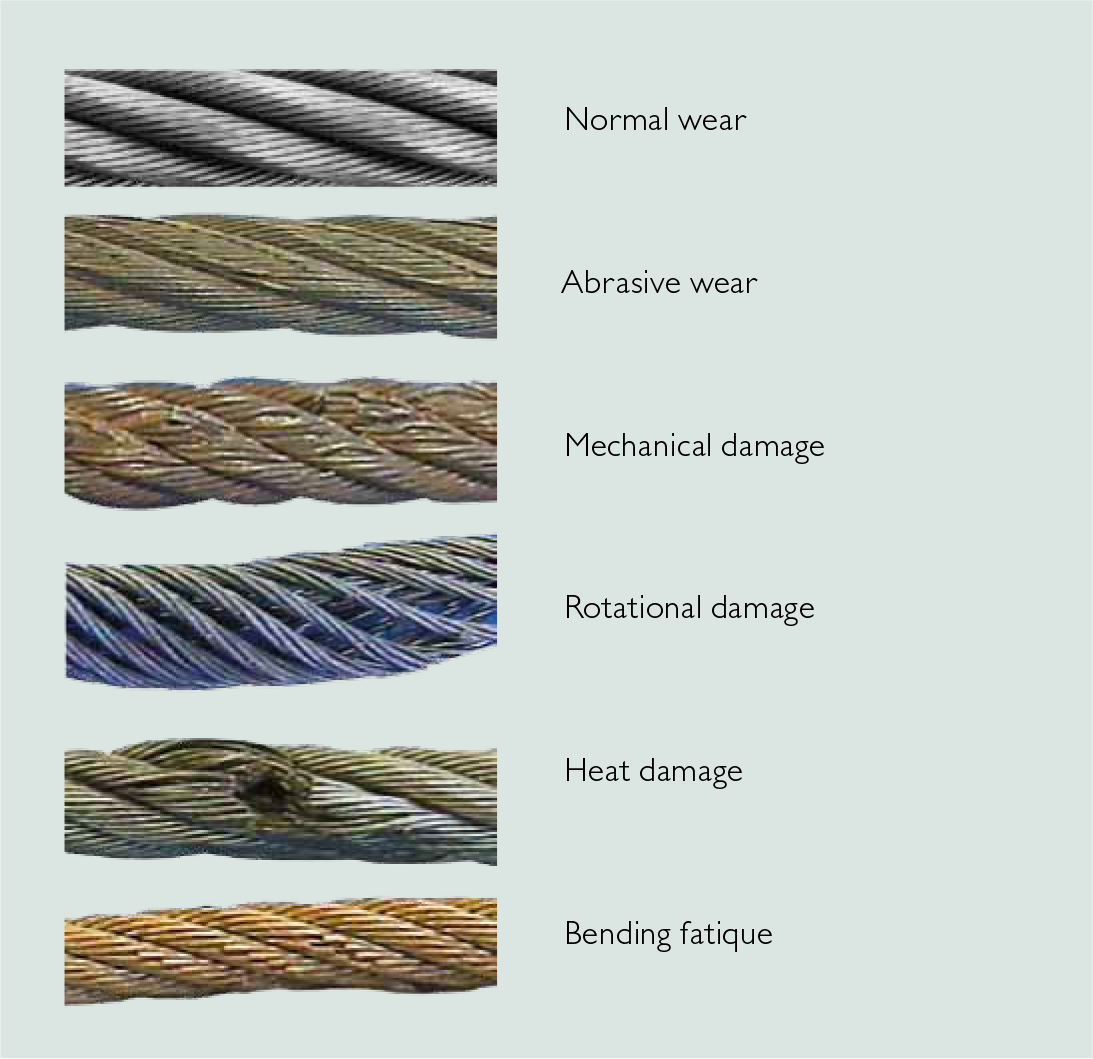
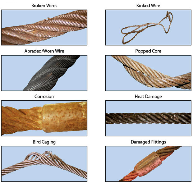
Wire breakshowsone end of broken wire coned, the other cupped. Necking down of the broken ends is typical of this type of break.Where tension breaks are found, the rope has been subjected to overloading, either for its original strength (new rope) or for its remaining strength in the case of a used rope. Tension breaks frequently are caused by the sudden application of a load to a slack rope, thereby setting up incalculable impact stresses.
Wire break shows broken ends worn to a knife-edge thinness.Abrasive wear obviously is concentrated at points where the rope contacts an abrasive medium, such as the grooves of sheaves and drums, or other objects with which the rope comes into contact. Unwarranted abrasive wear indicates improperly grooved sheaves and drums, incorrect fleet angle, or other localized abrasive conditions.
Wire breaksareusually transverse orsquareshowinggranularstructure.Oftenthese breaks will develop a shattered orjagged fracture, depending on the type ofoperation.Where fatigue breaks occur, the rope has been bent repeatedly around too small a radius. Whipping, vibration, slapping and torsional stresses also will cause fatigue. Fatigue breaks are accelerated by abrasion and nicking.
Easily noted by the wire"s pitted surface, wire breaks usually show evidence of tension, abrasion and/or fatigue.Corrosion usually indicates improper lubrication. The extent of the damage to the interior of the rope is extremely difficult to determine; consequently, corrosion is one of the most dangerous causes of rope deterioration.
Wirewill be pinched down and cut atbroken ends, or will show evidence of ashear-like cut.This condition is evidence of mechanical abuse caused by agents outside the installation, or by something abnormal on the installation itself, such as a broken flange.
Hoisting loads with a wire rope is a simple operation. Hook it up; lift it. Turns out, it’s more complicated than it appears. The details of setting up, inspecting, and maintaining lifts with wire ropes are not complicated, but are critical. A lift that goes awry is dangerous. A bad lift puts workers at risk. In this article, we discuss the causes of wire rope failure and how to avoid them.
Abrasion breaks are caused by external factors such as coming into contact with improperly grooved sheaves and drums. Or just hitting against some object during operation. Worn, broken wire ends is the result of an abrasion break. Common causes of abrasion breaks include:
Core slippage or protrusion is caused by shock load or improper installation of the wire rope. Excessive torque can cause core slippage that forces the outer strands to shorten. The core will then protrude from the rope. Wire ropes designed to be rotation-resistant should be handled carefully so as not to disturb its lay length.
Corrosion breaks cause pitting on the individual wires that comprise the rope. This type of damage is caused by poor lubrication. However, corrosion breaks are also caused by the wire rope coming into contact with corrosive chemicals, such as acid.
There are many ways the strands of a rope can be crushed or flattened. Improper installation is a common cause. To avoid crushing, you’ll want the first layer of the wire rope to be very tight. You’ll also need to properly break-in a new wire rope. Other causes of crushing include cross winding, using a rope of the wrong diameter, or one that it too long.
Cracks to individual wires are caused by fatigue breaks. Fatigue breaks happen because the wire rope is being bent over the sheave over and over again. In time, the constant rubbing of the wire rope against the sheave or drum causes these breaks. Sheaves that are too small will accelerate fatigue breaks because they require more bending. Worn bearings and misaligned sheaves can also cause fatigue. A certain number of broken wires is acceptable. The worker responsible for equipment inspection prior to use should know the American Society of Mechanical Engineers (ASME) standard for wire ropes. The ASME standard determines whether the wire rope must be replaced. (https://www.asme.org/)
Selecting the right wire rope for the job is critical. There is never a perfect rope. For example, you will need to make a tradeoff between fatigue resistance and abrasion resistance. There are several aspects to wire rope design to consider, including:
In general, the proper wire rope will have a strength rating high enough to handle the load. (Strength is rated in tons.) It can handle the stress of repeated bending as it passes over sheaves or around drums. How you attach the rope in preparation for the lift matters and should only be handled by properly trained workers.
The wire rope (and all the equipment involved in a lift) should be fully inspected prior to the lift. The worker performing the inspection should be well-versed in the types of damage that can cause a wire rope to fail. Using a checklist is highly recommended. This will ensure that the inspection is complete. Worker and supervisor signoff will increase accountability. Of course, the wire rope must be maintained according to the manufacturer’s instructions.
How a wire rope is stored, the weather conditions in which it is used, and how they are cleaned all affect its useful life. The Occupational Safety and Health Administration (OSHA) provides these recommendations: (Source: https://www.osha.gov/dsg/guidance/slings/wire.html)
For a choker hitch, the choke points should only be on the sling body and not on a fitting. Also, reduce the rated load when an angle of a choke is under 120 degrees.
Preventing wire rope failures starts with selecting the right one for the job. When in doubt, talk with your local equipment dealer. Be prepared to discuss your specific job requirements. A thorough inspection of the wire rope prior to using it is critical. Finally, properly store your wire rope. The selection, inspection, and care of wire rope is key to job safety.
Your crane"s wire rope works hard. (Almost as hard as you do.) It can deteriorate more quickly than you might think, posing a real danger for you and your crew. In this article, we"ll answer the following questions.
Before we get into that, let"s take a brief moment to go over the proper wire terminology. Understanding the make-up of the wire rope allows you to have a clear understanding of when the rope needs to be replaced.
Flexible steel wire rope is made up of individual wires that make up a strand; these strands are then wrapped around a central core to make up a rope.
Understanding the difference between a wire and a strand is critical. If a strand (grouping of wires) in the rope breaks, the crane wire would need to be replaced. However, if a single wire in the strand breaks, the rope itself may still be usable.
Rag & Visual Inspections: In this method, you use a rag in your inspection, pulling it slowly across the strand, stopping for a closer and more detailed inspection wherever the rag gets caught on a wire.
The Diameter Measurement Method: This method involves comparing the diameter of your rope at various intervals with the rope"s official diameter per the manufacturer"s guidelines. A variation in the rope"s diameter can alert you to potential interior damage that a visual inspection would miss.
Localized Flaw Inspections (LF) vs. Loss of Metallic Area Inspections (LMA) - Both methods use electromagnetics to search for a wire rope"s internal damage.
According to OSHA"s safety regulations, you"re required to inspect your crane"s wire ropes at least every 12 months by qualified professionals. However, OSHA and other experts also recommend inspecting your wire ropes more frequently, such as after every initial installation or repair, or daily before each shift to ensure a safe work environment.
As discussed at the very beginning of this article, we can break down wire rope into three parts. First, wires, which make up strands, and then the strands wrapped around the central core make the rope. Of your total number of wires, you never want more than 10% to be damaged before you need to look into crane wire rope replacement.
According to OSHA, only "trained personnel should carry out inspections," and according to the Crane Manufacturers Association of America, a certified crane inspector should get 2,000+ hours of field experience and training.
We at Americrane & Hoist Corporation are just the experts you need, qualified to offer OSHA inspections and provide operator safety training classes to your employees. Contact us today!
Information about wire rope unloading, storage, handling, installation, operation, lubrication, inspection, maintenance and possible causes for rope faults is given in this article to get best service from it.
Whenever handling wire rope, take care not to drop reels or coils. This can damage wire rope and collapse the reel, making removal of the wire rope extremely difficult. Rope in a coil is unprotected and may be seriously damaged by dropping.
Wire ropes should be stored in a well ventilated, dry building or shed and shall not be in contact with the floor. If it is necessary to store them outside, cover them so that moisture cannot induce corrosion. The place should be free from dust, moisture and chemical fumes. To protect the wooden reels from the attack of termites, the floor should be cemented. Turning the reel occasionally, about half a turn, helps prevent migration of the rope lubricant. If ropes are to be stored for long time, it is advisable to examine them periodically and to apply dressing of lubricant to the top layer of rope on the drum.
Care must be taken when removing wire rope from reels or coils. When removing the rope from the reel or coil, the reel or coil MUST rotate as the rope unwinds. The Following illustrations demonstrate the right and wrong way of unreeling a rope.
For unreeling a reel, a spindle should be put through the reel and its ends jacked up to allow free rotation of the reel when the rope end is pulled. Rope in coil should be paid out from a turntable. Alternatively, where a coil is of short length, the outer end of the coil may be made free and the remainder rolled along the ground. Any attempt to unwind a rope from stationary reel or coil WILL result in a kinked rope. Looping the rope over the flange of the reel or pulling the rope off a coil while it is lying on the ground will create loops in the rope. If these loops are pulled tight, kinks will result.
A kink is a permanent deformation or reshaping of rope. Kink leads to imbalance of lay length which will cause excessive wear. In severe cases, the rope will be so distorted that it will have only a small proportion of its strength. Thus a kink in wire rope results into premature wire rope failure. One of the most common causes for its formation is improper uncoiling and unrelling. If for any reason, a loop does form, ensure that it does not tighten to cause a kink which may lead to distortion of the rope.
When reeling wire rope from one reel to another or during installation on a drum it shall always bend in the same direction: i.e. pay out from the top of the reel to the top of the other reel, or from the bottom of the reel to the bottom of the other reel as illustrated below.
If wire rope is required to be cut, it shall be seized before cutting. Seizing is warping of soft iron wire around a wire rope to prevent its wires from “flying apart” when the wire rope is cut between two adjacent seizing. Proper seizings must be applied on both sides of the place where the cut is to be made. Two or more seizing are required on each side. Either of the following seizing methods is acceptable. Method No. 1 is usually used on wire ropes over one inch in diameter. Method No. 2 is applied to ropes one inch and under.
For Method No. 1, place one end of the seizing wire in the valley between two strands. Then turn its long end at right angles to the rope and closely and tightly wind the wire back over itself and the rope until the proper length of seizing has been applied. Twist the two ends of the wire together to complete seizing. For Method No. 2, wind the wire on the rope until the proper length of seizing has been applied. Twist the two ends of the seizing wire together to complete seizing.
The length of seizing and the diameters of the wires used for seizing depend on the wire rope diameter. Length of seizing shall be greater than two times the rope diameter. Suggested seizing wire diameters are as under.
After cutting the rope it is a good practice to braze rope ends to ensure that they don"t unravel. Leave the seizings on the rope for added holding strength. As cutting a rope with a torch may result in uneven ends, it may be cut by wire rope cutter (in case of small size ropes) or by grinding. Sometime rope ends are seized with hose clamps.
It is important to maintain the manufactured condition of the rope. Take care to prevent turn being put in or taken out of the rope. If turn is put in, core protusion is likely whereas if turns are taken out, bird caging of outer wires may occur.
Installation of wire rope on a plain or grooved drum requires a great deal of care. Whenever practicable, not more than one layer of rope should be wound on a drum. Be sure to use the correct rope lay direction for the drum. This applies to smooth, as well as grooved drums. The easiest way to identify correct match between rope and drum is to look alongside the drum axis and the rope axis. The direction of rope lay and drum groove must be opposite to each other.
Make certain that wire rope is properly attached to the drum. The lay of the rope shall not be disturbed during installation, i.e. turn should not be put in nor taken out of the rope. Start winding the rope in a straight helix angle. To assist with this, some drums have a tapered steel part attached to one flange which "fills" the gap between the first turn and the flange as shown below.
The first layer must be wound tight and under tension. Take a mallet or a piece of wood and tap the wraps tightly against each other such that the rope can"t be shifted on the drum. They should not be so tight that the rope strands interlock. A too tightly wrapped first layer will not allow the next layers to have enough space between wraps. In such cases rope strands in second layer will also get interlocked as shown below.
Poor coiling in a drum can result in jerking of the load as it is lowered. If the first layer is wound too loose, the next layer will wedge a gap into the first layer causing that layer to "pull in" as shown below.
In any case, the first layer, as well as all of the layers, must be wound on to the drum with sufficient pre-tension (about 5-10% of the rope"s WLL). If wound with no tension at all, the rope is subjected to premature crushing and flattening caused by the "under load" top layers as shown below.
After installing a new rope, it is necessary to run it through its operating cycle several times (known as break in period) under light load (approximately 10 % of the Working Load Limit) and at reduced speed. Start with light loads and increase it gradually to full capacity. This allows the rope to adjust itself to the working conditions and enable all strands and wires to become seated. Depending on rope type and construction some rope stretch and a slight reduction in rope diameter will occur as the strands and core are compacted. The initial stretch (constructional stretch) is a permanent elongation that takes place due to slight lengthening of the rope lay and associated slight decrease in rope diameter. Constructional stretch generally takes place during the first 10-20 lifts, and increases the rope length by approximately ½ % for fiber core rope, ¼ % for 6-strand steel core rope, and approaches zero % for compacted ropes.
Wire Ropes are usually made slightly larger than nominal diameter to allow for reduction in size which takes place due to the compacting of the structure under load (break in period). Keep a record of the new rope diameter after break in period for future reference.
In many cases the equipment has to be tested prior to use. Proof testing requires to purposely overloading the equipment to varying degrees. The magnitude of overloading depends on specification and which governing authority certifies the equipment. The test may impose an overload of between 10% and 100% of the equipment"s rated capacity. Under NO circumstances must the equipment be tested prior to the break in procedure of the wire rope. If you overload a rope which has not yet been broken in, you may inflict permanent damage to the rope.
Equipment consisting of wire ropes shall be operated a by well-trained operator only. A well-trained operator can prolong the service life of equipment and reduce costs by avoiding the potentially hazardous effects of overloading equipment, operating it at excessive speeds, taking up slack with a sudden jerk, and suddenly accelerating or decelerating equipment. The operator can look for causes and seek corrections whenever a danger exists. He or she can become a leader in carrying out safety measures – not merely for the good of the equipment and the production schedule, but, more importantly, for the safety of everyone concerned.
It is a common practice to leave a crane idle from one day to another or over a week end, with the rope at one position. This practice should be varied; otherwise the same part of the rope is constantly left on a bend leading to faster deterioration of that part of the rope.
Although every rope is lubricated during manufacture, to lengthen its useful service life it must also be lubricated "in the field." A rope dressing of grease or oil shall be applied during installation. Subsequently the wire rope shall be cleaned and relubricated at regular intervals before the rope shows signs of dryness or corrosion. Wire rope may be cleaned by a wire brush, waste or by compressed air to remove all the foreign material and the old lubricant from the valleys between strands and wires. After cleaning the rope, it should never be cleaned using thin oils like kerosene or gasoline as it may penetrate into the core and do away with the internal lubrication. The use of relatively fluid dressings is sometimes preferred, which can easily penetrate between the outer wires of the rope, and displace any water, which may have entered. New lubricant may be applied by a brush or may be dripped on to the rope preferably at a point where the rope opens because of bending as shown below.
When ropes are to be stored for prolonged periods or used for special operating conditions, the heavier bituminastic type of dressing is preferable to low viscosity dressings, which tend to drain off the rope, thus exposing it to corrosion.
The lubricant used must be free from acids and alkalies and should have good adhesive strength (should be such that it cannot be easily wiped off or flung off by centrifugal force). It should be able to penetrate between the wires and strands. It should not decompose, have high film strength and resist oxidation.
Frequency of lubrication depends on operating conditions. The heavier the loads, the greater the number of bends, or the more adverse the conditions under which the rope operates, the more frequently lubrication will be required.
It is essential to inspect all running ropes at regular intervals so that the rope is discarded before deterioration becomes dangerous. In most cases there are statutory and/or regulatory agencies whose requirements must be adhered to. As life of wire rope is affected by condition of drum and sheaves, their inspection and maintenance also shall be carried out.
Regular external and internal inspection of a rope shall be carried out to check for its deterioration due to fatigue, wear and corrosion. It should be checked for the following criteria. The individual degrees of deterioration should be assessed, and expressed as a percentage of the particular discard criteria. The cumulative degree of deterioration at any given position is determined by adding together the individual values that are recorded at that position in the rope. When the cumulative value at any position reaches 100 %, the rope should be discarded.
The occasional premature failure of a single wire shortly after installation may be found in the rope life and in most cases it should not constitute a basis for rope removal. Note the area and watch carefully for any further wire breaks. Remove the broken ends by bending the wire backwards and forwards. In this way the wire is more likely to break inside the rope where the ends are left tucked away between the strands. These infrequent premature wire breaks are not caused by fatigue of the wire material
The rope must be replaced if a certain number of broken wires are found which indicate that the rope has reached its finite fatigue life span. Wire rope removal/retirement criteria based on number of broken wires are given in ASME B30 and ISO 4309 specifications.
Tensile wire breaks are characterized by their typical "cup and cone" appearance as shown below. The necking down of the wire at the point of failure to form the cup and cone indicates that the failure has occurred while the wire retained its ductility.
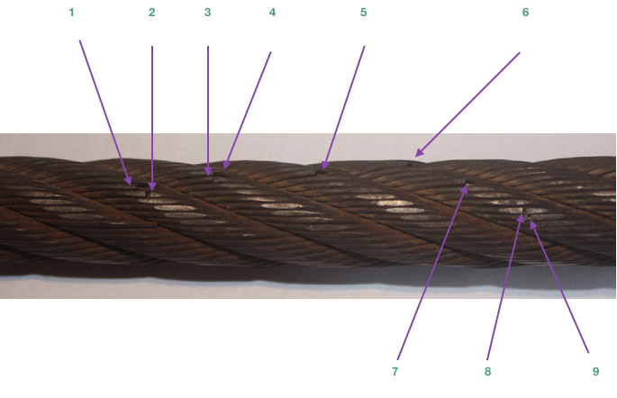
Under normal operating conditions single wires will break due to material fatigue on the crown of a strand. Crown breaks originate at the outside of the rope at the contact point between rope and sheave/drum as shown below.
Valley breaks originate inside the rope and are seen in the valley between two strands. Valley breaks hide internal wire failures at the core or at the contact between strand and core. Valley break may indicate internal rope deterioration, requiring closer inspection of this section of rope. Picture of a rope with valley brake wires is given below.
Crown breaks are signs of normal deterioration, but valley breaks indicate an abnormal condition. Generally extreme notching and countless wire breaks is found in core (complete core failure) when valley breaks are noticed. Such condition will result in catastrophic rope failure and hence it is recommended to remove wire rope from service even if a single valley wire break is detected.
All wire rope removal/retirement criteria are based on fatigue wire breaks located at the crown of a strand. Table as per ASME specification showing maximum number of broken crown wires is as under. The removal criteria are based on the use of steel sheaves.
Broken wires at or near the termination indicates high stresses at that position. It can be due to incorrect fitting of the termination. The cause of this deterioration shall be investigated and the termination remade by shortening the rope if sufficient length remains for further use. If this is not possible, the rope shall be discarded.
In applications where major cause of rope deterioration is fatigue, broken wires will appear after a certain period of use and the number of breaks will progressively increase with usage time. In such cases it is recommended that careful periodic examination and recording of the number of broken wires is carried out with a view to establish the rate of increase in the number of broken wires. The trend can be used to plan wire rope replacement.
The round outer wires of standard wire rope will become flat on the outside due to friction when they come in contact with drums, sheaves, or other abrasive matter like sand or gravel. This is part of normal service deterioration. As shown below, when the surface wires are worn by 1/3 or more of their diameter, the rope must be replaced.
There will be always a normal continuous small decrease in diameter throughout the rope"s service life. Diameter reduction after the break in period is often due to excessive abrasion of the outside wires, internal or external corrosion, inner wire failures and/or inner wire abrasion and deterioration of a fibre core / fracture of a steel core. When core deterioration occurs, it is revealed by a more rapid reduction in diameter. Rope shall be replaced when core deterioration is observed.
Corrosion, while difficult to evaluate, is a more serious cause of degradation than abrasion. It reduces the breaking strength of the rope by reducing the metallic cross-sectional area, and also accelerates fatigue by causing surface irregularities which lead to stress cracking. Usually, it signifies a lack of lubrication. Corrosion often occurs internally before there is any visible external evidence on the rope surface. Corrosion also prevents the rope"s component parts from moving smoothly.
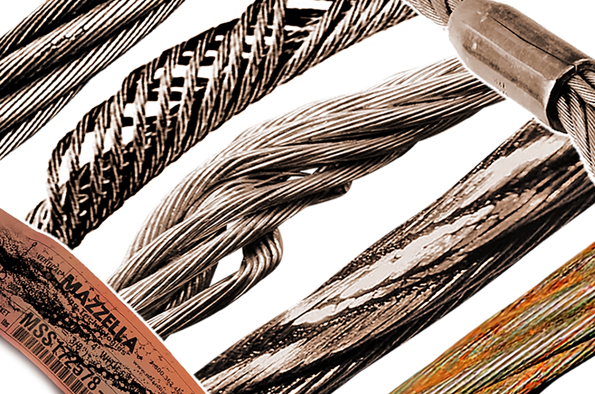
Visible distortion of the rope from its normal shape is termed “deformation” or damage. It is not repairable. It leads to uneven stress distribution in the rope. The magnitude of the deformation may vary from a slight cosmetic damage to total destruction of the wire rope. Kink, crushing, birdcage (also know as basket or lantern formation), core or strand protrusion and wire protrusion are various types of deformations.
Crushing or flattening of the strands can be caused by a number of different factors. These problems usually occur on multilayer spooling applications. Generally crushing conditions occur because of improper installation of the wire rope.
Birdcage is a result of a difference in length between the rope core and the outer layer of strands. Different mechanisms can produce this deformation. For example, when a rope is running over a sheave or onto the drum under a large fleet angle, it will touch the flange of the sheave or the drum groove first and then roll down into the bottom of the groove. This characteristic will unlay the outer layer of strands to a greater extent than the rope core, producing a difference in length between these rope elements. Shock loading also leads to birdcage formation. A birdcage looks as shown below.
Core or strand protrusion is a special type of birdcage in which the rope imbalance is indicated by protrusion of the core between the outer strands, or protrusion of an outer strand of the rope or strand from the core. A photograph of core protrusion is shown below.
As wire rope performance depends upon the condition of the equipment on which it operates, to increase life of a wire rope, corrective actions shall be taken after checking of wire rope at cross points, wedge sockets and other components of a machine like sheave and drums as under.
On multiple layer drums, wire rope will wear out at the crossover points from one wrap to the next. At these crossover points, the rope is subjected to severe abrasion and crushing as it is pushed over the rope "grooves" and rides across the crown of the layer beneath as shown below.
In order to extend the rope"s working life, shortening of the rope at the drum anchoring point of approx. 1/3 of the drum circumference, moves the crossover point to a different section of the rope. Now, a rope section previously not subjected to scrubbing and crushing will take the workload
Examine the grooves for wear. To check the contour and amount of wear, use a gauge. The gauge should contact the groove for about 120 to 150 degrees as shown below.
Replace the sheaves with broken flanges as it enables wire rope to jump the sheave and become badly cut or sheared. If sheaves are wearing on one side, correct the alignment.
Check the sheave / bearings for ease of rotation and wear. Worn bearings cause vibration in the rope, increasing wire fatigue. Repair the bearings or replace the sheave.
Wire ropes on vehicle lifting equipment come under a lot of strain during their life span. Fatigue related damage such as broken strands in the outer wires can be caused by numerous things. Typically these kinds of breaks are caused by the stress put on the parts of the rope continually running in or around pulleys and guides.
When a ramp is loaded and operated with a vehicle, the tension of the rop


 8613371530291