
types of wire rope breaks made in china

As specialist for manufacturing quality steel wire ropes over 20 years, our company can supply strong, durable and reliable ropes that capable to minimize your downtime and maximize cost effectiveness. Decades of experience we owned make us know clearly the work you do and capable to provide professional guidance.
We select the best steel or stainless steel as raw material for wire rope manufacturing. Our products are manufactured under strict quality managements and test before they leave the factory.
Our engineers can provide professional advice about picking up optimal steel wire ropes for their application, installation guidance to ensure maximum return in their wire rope system.
As one of the largest manufacturers in China, we can purchase better materials at a lower price. Then we transmit this saving to our customers by providing the most competitive price.
If you are going to pick up steel wire ropes that suit your project perfectly, you must have an ideal about the construction about them. Our company can supply bright wire rope, galvanized wire rope, stainless steel wire rope, compacted wire rope, rotation resistant wire ropes, mining wire rope, elevator wire rope, crane wire rope and gas & oilfield wire ropes. Here are some details to solve the problem that may puzzle you whether you are browsing the web or picking up steel wire ropes.
Bright steel wire ropes mean no surface treatment is applied to the rope. Therefore, they have the lower price among these three wire ropes. Generally, they are fully lubricated to protect the rope from rust and corrosion.
Galvanized steel wire ropes feature compressed zinc coating for providing excellent corrosion resistance. With higher break strength yet lower price than stainless steel, galvanized steel wire ropes are widely used in general engineering applications such as winches and security ropes.
Stainless steel wire ropes, made of quality 304, 305, 316 steels, are the most corrosive type for marine environments and other places subjected to salt water spray. Meanwhile, bright and shiny appearance can be maintained for years rather than dull as galvanized steel wire ropes.
Steel wire ropes are composed of multiple strands of individual wires that surrounding a wire or fiber center to form a combination with excellent fatigue and abrasion resistance. These wires and strands are wound in different directions to from different lay types as follows:
Beside above lay types, alternative lay ropes which combine regular lay and lang lay together and ideal for boom hoist and winch lines, can also be supplied as your request.
Two main methods about seizing steel wire ropes in conjunction with soft or annealing wire or strands to protect cut ends of the ropes form loosening.

Redundancy is very important for safety-relevant applications. If one of individual elements is broken, other elements will take on its function and remain in operation taking advantages of interaction between wires.
Detectability means the capacity to determine the end of service life and the degree of bending fatigue of running wires. As fatigue increase, more external wire breaks so that it is possible to estimate by visible inspection before the condition becoming dangerous.
Normally, elevator wire ropes feature parallel strand construction for reducing incidence of abrasion compared with ropes with cross laid construction. Meanwhile, they have a high fatigue bending life and less wear to running sheaves.
Fiber core, made of natural or synthetic fibers, is widely used in ropes and makes elevator ropes easier to adjust up to the relevant groove shape. Meanwhile, fiber core provides excellent resistance against contact pressure and long-term support for elevator wire ropes.
Independent wire rope core effectively increases the metallic cross-section of elevator wire ropes and reduce tensile stress in individual wires. Meanwhile, steel cores low the elongation of elevator wire ropes under same loads compared with fiber core.

A competent person must begin a visual inspection prior to each shift the equipment is used, which must be completed before or during that shift. The inspection must consist of observation of wire ropes (running and standing) that are likely to be in use during the shift for apparent deficiencies, including those listed in paragraph (a)(2) of this section. Untwisting (opening) of wire rope or booming down is not required as part of this inspection.
Significant distortion of the wire rope structure such as kinking, crushing, unstranding, birdcaging, signs of core failure or steel core protrusion between the outer strands.
In running wire ropes: Six randomly distributed broken wires in one rope lay or three broken wires in one strand in one rope lay, where a rope lay is the length along the rope in which one strand makes a complete revolution around the rope.
In rotation resistant ropes: Two randomly distributed broken wires in six rope diameters or four randomly distributed broken wires in 30 rope diameters.
In pendants or standing wire ropes: More than two broken wires in one rope lay located in rope beyond end connections and/or more than one broken wire in a rope lay located at an end connection.
If a deficiency in Category I (see paragraph (a)(2)(i) of this section) is identified, an immediate determination must be made by the competent person as to whether the deficiency constitutes a safety hazard. If the deficiency is determined to constitute a safety hazard, operations involving use of the wire rope in question must be prohibited until:
If the deficiency is localized, the problem is corrected by severing the wire rope in two; the undamaged portion may continue to be used. Joining lengths of wire rope by splicing is prohibited. If a rope is shortened under this paragraph, the employer must ensure that the drum will still have two wraps of wire when the load and/or boom is in its lowest position.
If a deficiency in Category II (see paragraph (a)(2)(ii) of this section) is identified, operations involving use of the wire rope in question must be prohibited until:
The employer complies with the wire rope manufacturer"s established criterion for removal from service or a different criterion that the wire rope manufacturer has approved in writing for that specific wire rope (see § 1926.1417),
If the deficiency is localized, the problem is corrected by severing the wire rope in two; the undamaged portion may continue to be used. Joining lengths of wire rope by splicing is prohibited. If a rope is shortened under this paragraph, the employer must ensure that the drum will still have two wraps of wire when the load and/or boom is in its lowest position.
If the deficiency (other than power line contact) is localized, the problem is corrected by severing the wire rope in two; the undamaged portion may continue to be used. Joining lengths of wire rope by splicing is prohibited. Repair of wire rope that contacted an energized power line is also prohibited. If a rope is shortened under this paragraph, the employer must ensure that the drum will still have two wraps of wire when the load and/or boom is in its lowest position.
Where a wire rope is required to be removed from service under this section, either the equipment (as a whole) or the hoist with that wire rope must be tagged-out, in accordance with § 1926.1417(f)(1), until the wire rope is repaired or replaced.
The inspection must include any deficiencies that the qualified person who conducts the annual inspection determines under paragraph (c)(3)(ii) of this section must be monitored.
Wire ropes on equipment must not be used until an inspection under this paragraph demonstrates that no corrective action under paragraph (a)(4) of this section is required.
At least every 12 months, wire ropes in use on equipment must be inspected by a qualified person in accordance with paragraph (a) of this section (shift inspection).
The inspection must be complete and thorough, covering the surface of the entire length of the wire ropes, with particular attention given to all of the following:
Exception: In the event an inspection under paragraph (c)(2) of this section is not feasible due to existing set-up and configuration of the equipment (such as where an assist crane is needed) or due to site conditions (such as a dense urban setting), such inspections must be conducted as soon as it becomes feasible, but no longer than an additional 6 months for running ropes and, for standing ropes, at the time of disassembly.
If the deficiency is localized, the problem is corrected by severing the wire rope in two; the undamaged portion may continue to be used. Joining lengths of wire rope by splicing is prohibited. If a rope is shortened under this paragraph, the employer must ensure that the drum will still have two wraps of wire when the load and/or boom is in its lowest position.
Wire rope and cable are each considered a “machine”. The configuration and method of manufacture combined with the proper selection of material when designed for a specific purpose enables a wire rope or cable to transmit forces, motion and energy in some predetermined manner and to some desired end.
Two or more wires concentrically laid around a center wire is called a strand. It may consist of one or more layers. Typically, the number of wires in a strand is 7, 19 or 37. A group of strands laid around a core would be called a cable or wire rope. In terms of product designation, 7 strands with 19 wires in each strand would be a 7×19 cable: 7 strands with 7 wires in each strand would be a 7×7 cable.
Materials Different applications for wire rope present varying demands for strength, abrasion and corrosion resistance. In order to meet these requirements, wire rope is produced in a number of different materials.
Stainless Steel This is used where corrosion is a prime factor and the cost increase warrants its use. The 18% chromium, 8% nickel alloy known as type 302 is the most common grade accepted due to both corrosion resistance and high strength. Other types frequently used in wire rope are 304, 305, 316 and 321, each having its specific advantage over the other. Type 305 is used where non-magnetic properties are required, however, there is a slight loss of strength.
Galvanized Carbon Steel This is used where strength is a prime factor and corrosion resistance is not great enough to require the use of stainless steel. The lower cost is usually a consideration in the selection of galvanized carbon steel. Wires used in these wire ropes are individually coated with a layer of zinc which offers a good measure of protection from corrosive elements.
Cable Construction The greater the number of wires in a strand or cable of a given diameter, the more flexibility it has. A 1×7 or a 1×19 strand, having 7 and 19 wires respectively, is used principally as a fixed member, as a straight linkage, or where flexing is minimal.
Cables designed with 3×7, 7×7 and 7×19 construction provide for increasing degrees of flexibility but decreased abrasion resistance. These designs would be incorporated where continuous flexing is a requirement.
Selecting Wire Rope When selecting a wire rope to give the best service, there are four requirements which should be given consideration. A proper choice is made by correctly estimating the relative importance of these requirements and selecting a rope which has the qualities best suited to withstand the effects of continued use. The rope should possess:Strength sufficient to take care of the maximum load that may be applied, with a proper safety factor.
Strength Wire rope in service is subjected to several kinds of stresses. The stresses most frequently encountered are direct tension, stress due to acceleration, stress due to sudden or shock loads, stress due to bending, and stress resulting from several forces acting at one time. For the most part, these stresses can be converted into terms of simple tension, and a rope of approximately the correct strength can be chosen. As the strength of a wire rope is determined by its, size, grade and construction, these three factors should be considered.
Safety Factors The safety factor is the ratio of the strength of the rope to the working load. A wire rope with a strength of 10,000 pounds and a total working load of 2,000 pounds would be operating with a safety factor of five.
It is not possible to set safety factors for the various types of wire rope using equipment, as this factor can vary with conditions on individual units of equipment.
The proper safety factor depends not only on the loads applied, but also on the speed of operation, shock load applied, the type of fittings used for securing the rope ends, the acceleration and deceleration, the length of rope, the number, size and location of sheaves and drums, the factors causing abrasion and corrosion and the facilities for inspection.
Fatigue Fatigue failure of the wires in a wire rope is the result of the propagation of small cracks under repeated applications of bending loads. It occurs when ropes operate over comparatively small sheaves or drums. The repeated bending of the individual wires, as the rope bends when passing over the sheaves or drums, and the straightening of the individual wires, as the rope leaves the sheaves or drums, causing fatigue. The effect of fatigue on wires is illustrated by bending a wire repeatedly back and forth until it breaks.
The best means of preventing early fatigue of wire ropes is to use sheaves and drums of adequate size. To increase the resistance to fatigue, a rope of more flexible construction should be used, as increased flexibility is secured through the use of smaller wires.
Abrasive Wear The ability of a wire rope to withstand abrasion is determined by the size, the carbon and manganese content, the heat treatment of the outer wires and the construction of the rope. The larger outer wires of the less flexible constructions are better able to withstand abrasion than the finer outer wires of the more flexible ropes. The higher carbon and manganese content and the heat treatment used in producing wire for the stronger ropes, make the higher grade ropes better able to withstand abrasive wear than the lower grade ropes.
Effects of Bending All wire ropes, except stationary ropes used as guys or supports, are subjected to bending around sheaves or drums. The service obtained from wire ropes is, to a large extent, dependent upon the proper choice and location of the sheaves and drums about which it operates.
A wire rope may be considered a machine in which the individual elements (wires and strands) slide upon each other when the rope is bent. Therefore, as a prerequisite to the satisfactory operation of wire rope over sheaves and drums, the rope must be properly lubricated.
Loss of strength due to bending is caused by the inability of the individual strands and wires to adjust themselves to their changed position when the rope is bent. Tests made by the National Institute of Standards and Technology show that the rope strength decreases in a marked degree as the sheave diameter grows smaller with respect to the diameter of the rope. The loss of strength due to bending wire ropes over the sheaves found in common use will not exceed 6% and will usually be about 4%.
The bending of a wire rope is accompanied by readjustment in the positions of the strands and wires and results in actual bending of the wires. Repetitive flexing of the wires develops bending loads which, even though well within the elastic limit of the wires, set up points of stress concentration.
The fatigue effect of bending appears in the form of small cracks in the wires at these over-stressed foci. These cracks propagate under repeated stress cycles, until the remaining sound metal is inadequate to withstand the bending load. This results in broken wires showing no apparent contraction of cross section.
Experience has established the fact that from the service view-point, a very definite relationship exists between the size of the individual outer wires of a wire rope and the size of the sheave or drum about which it operates. Sheaves and drums smaller than 200 times the diameter of the outer wires will cause permanent set in a heavily loaded rope. Good practice requires the use of sheaves and drums with diameters 800 times the diameter of the outer wires in the rope for heavily loaded fast-moving ropes.
It is impossible to give a definite minimum size of sheave or drum about which a wire rope will operate with satisfactory results, because of the other factors affecting the useful life of the rope. If the loads are light or the speed slow, smaller sheaves and drums can be used without causing early fatigue of the wires than if the loads are heavy or the speed is fast. Reverse bends, where a rope is bent in one direction and then in the opposite direction, cause excessive fatigue and should be avoided whenever possible. When a reverse bend is necessary larger sheaves are required than would be the case if the rope were bent in one direction only.
Stretch of Wire Rope The stretch of a wire rope under load is the result of two components: the structural stretch and the elastic stretch. Structural stretch of wire rope is caused by the lengthening of the rope lay, compression of the core and adjustment of the wires and strands to the load placed upon the wire rope. The elastic stretch is caused by elongation of the wires.
The structural stretch varies with the size of core, the lengths of lays and the construction of the rope. This stretch also varies with the loads imposed and the amount of bending to which the rope is subjected. For estimating this stretch the value of one-half percent, or .005 times the length of the rope under load, gives an approximate figure. If loads are light, one-quarter percent or .0025 times the rope length may be used. With heavy loads, this stretch may approach one percent, or .01 times the rope length.
The elastic stretch of a wire rope is directly proportional to the load and the length of rope under load, and inversely proportional to the metallic area and modulus of elasticity. This applies only to loads that do not exceed the elastic limit of a wire rope. The elastic limit of stainless steel wire rope is approximately 60% of its breaking strength and for galvanized ropes it is approximately 50%.
Preformed Wire Ropes Preformed ropes differ from the standard, or non-preformed ropes, in that the individual wires in the strands and the strands in the rope are preformed, or pre-shaped to their proper shape before they are assembled in the finished rope.
This, in turn, results in preformed wire ropes having the following characteristics:They can be cut without the seizings necessary to retain the rope structure of non-preformed ropes.
They are substantially free from liveliness and twisting tendencies. This makes installation and handling easier, and lessens the likelihood of damage to the rope from kinking or fouling. Preforming permits the more general use of Lang lay and wire core constructions.
Removal of internal stresses increase resistance to fatigue from bending. This results in increased service where ability to withstand bending is the important requirement. It also permits the use of ropes with larger outer wires, when increased wear resistance is desired.
Outer wires will wear thinner before breaking, and broken wire ends will not protrude from the rope to injure worker’s hands, to nick and distort adjacent wires, or to wear sheaves and drums. Because of the fact that broken wire ends do not porcupine, they are not as noticeable as they are in non-preformed ropes. This necessitates the use of greater care when inspecting worn preformed ropes, to determine their true condition.
Manufactured in Calgary this cable is made by coating offshore aircraft cable with a tough and durable PVC coating. The colour is flat black to best fade into the background.
smaller sized cables, we find using an oversized thimble often makes the attachment of fittings easier. Below is a 1/8” standard, a 3/16 AN Zn, and a 1/8” AN Zn Thimble.
Often generically referred to as Crosby clips and occasionally as bulldogs we offer both forged and malleable wire rope clips. Forged clips are required for use in overhead lifting. The malleable clips are recommended for non critical light duty applications such as guard rails, guy wires etc. The efficiency rating on the proper number of properly applied wire rope clips is 80% of the strength of the wire rope. We offer both offshore and Genuine Crosbie Wire Rope Clips. Fist Grips have a couple of advantages over Wire Rope clips in that they are impossible to apply incorrectly and they damage the rope less in situations where the clip will be removed.
Wire rope clips must be re tightened after applying load. In accordance with good rigging practice wire rope and its terminations should be regularly inspected.
Different Brand or trademark names for similar but very different products. When looking at a lifting sling from an aluminum tube’s point of view, it prefers supple, soft and nonabrasive slings. A round sling is the prefect choice rather than a steel sling. Round slings are made of many strands of polyester covered with a protective polyester sheath.
Unfortunately, polyester melts at approx. 250°C (~480°F). Research has shown that a 2k luminair-housing can reach temperatures of about 190°C (~370°F), with the truss-chord straight over it being almost 140°C (~280°F). Accidents have been reported of round slings being melted by spots, pyro or the heat of the rays, and as a result, trusses have fallen. When round slings are used, a safety backup must be applied such as a wire rope or chain sling.
So rather than have a backup steel sling why not make the sling out of steel but softer than a single cable. A steel round sling has a normal outside webbing for soft slings, but instead of the polyamide core, the steel round sling has a core made of many small steel cables, which makes it resistant to high temperatures. The steel wires within the steel round are as flexible as a normal soft sling, but have a much better fire resistance. The steel round can be used in circumstances where the normal soft slings are not allowed.
The outside webbing is black, including an identification label and a hidden inspection window to inspect the steel wires within the sling. The wire-rope core has better heat resistance than the truss itself.
Down Stage Right can supply most of your rope and cordage requirements from twill tape and black cotton tie line to large diameter manila and polyester ropes and braids. To make life very very confusing the synthetic fibre ropes are all available in either a 3 strand, solid braid, double braid or parallel core configuration in nylon, polyester or more exotic materials. Polyester ropes are available in a spun or non spun finish. Due to the huge number of different sizes, colours, materials and braid types combinations (and to simplify things) Down Stage Right Industries stocks several favourites that we have found the theatrical industry usually purchases. If you need a particular rope we are happy to bring in the particular configuration and colour that you want. Please call for details or recommendations for a particular product.
Twill tape is a flat twill-woven ribbon of cotton, linen, polyester, or wool. Used in attaching soft goods and electrical cables to pipes we offer both cotton and polyester twill in 100 yard rolls.
Used as a general purpose tie line for drops or cables it is offered in 1000 and 3000" spools. Available in cotton and polyester. Size 4, #4.5 or 1/8” and #5.
The primary advantage of sash cords are their handling characteristics and their knot holding ability. It does not have the strength or durability of double braids. Available in white as a cotton polyester blend or in black as spun polyester. Sash braid is generally a coarser cousin of solid braid.
Often mislabeled as hemp, manila is significantly stronger and is used in for hand lines in counterweight rigging and as general purpose spot line rope. We only carry #1 grade sea worthy manila. Manila has generally been replaced by synthetics in our industry
Working loads are guidelines only. Once put into service rope is continually deteriorating. Manila rope will deteriorate in storage even under ideal conditions.
Solid braid ropes are sometimes referred to as “sash cord” because this pattern was used to raise sash windows. It is formed by braiding 8 to 18 strands in a reasonably complicated pattern with all the strands rotating in the same direction on the braider. The individual stitches are oriented in the same direction as the rope. The center may contain a filler core. These ropes maintain their round shape well and therefore work exceptionally well in pulleys and sheaves. They tend to have high elongation and are generally less strong than other forms of construction, and are difficult to splice.
"Double braid" ropes, also referred to as "Marine Ropes" or "Yacht Braid" or “2 in 1” are perhaps the most well known braided rope on the market today. They are constructed of a hollow braided rope, which acts as a core inside another braided rope. The combination of the 2 ropes in 1 results in a rope with higher tensile strength than commonly found in twisted ropes. The inner rope and outer rope are generally designed to share the load fairly evenly. Double braid ropes have a torque free construction, and are easily spliced. However, caution must be exercised where double braid ropes are run over pulleys, through hardware or in any situation where the outer rope may slide along on the inner rope and bunch up. This condition, often called "milking", will cause dramatic loss of strength by causing the entire load to go onto the inner rope, because the sheath is bunched up and therefore not under the same tension as the inner rope. Polyester double braid ropes big advantage is that they do not have the same stretch as nylon. They can also be made with a soft “spun” covering giving a better hand feel. The elasticity of nylon ropes can absorb sudden shock loads that would break other ropes.
Manufactured by New England Ropes Stage Set X is a superior replacement for manila with a longer life, much higher strength and no slivers. This rope was specially developed as a replacement for manila hand lines in counterweight rigging and we find it to be Cadillac of the synthetic hand line ropes. Multiline II is a three stranded rope with the same ideals in mind. It is more economically priced and has slightly different handling characteristics.
PRODUCT DESCRIPTION: New England Ropes" Stage-Set X is the softest, strongest and most environmentally stable product available in the theatre industry for counterweight systems. It"s parallel core of polyester fibre contained within a helically wrapped polyester tape and covered by a braided polyester jacket, remains firm and round under all load conditions and resists crushing in rope locks.
Compliance to the above specifications is based upon testing according to the Cordage Institute Standard Testing Methods for Fiber Rope and/or ASTM D-4268 Standard Methods of Testing Fiber Ropes.
Tensile strengths - Are approximate average for new, unused ropes. To estimate the minimum tensile strength of a new rope, reduce the approximate average by 15% (Cordage Institute defines minimum tensile strength as two standard deviations below the average tensile strength of the rope).
Good resistance to the passage of electrical current. However in rope form, dirt, surface contaminants, water entrapment and the like can significantly affect dielectric properties. Extreme caution should be exercise any time a rope is in the proximity of live circuits.
No blanket working load recommendation can be made because it depends on the application and conditions of use, especially potential danger to personnel. It is recommended that the user establish working loads and safety factors based on professional and experienced assessments of risks. The working load is a guideline for the use of a rope in good condition for non-critical applications and should be reduced where life, limb, or valuable property is involved, or exceptional service such as shock, sustained loading, severe vibration, etc.
The Cordage Institute specifies that the Safe Working Load of a rope shall be determined by dividing the Minimum Tensile Strength by the Safety Factor. Safety factors range from 5 to 12 for non-critical uses, 15 for life lines.
PRODUCT DESCRIPTION: Multiline II is a 3-strand composite rope, its unique construction combines filament and staple/spun polyester wrapped around a polyolefin core (smaller than 1/2" diameter does not have polyolefin core). Multiline II feels and handles like manila, yet provides greater durability, higher strength, lighter weight, and a consistent supple feel over time.
Compliance to the above specifications is based upon testing according to the Cordage Institute Standard Testing Methods for Fiber Rope and/or ASTM D-4268 Standard Methods of Testing Fiber Ropes.
Tensile strengths - Are approximate average for new, unused ropes. To estimate the minimum tensile strength of a new rope, reduce the approximate average by 15% (Cordage Institute defines minimum tensile strength as two standard deviations below the average tensile strength of the rope).
Good resistance to the passage of electrical current. However in rope form, dirt, surface contaminants, water entrapment and the like can significantly affect dielectric properties. Extreme caution should be exercise any time a rope is in the proximity of live circuits.
No blanket working load recommendation can be made because it depends on the application and conditions of use, especially potential danger to personnel. It is recommended that the user establish working loads and safety factors based on professional and experienced assessments of risks. The working load is a guideline for the use of a rope in good condition for non-critical applications and should be reduced where life, limb, or valuable property is involved, or exceptional service such as shock, sustained loading, severe vibration, etc.
The Cordage Institute specifies that the Safe Working Load of a rope shall be determined by dividing the Minimum Tensile Strength by the Safety Factor. Safety factors range from 5 to 12 for non-critical uses, 15 for life lines.
Wire ropes are structural components made of twisted wire that are widely employed in diverse areas. The safe usage of wire ropes is directly related to the production lifetime and personnel safety. Therefore, it is of great significance to develop an online detection and quantitative inspection system for wire ropes [1]. ElectroMagnetic Testing (EMT), the advantages of which include low cost, high reliability, and suitability for online detection of wire rope, has been widely used in wire rope application. EMTs include eddy current testing, magnetic particle testing, Magnetic Flux Leakage (MFL) detection, magnetic memory detection, microwave detection, and other methods. Among these, the MFL method can detect the surface and internal defects of wire rope, and has been greatly developed for its simple structure and portability [2].
In a traditional MFL detection, wire rope is magnetized to saturation, after which a magnetic probe is used to measure the MFL distribution. According to the form of the magnetic field source, there are two techniques: coil magnetization [3,4] and permanent magnet magnetization [5,6,7,8,9,10]. Singh [3] designed a magnetized device consisting of a variable-current saddle-shaped coil. This apparatus can be adjusted by controlling the magnitude of the current, but the device cannot be continuously used for the massive heating of the coil. Jomdecha et al. [4] improved a coil device of solenoid structure instead of traditional coil magnetizer. The magnetic field strength can be adjusted by changing the magnetizing current or magnetizing coil number. The multiple symmetrical yoke structures were composed of circumferentially distributed wire rope to magnetize its uniform saturation [5,6,7,8]. Wang et al. [9] considered the effects of different lift-off distances on detection accuracy during the magnetization process, and proposed an improved magnetization device. Xu et al. [11] used the finite element analysis method to optimize the structure of the excitation device, which was then validated by the experiment.
In a testing system, the magnetic field is converted into an electrical signal by a magnetic-to-electric convertor, such as an induction coil, a fluxgate, a Hall element, or a magnetoresistive sensor. Cao [12] proposed a detection device based on a Printed Circuit Board (PCB) split differential coil, obtaining a sum of MFL circumferential distribution signals. The device is useful for a certain span in the axial direction of the wire rope, but it is not sensitive to small width defects and circumferential defect information. Jomdecha et al. [4] improved the traditional induction coil by designing an induction coil array, with coils arranged on the circumferential wire rope. This system solved the problem of MFL circumferential information loss. Zhao et al. [13] designed a detection device in which 30 Hall sensors evenly surround the circumferential wire rope. This device can effectively obtain the information of the circumferential MFL distribution, but the Signal-to-Noise Ratio (SNR) of the collected signal is low. Peterka et al. [14] presented the results obtained by tracking the magnetic flux around the cable end and the signal runs from a particular design. Additionally, they investigated scanning elements placed above artificial defects created close to the cable end.
The signal that is collected by magnetic sensors contains ample background noise, so it is necessary to filter system noise. Cao et al. [12] proposed an algorithm for adaptive parameter spatial notch filtering to suppress strand wave, and the wavelet packet was used to filter out the high-frequency random noise. Zhang et al. [15,16] used the wavelet based on compressed sensing to denoise the strand wave and high-frequency noise, and then further proposed a channel-balance method based on the Hilbert-Huang transformation. Zhang et al. [17] used a spatial filter to reduce noise and smoothen the defect image. Zhang et al. [18] pretreated the MFL grayscale and effectively suppressed the noise interference. Tian et al. [19] combined the wavelet transform and the morphological transform to create a morphological filter algorithm that suppressed the interference associated with the baseline drift in the wire rope signal.
There are some problems among the existing MFL methods for defect detection in wire ropes:the excitation devices are cumbersome and inconvenient, the defect cannot be positioned in the circumferential direction, the wire rope is magnetized unevenly, and the SNR is low. A device to detect wire rope surface remanence strength was designed to solve these problems, and this solution is described in this paper. The wire rope was magnetized by permanent magnets, and the MFL information of the wire rope surface was collected after magnetization with giant magnetoresistive sensors, arranged evenly around the circumference of the wire rope. A wavelet filtering method based on Ensemble Empirical Mode Decomposition (EEMD) was used to denoise the original signal. The two-dimensional defect signal was processed and analyzed by digital image technology. To achieve quantitative classification, the defect image characteristics were extracted to express the MFL distribution information. The processing data were normalized to obtain the MFL grayscale image. The cubic spline interpolation was used to improve the circumferential resolution. The method of modulus maxima was used to locate and segment defects from the MFL image. The wavelet super-resolution reconstruction method was used to improve the resolution of the segmented image. Image descriptions of area, rectangle, elongation, and seven invariant moments were extracted as the feature vector of the defect, which was the input of a Back Propagation (BP) neural network, used to classify the defects.
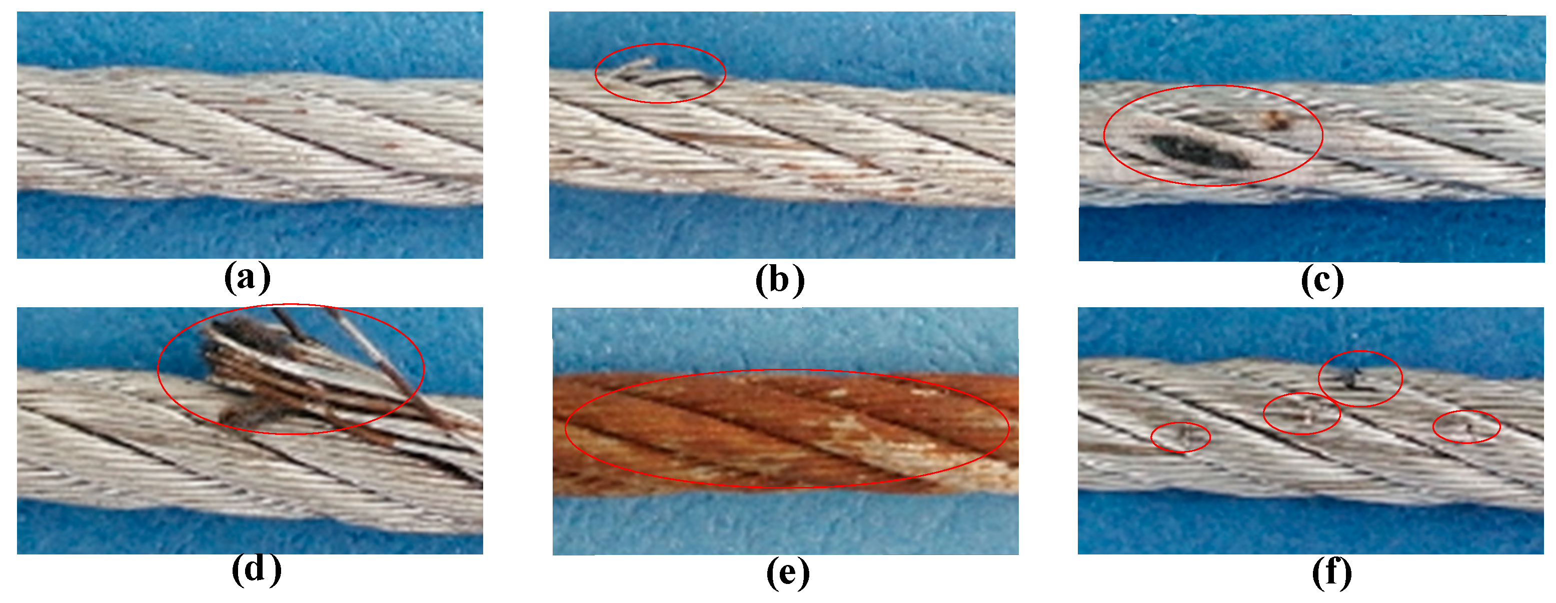
Steel wire ropes have important applications in mine lifting, cable-stayed bridges, metallurgy, elevators, and so on. They are widely used due to their high strength, light weight, reliability, and efficiency [1]. Since wire ropes usually work in harsh environments, although they suffer from a variety of types of damage such as broken wire and wear, which affects the safety of production and even threatens the lives of workers [2]. To avoid accidents, manual inspection and regular replacement are generally used in engineering. However, manual inspection is time-consuming and laborious, and regular replacement usually causes great economic waste. According to a survey, more than 70% of replaced wire ropes still have initial breaking strength [3]. Therefore, it is of great importance to develop scientific and effective devices to inspect steel wire ropes.
There are two types of defects of steel wire ropes, loss of metallic cross-sectional area (LMA) and a localized fault (LF), and broken wire is the most typical outcome of LF. Among the various nondestructive testing techniques, magnetic flux leakage (MFL) method is most economical and effective for broken wire detection [4,5,6,7,8]. The basic principle of the MFL method is shown in Figure 1, where the permanent magnet magnetizes part of the wire rope to saturation, and a closed magnetic circuit is formed between the wire rope, the magnet and the yoke. When no damage is present, most of the magnetic induction lines pass through the inside of the wire rope. When there is a damage such as broken wire, the magnetic resistance of the damaged position increases, and part of the magnetic induction line leaks out to form the MFL. Magnetic sensitive elements are placed between the poles of the magnet to sense the MFL signal. The condition of the wire rope can be determined according to the received signal.
For decades, many experts and scholars have done a lot of research on the design of damage detecting sensors based on the MFL method [9,10,11,12,13]. Cao Y.N. et al. [9] proposed an approach for detecting LF of steel wire ropes using an annular array of Hall components. A back propagation (BP) network is used to classify the faults. This method can differentiate the degree and the width of local defects. Zhang J. et al. [10] applied the giant magneto-resistance (GMR) sensor to the detection of LF and LMA of the wire rope. Through the use of compressed sensing wavelet filtering and BP neural network, the accuracy and reliability of MFL sensor is improved. Wu B. [13] designed an MFL sensor based on tunnel magneto-resistive device. A blind hole with dimension of 0.3 mm in both depth and diameter is detectable for the sensor. The axial resolution to two adjacent notches with a width of 0.2 mm of the TMR-based MFL sensor can be less than 2.5 mm. However, arranging annular arrays of Hall components undoubtedly increases the complexity of the signal processing. Using magneto-resistive sensors can improve the sensitivity of the sensor, but it is difficult to be applied to actual inspections due to the micron-level requirements of the lift-off [13]. Therefore, designing a sensor that can be applied to the detection in actual engineering and is both simple and effective, has always been a problem for the condition monitoring of wire ropes.
The magnetic concentrating detection technology provides a new direction for the development of MFL sensors. The detection of wire ropes usually requires the arrangement of a plurality of magnetic sensitive elements. Especially for the large diameter wire ropes, it usually needs dozens of magnetic sensors, which greatly increases the difficulty of signal processing in the later stage. The magnetic concentrating principle can realize the leak-free detection of large diameter wire ropes through a small number of magnetic sensitive elements [14,15]. Kang et al. [14] theoretically analyzed the feasibility of magnetic concentrating detection. It is proved by calculation that the magnetic concentrator can collect the MFL and guide it into the Hall component through the bridge between the concentrators to realize the collection of weak leakage flux. At the same time, it can eliminate the strand-waveform noise of wire ropes and improve signal-to-noise ratio of the MFL signal. Wang et al. [15] analyzed the performance of the magnetic concentrators on collecting the MFL by finite element simulation and proposed the structure which is suitable for collecting the magnetic leakage flux. The structure was verified by experiments, which further promoted the development of the magnetic concentrating detection.
In this study, a sensor, which is constructed of ring-shaped magnets, a yoke, and a magnetic concentrator, is designed to detect broken wires of steel wire ropes. We optimized the structural parameters of the circumferential multi-circuit permanent magnet exciter (CMPME) and analyzed the performance of the magnetic concentrator on collecting MFL through the finite element method. Finally, the proposed sensor is applied in an experiment for broken wire detection. The induced MFL signal can be clearly recognized and the signal-to-noise ratio of the MFL signal is improved by discrete wavelet transform (DWT).
The rest of the paper is organized as follows. Section 2 describes the design principle of the magnetic circuit of the CMPME and the basic theory of magnetic concentrating detection. In Section 3, the structure parameters of the exciter are optimized by simulation, and the performance of the magnetic concentrator on collecting MFL is analyzed. Section 4 illustrates the experimental settings, steps and result analysis. Finally, the conclusions are drawn in Section 5.
Below in conjunction with accompanying drawing, the preferred embodiments of the present invention are described in detail, can be easier to make advantages and features of the invention be readily appreciated by one skilled in the art, thus more explicit defining is made to protection scope of the present invention.
Design of the present invention is: according to splice length, with flat awl, first section steel wire rope rope strand is enrolled in the space of second section steel wire rope rope strand, and then the rope strand of second section steel wire rope is also programmed in the rope strand of first section steel wire rope.Under the effect being subject to external force, tractive force, vertical gravity, each other frictional force, power institute work.Volume is inserted into steel wire in each steel cable rope strand is pushed down, pinning of automatically tying tight, and reaches the object improving steel cable intensity.
Consult shown in Fig. 1-4, the new-type splicing method of steel wire rope of the present invention, comprise for splicing the first steel wire rope 1 of disconnection and the second steel wire rope 2, first steel wire rope 1 and the second steel wire rope 2 steel wire strand and a rope stamen that are mutually wound around respectively, it comprises the following steps:
The first step, respectively first, second steel wire rope (1,2) is respectively broken some stocks, make the first steel wire rope 1 break head and punish into the A rope strand of band rope stamen and the B rope strand not with rope stamen, second steel wire rope 2 breaks head and punishes into the C rope strand of band rope stamen and the D rope strand not with rope stamen, wherein, first steel wire rope 1 and the second steel wire rope 2 are made up of six strands of steel wires and a rope stamen respectively, first, second steel wire rope (1,2) respectively breaks three strands, and the length of its broken head is more than or equal to 1m.
Second step, A rope strand and D rope strand intersected and hand over volume mutually, and leave the remaining rope of A ' respectively and D ' is remaining restricts,
3rd step, the fag end of B rope strand and C rope strand to be cut off, retain respectively its length and A ' remaining restrict with D ' more than length of restricting identical,
4th step, rope more than B rope strand and D ' being interted in the first steel wire rope 1, interting restrict more than C rope strand and A ' in the second steel wire rope 2, and enter two or one method entering three according to one and intert, stick with 18 cones and lock third hand tap greatly.
2. the raising of bonding strength is embodied in for 6 × 37+1 φ is the steel cable of 13mm, the allowable rope load of φ 13mm is 1.69 tons, disrumpent feelings is 8.7 tons, and through hanging thing load test, the knot position intensity of the steel wire rope spliced is greater than 100% of the steel cable rupture pull force of φ 13mm.
3. the connection of steel wire rope, be generally use when not having spare unit or steel cable disconnects suddenly, it is economical and practical, cost-saving, can improve the ability that escorts for the stable yields direct motion of important production station.
Above, be only the specific embodiment of the present invention, but protection scope of the present invention is not limited thereto, any change of expecting without creative work or replacement, all should be encompassed within protection scope of the present invention.Therefore, the protection domain that protection scope of the present invention should limit with claims is as the criterion.

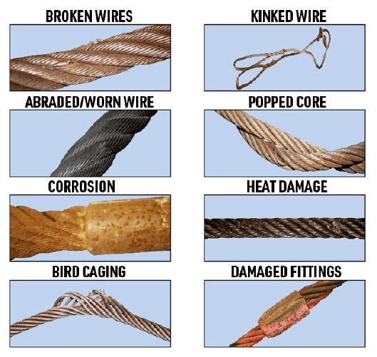
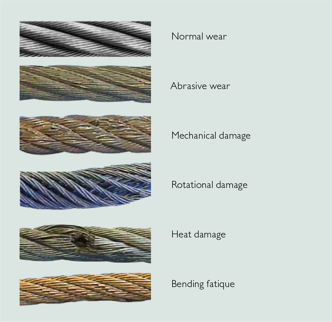
Wire ropes are largely used in marine environment or for rigging purposes. They receive considerable loads and thus suffer a great deal of mechanical damage throughout their service life. Moreover, research has shown that the major cause of wire rope failure is excessive deterioration and corrosion, lack of maintenance and inspection, and wrong usage resulting in early discarding, reduced safety and replacement cost increase.
Sometimes damage can be easily detected, while in other cases fractured wires may occur on the inside. Hence, wire ropes should be inspected and maintained by the right person (competent person assigned by the company), to assure they’re in perfect condition. Regular inspectionsensure high rope performance, long service lifetime , safety of personnel and equipment, and reduced operating costs.
All ropes (synthetic, high modulus and wire ropes) should be inspected before and after an operation. This guideline ensures maximum safety for both a ship’s personnel and equipment. Even though it’s difficult to determine the exact service life span of ropes, there is a way to have a more precise estimation about their efficient lifecycle. Calculating the exact time ropes have been in use (e.g mooring time, mooring conditions, weather and tidal conditions) is the answer. All in all, rope inspections should occur at least once a year.
Inspecting wire ropes in particular, comes with great responsibility. Inspection results should be recorded, and any defects noticed have to be reported and addressed properly. Some defects can be repaired, while in some cases replacing a wire rope is inevitable.
Periodical inspections ofvessel deck equipment is also crucial for maintaining the good condition of wire ropes. The condition of the drum, chocks, bitts, rollers, sheaves, cable clamps and other end fittings, affect the rope’s performance, threads and cords. Make sure to mark these parts during your overall inspection.
In order to help marine officers and staff conduct successful wire rope inspections – and keep an up-to-date record of them – we have created an inspection solution that helps in maintaining and monitoring a ship’s ropes and deck equipment.
When calculating mass using F = Minimum Breaking Force, according to the wire rope’s diameter, you can determine the Minimum Breaking Massand therefore the wire’s max strength. When calculating mass using F = Safe Load according to the wire rope’s diameter, you can determine the Safe Load Mass,which is the advised load for this rope diameter.
The strands of a wire rope absorb the majority of the tensile force applied on the rope. Their design and manufacturing standards affect the level of fatigue resistance and resistance to abrasion. An easy way to understand which rope design is suitable for each purpose, is the wire rope classification.
Wire ropes are classified according to the number of strands in each construction and the number of wires in each strand. For example, a classification of 6X19 means that a wire rope of this type always has six strands, but its wires could be 15-26 per strand. This is because 19 is not the exact number of wires, but the classification of a wire number range.
Visual inspections are a common and fast way to assess wire rope condition. Both the standard and rotation resistant wire rope inspectionprocesscomply with the same four steps of examination. A ship’s crew can perform them as follows:
Steel wire rope distortion is obvious in most cases and can easily be identified by the inspector or the ship‘s crew. It usually occurs if load is suddenly applied or abruptly released (shock loading), or even if swift torque is forcefully induced.
Although not all of these deformations make the rope absolutely dangerous to use, they all may cause ropes to wear unevenly in time. This means inspections should take place more often, and distorted ropes should be handled with caution.
The rag and visual inspection is a good method for regular inspection intervals. The inspector pulls a rag along the rope trying to find broken wire cords. If the rug gets snagged by the rope, the inspector has to stop and assess the wire rope’s condition. Extreme caution should be exercised during the visual inspection, and under no circumstances should this method be the only one used to inspect wire ropes.
Tip: When you encounter a protruding wire end, bend it back and forth manually, until it separates from the wire. This will protect neighboring wires from wearing out.
Diameter reduction is a critical factor in steel wire rope wear and if not properly taken care of, it can result in rope breakage. Excessive abrasion, loss of core mass, corrosion or inner wire failure are all factors that contribute to diameter reduction.
To get an accurate measurement of the rope’s diameter, measure the rope at three different points at least 5 feet apart. Take the average of these three measurements to determine the true diameter.
Any measurements showing a reduction of ⅓ or more, indicate that a replacement should follow without delay. A diameter reduction of less than 1/3 still requires attention, and the inspector or the ship’s crew should be on guard in the next scheduled wire rope inspection.
Failure from abrasion or corrosion is a result of deficient deck equipment inspection or insufficient wire rope lubrication respectively. Internal corrosive damage is more difficult to identify than any other types of degradation. In most cases, the damage has progressed more than the external signs suggest.
Wire rope storage plays a significant role in the rope’s operation life.Wire rope corrosion and pitting can be avoided if ropes are safely stored in a clean, cool, dry and well-ventilated place. Steel wire ropes should not by any means rest on the floor, and should be protected from water, dust or any chemical fumes. Long term storage requires periodic greasing, turning the reel upside down for preventing grease dripping and possibly re-winding to another reel with larger inner tube diameter.
Wire ropes should be maintained with periodical lubrication. In order to prevent internal corrosion, a pressure lubricator is suggested to be used. In this case, a small amount of grease is used to lubricate the rope internally, while the deck stays grease-clean. Pressure lubricators clean the rope before they grease it so that the new grease enters a clean rope. The type of grease used is very important for maximum protection and greasing efficiency.
Steel wire ropes exposed to dirt, grime and other contaminants, have to be cleaned with a wire brush and petroleum (unless a pressure lubricator is used). Optimal cleaning of wire ropes can extend their service life and guarantee safe operations.
The reeling process is of high importance for the longevity of wire ropes. To protect them from being damaged, it is important that the surface of the drum is clean, smooth and dry. Improper reeling may cause wire-rope strands to spread or get flattened, when in contact with one another, as successive layers are being spooled and upper layers apply pressure on the lower ones.
Katradis S.A. offers a wide range of top quality wire ropes for shipping (mooring and hoisting operations), fishing and construction purposes. Our wire ropes have greater resistance to fatigue, and they distribute tension force equally among the rope strands. They are less likely to kink, providing higher staff safety and assuring operation success.


 8613371530291