
u bolt for wire rope free sample

Meets or exceeds all requirements of ASME B30.26 including identification, ductility, design factor, proof load, and temperature requirements. Importantly, these wire rope clips meet other critical performance requirements including fatigue life, impact properties, and material traceability, not addressed by ASME B30.26.

Our team through qualified training. Skilled professional knowledge, powerful sense of support, to satisfy the support desires of consumers for Electrical Lugs Terminals , Adss Dead End Clamp , Square Conductor Clamp , Wanting on the long run, a protracted way to go, continually striving to become the all team with full enthusiasm, one hundred times the confidence and put our company created a beautiful environment, advanced merchandise, good quality first-class modern business and get the job done hard!
Powerlink copper cable lug is used to connect the copper conductor end. It has a Inspection hole to check the conductor location. Material from high conductivity annealed 99.9% copper which gives the best electrical properties possible. Tin plating process, beautiful appearance.
We attempt for excellence, support the customers", hopes to become the top cooperation team and dominator enterprise for staff, suppliers and shoppers, realizes worth share and continual marketing for Factory Free sample U Bolt Rod To Cable Clamp - Bell Mouth Copper Crimp Lug(Australia Standard) – Baolin, The product will supply to all over the world, such as: Greece, Estonia, Manila, We"ve been always creating new technology to streamline the production, and give products with competitive prices and high quality! Customer satisfaction is our priority! You can let us know your idea to develop unique design for your own model to prevent too much similar parts in the market! We are going to present our best service to satisfy all your needs! Remember to contact us right away!

After you pay the sample charge and approval the layout, mostly, the samples will be ready for delivery in3-5 days. The samples will be sent to youvia express, it is ok to use yourown
Yes. We are a professional manufacturer of wire assemblies with 15 years producing experience in China .We have always been cooperating with domestic and overseas customers and partners with the first- class quality and service to make great achievements. If this is your first time to contact us, please trust us, we’ll not let you down.

While these clips are not designed to be used in an overhead lifting situation (swage sleeves should be used instead), wire rope clips are heavy-duty wire rope clips that used for sustaining overhead loads. Examples include guy lines, support lines, scaffolding, etc.
U.S. Cargo Control offers two types of clips: standard (or U-Bolt) and fist-grip (or "double saddle"). Our line includes high-quality clips that work for any situation, including:
Install the first clip at the dead end side of the rope. The "U" side of the clip must always cover the dead end of the rope, and the "saddle" side of the clip on the live end of the rope. Place the nuts of the clip and tighten them using a torque wrench.
Next, apply the second clip and place it as close to the eye loop as possible. Same application for the clip. Tighten the nuts of the clip with a wrench. (If you"re planning on using more than two clips, do not tighten the nuts on the clip.)
Place more clips on the rope if you need more than two on the wire rope. Be sure to space them evenly between the end clips. Finally, tighten the end clips and apply tension to reach the recommended torque for the wire rope.
Sometimes called a u-bolt,u-bolt clip or cable clip, they can be used to join two wire rope ends together, make an eye for a pulling application, or to secure the loose end of a wire rope after a wedge socket (or other appropriate device) has been used to terminate a crane’s hook.
ASME B30.9 states that wire rope clips shall not be used to fabricate wire rope slings, except where the application of slings prevents the use of prefabricated slings.
ASME B30.9 states wire rope clips shall be drop-forged steel of single saddle (u-bolt) or double saddle clip. Malleable cast iron clips shall not be used.
Wire rope clips diminish the working load limit of the wire rope to generally about 70-75% of its original strength. There are better and more efficient ways to fabricate slings for overhead lifting.
For situations where use of wire rope clips are approved, it’s important to remember the proper way to install the clips. Incorrect installation can reduce the working load limit by 40% or more. The easiest thing is to remember, “never saddle a dead horse.”
To comply with manufacturer’s specification the correct number of clips must be installed correctly andtightened to the correct torque using a torque wrench. The correct installation technique is shown below.
The bridge of the wire rope clip should always be placed on the load bearing part of the rope. The U-bolt ofthe clip should be placed on the rope tail, also known as the “dead end” of the rope.
The first clip must be placed one bridge width from the turned back rope tail or dead end of the rope,according to figure 1. Tighten nuts to the specified torque.
The second clip must be placed immediately against the thimble but nevertheless in such a position that thecorrect tightening of the clip does not damage the outer wires of the wire rope (figure 2). Tighten the nutsfirmly but not yet to the specified torque.
During assembly and before the rope is taken into service, the nutsmust be tightenedonce again to theprescribed torque. After the load is applied for the first time, the torque value must be checked again andcorrected if necessary. Periodically re-tightening of the nuts must be done at 10.000 cycles (heavy usage),20.000 e.g. every 3 months, 6 months, annually.
In addition, for clips to work properly and gain their design efficiency, the proper number of clips is required and the nuts must be torqued as prescribed by the manufacturer. For more information on proper installation, check out this video from the Crosby Group.
If you have more questions on wire rope clips, comment below. Remember that Safety through Education is more than just our motto, it is our guiding principle. If you need training on proper application on any other rigging hardware, reach out to us. We are here for you.
In stricter senses, the term wire rope refers to a diameter larger than 9.5 mm (3⁄8 in), with smaller gauges designated cable or cords.wrought iron wires were used, but today steel is the main material used for wire ropes.
Historically, wire rope evolved from wrought iron chains, which had a record of mechanical failure. While flaws in chain links or solid steel bars can lead to catastrophic failure, flaws in the wires making up a steel cable are less critical as the other wires easily take up the load. While friction between the individual wires and strands causes wear over the life of the rope, it also helps to compensate for minor failures in the short run.
Wire ropes were developed starting with mining hoist applications in the 1830s. Wire ropes are used dynamically for lifting and hoisting in cranes and elevators, and for transmission of mechanical power. Wire rope is also used to transmit force in mechanisms, such as a Bowden cable or the control surfaces of an airplane connected to levers and pedals in the cockpit. Only aircraft cables have WSC (wire strand core). Also, aircraft cables are available in smaller diameters than wire rope. For example, aircraft cables are available in 1.2 mm (3⁄64 in) diameter while most wire ropes begin at a 6.4 mm (1⁄4 in) diameter.suspension bridges or as guy wires to support towers. An aerial tramway relies on wire rope to support and move cargo overhead.
Modern wire rope was invented by the German mining engineer Wilhelm Albert in the years between 1831 and 1834 for use in mining in the Harz Mountains in Clausthal, Lower Saxony, Germany.chains, such as had been used before.
Wilhelm Albert"s first ropes consisted of three strands consisting of four wires each. In 1840, Scotsman Robert Stirling Newall improved the process further.John A. Roebling, starting in 1841suspension bridge building. Roebling introduced a number of innovations in the design, materials and manufacture of wire rope. Ever with an ear to technology developments in mining and railroading, Josiah White and Erskine Hazard, principal ownersLehigh Coal & Navigation Company (LC&N Co.) — as they had with the first blast furnaces in the Lehigh Valley — built a Wire Rope factory in Mauch Chunk,Pennsylvania in 1848, which provided lift cables for the Ashley Planes project, then the back track planes of the Summit Hill & Mauch Chunk Railroad, improving its attractiveness as a premier tourism destination, and vastly improving the throughput of the coal capacity since return of cars dropped from nearly four hours to less than 20 minutes. The decades were witness to a burgeoning increase in deep shaft mining in both Europe and North America as surface mineral deposits were exhausted and miners had to chase layers along inclined layers. The era was early in railroad development and steam engines lacked sufficient tractive effort to climb steep slopes, so incline plane railways were common. This pushed development of cable hoists rapidly in the United States as surface deposits in the Anthracite Coal Region north and south dove deeper every year, and even the rich deposits in the Panther Creek Valley required LC&N Co. to drive their first shafts into lower slopes beginning Lansford and its Schuylkill County twin-town Coaldale.
The German engineering firm of Adolf Bleichert & Co. was founded in 1874 and began to build bicable aerial tramways for mining in the Ruhr Valley. With important patents, and dozens of working systems in Europe, Bleichert dominated the global industry, later licensing its designs and manufacturing techniques to Trenton Iron Works, New Jersey, USA which built systems across America. Adolf Bleichert & Co. went on to build hundreds of aerial tramways around the world: from Alaska to Argentina, Australia and Spitsbergen. The Bleichert company also built hundreds of aerial tramways for both the Imperial German Army and the Wehrmacht.
In the last half of the 19th century, wire rope systems were used as a means of transmitting mechanical powercable cars. Wire rope systems cost one-tenth as much and had lower friction losses than line shafts. Because of these advantages, wire rope systems were used to transmit power for a distance of a few miles or kilometers.
Steel wires for wire ropes are normally made of non-alloy carbon steel with a carbon content of 0.4 to 0.95%. The very high strength of the rope wires enables wire ropes to support large tensile forces and to run over sheaves with relatively small diameters.
In the mostly used parallel lay strands, the lay length of all the wire layers is equal and the wires of any two superimposed layers are parallel, resulting in linear contact. The wire of the outer layer is supported by two wires of the inner layer. These wires are neighbors along the whole length of the strand. Parallel lay strands are made in one operation. The endurance of wire ropes with this kind of strand is always much greater than of those (seldom used) with cross lay strands. Parallel lay strands with two wire layers have the construction Filler, Seale or Warrington.
In principle, spiral ropes are round strands as they have an assembly of layers of wires laid helically over a centre with at least one layer of wires being laid in the opposite direction to that of the outer layer. Spiral ropes can be dimensioned in such a way that they are non-rotating which means that under tension the rope torque is nearly zero. The open spiral rope consists only of round wires. The half-locked coil rope and the full-locked coil rope always have a centre made of round wires. The locked coil ropes have one or more outer layers of profile wires. They have the advantage that their construction prevents the penetration of dirt and water to a greater extent and it also protects them from loss of lubricant. In addition, they have one further very important advantage as the ends of a broken outer wire cannot leave the rope if it has the proper dimensions.
Stranded ropes are an assembly of several strands laid helically in one or more layers around a core. This core can be one of three types. The first is a fiber core, made up of synthetic material or natural fibers like sisal. Synthetic fibers are stronger and more uniform but cannot absorb much lubricant. Natural fibers can absorb up to 15% of their weight in lubricant and so protect the inner wires much better from corrosion than synthetic fibers do. Fiber cores are the most flexible and elastic, but have the downside of getting crushed easily. The second type, wire strand core, is made up of one additional strand of wire, and is typically used for suspension. The third type is independent wire rope core (IWRC), which is the most durable in all types of environments.ordinary lay rope if the lay direction of the wires in the outer strands is in the opposite direction to the lay of the outer strands themselves. If both the wires in the outer strands and the outer strands themselves have the same lay direction, the rope is called a lang lay rope (from Dutch langslag contrary to kruisslag,Regular lay means the individual wires were wrapped around the centers in one direction and the strands were wrapped around the core in the opposite direction.
Multi-strand ropes are all more or less resistant to rotation and have at least two layers of strands laid helically around a centre. The direction of the outer strands is opposite to that of the underlying strand layers. Ropes with three strand layers can be nearly non-rotating. Ropes with two strand layers are mostly only low-rotating.
Stationary ropes, stay ropes (spiral ropes, mostly full-locked) have to carry tensile forces and are therefore mainly loaded by static and fluctuating tensile stresses. Ropes used for suspension are often called cables.
Track ropes (full locked ropes) have to act as rails for the rollers of cabins or other loads in aerial ropeways and cable cranes. In contrast to running ropes, track ropes do not take on the curvature of the rollers. Under the roller force, a so-called free bending radius of the rope occurs. This radius increases (and the bending stresses decrease) with the tensile force and decreases with the roller force.
Wire rope slings (stranded ropes) are used to harness various kinds of goods. These slings are stressed by the tensile forces but first of all by bending stresses when bent over the more or less sharp edges of the goods.
Technical regulations apply to the design of rope drives for cranes, elevators, rope ways and mining installations. Factors that are considered in design include:
Donandt force (yielding tensile force for a given bending diameter ratio D/d) - strict limit. The nominal rope tensile force S must be smaller than the Donandt force SD1.
The wire ropes are stressed by fluctuating forces, by wear, by corrosion and in seldom cases by extreme forces. The rope life is finite and the safety is only ensured by inspection for the detection of wire breaks on a reference rope length, of cross-section loss, as well as other failures so that the wire rope can be replaced before a dangerous situation occurs. Installations should be designed to facilitate the inspection of the wire ropes.
Lifting installations for passenger transportation require that a combination of several methods should be used to prevent a car from plunging downwards. Elevators must have redundant bearing ropes and a safety gear. Ropeways and mine hoistings must be permanently supervised by a responsible manager and the rope must be inspected by a magnetic method capable of detecting inner wire breaks.
The end of a wire rope tends to fray readily, and cannot be easily connected to plant and equipment. There are different ways of securing the ends of wire ropes to prevent fraying. The common and useful type of end fitting for a wire rope is to turn the end back to form a loop. The loose end is then fixed back on the wire rope. Termination efficiencies vary from about 70% for a Flemish eye alone; to nearly 90% for a Flemish eye and splice; to 100% for potted ends and swagings.
When the wire rope is terminated with a loop, there is a risk that it will bend too tightly, especially when the loop is connected to a device that concentrates the load on a relatively small area. A thimble can be installed inside the loop to preserve the natural shape of the loop, and protect the cable from pinching and abrading on the inside of the loop. The use of thimbles in loops is industry best practice. The thimble prevents the load from coming into direct contact with the wires.
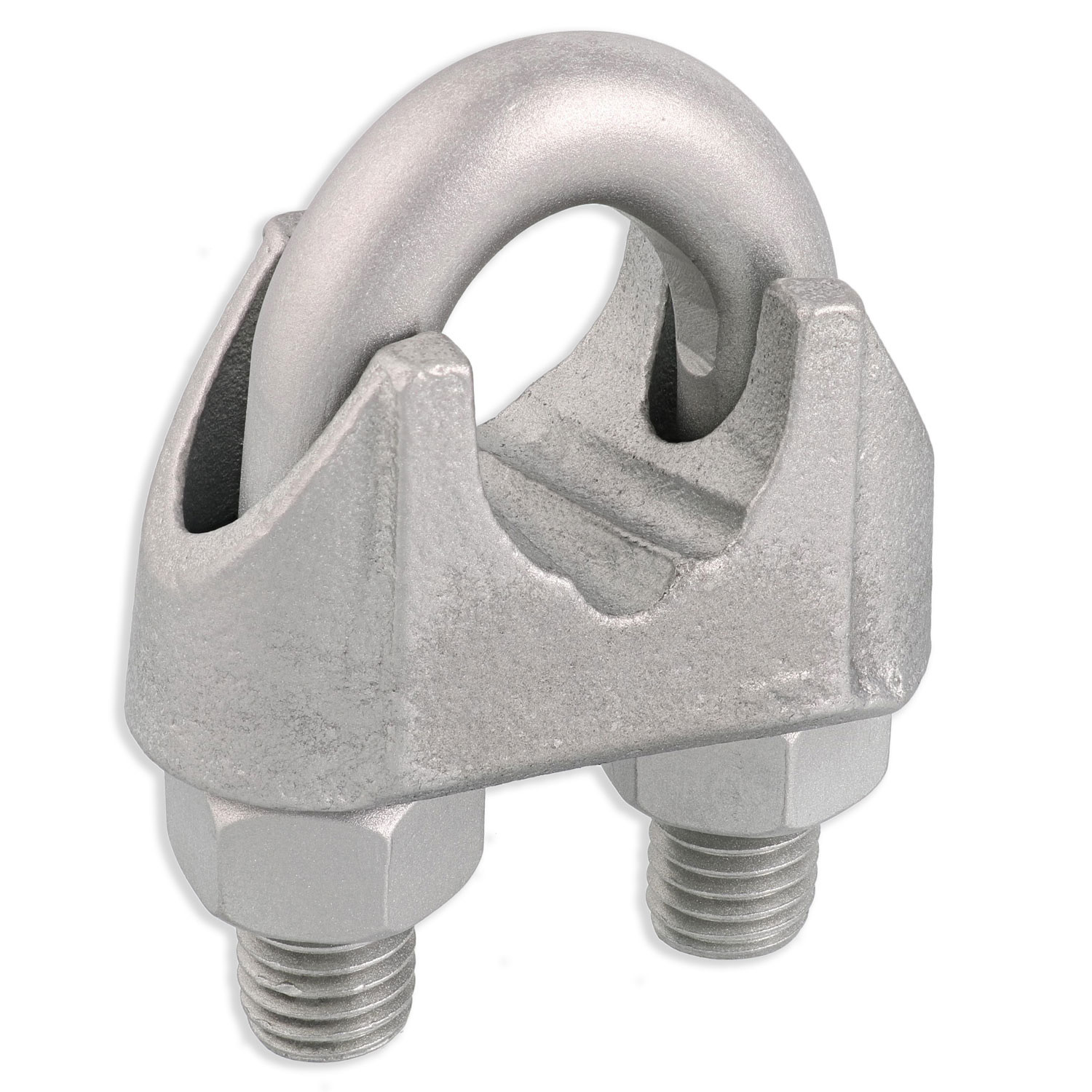
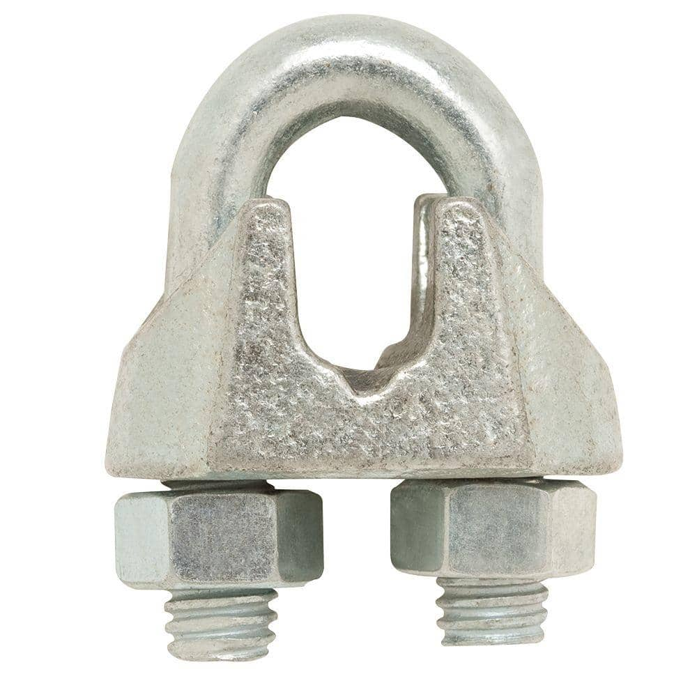
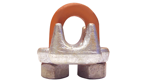
A wire rope clip, sometimes called a clamp, is used to fix the loose end of the loop back to the wire rope. It usually consists of a U-bolt, a forged saddle, and two nuts. The two layers of wire rope are placed in the U-bolt. The saddle is then fitted to the bolt over the ropes (the saddle includes two holes to fit to the U-bolt). The nuts secure the arrangement in place. Two or more clips are usually used to terminate a wire rope depending on the diameter. As many as eight may be needed for a 2 in (50.8 mm) diameter rope.
The mnemonic "never saddle a dead horse" means that when installing clips, the saddle portion of the assembly is placed on the load-bearing or "live" side, not on the non-load-bearing or "dead" side of the cable. This is to protect the live or stress-bearing end of the rope against crushing and abuse. The flat bearing seat and extended prongs of the body are designed to protect the rope and are always placed against the live end.
The ends of individual strands of this eye splice used aboard a cargo ship are served with natural fiber cord after splicing to help protect seamens" hands when handling.
An eye splice may be used to terminate the loose end of a wire rope when forming a loop. The strands of the end of a wire rope are unwound a certain distance, then bent around so that the end of the unwrapped length forms an eye. The unwrapped strands are then plaited back into the wire rope, forming the loop, or an eye, called an eye splice.
A Flemish eye, or Dutch Splice, involves unwrapping three strands (the strands need to be next to each other, not alternates) of the wire and keeping them off to one side. The remaining strands are bent around, until the end of the wire meets the "V" where the unwrapping finished, to form the eye. The strands kept to one side are now re-wrapped by wrapping from the end of the wire back to the "V" of the eye. These strands are effectively rewrapped along the wire in the opposite direction to their original lay. When this type of rope splice is used specifically on wire rope, it is called a "Molly Hogan", and, by some, a "Dutch" eye instead of a "Flemish" eye.
Swaging is a method of wire rope termination that refers to the installation technique. The purpose of swaging wire rope fittings is to connect two wire rope ends together, or to otherwise terminate one end of wire rope to something else. A mechanical or hydraulic swager is used to compress and deform the fitting, creating a permanent connection. Threaded studs, ferrules, sockets, and sleeves are examples of different swaged terminations.
A wedge socket termination is useful when the fitting needs to be replaced frequently. For example, if the end of a wire rope is in a high-wear region, the rope may be periodically trimmed, requiring the termination hardware to be removed and reapplied. An example of this is on the ends of the drag ropes on a dragline. The end loop of the wire rope enters a tapered opening in the socket, wrapped around a separate component called the wedge. The arrangement is knocked in place, and load gradually eased onto the rope. As the load increases on the wire rope, the wedge become more secure, gripping the rope tighter.
Poured sockets are used to make a high strength, permanent termination; they are created by inserting the wire rope into the narrow end of a conical cavity which is oriented in-line with the intended direction of strain. The individual wires are splayed out inside the cone or "capel", and the cone is then filled with molten lead-antimony-tin (Pb80Sb15Sn5) solder or "white metal capping",zincpolyester resin compound.
Koetsier,Teun; Ceccarelli, Marc (2012). Explorations in the History of Machines and Mechanisms. Springer Publishing. p. 388. ISBN 9789400741324. Archived from the original on 31 March 2017. Retrieved 9 April 2014.
Donald Sayenga. "Modern History of Wire Rope". History of the Atlantic Cable & Submarine Telegraphy (atlantic-cable.com). Archived from the original on 3 February 2014. Retrieved 9 April 2014.
Re: Wire rope clips on suspension scaffolds; safety latches on large crane hooks; hanging scaffolds - order of assembly; jobsite fabricated lifting accessories - criteria; and horizontal lifelines: use of wire rope clips, anchorages, number of persons allowed to be connected, requirements relating to sag, and use of synthetic rope.
This is in response to your facsimile dated November 14, 2003, to the Occupational Safety and Health Administration (OSHA). We have paraphrased your questions as follows:
Question 1(a) - (c): When using horizontal lifelines as part of personal fall arrest systems, what type of wire rope clips does OSHA require, and how many clips must be used? Additionally, what are the horizontal spacing criteria for the uprights?
Subpart M - Fall Protection, 29 CFR 1926.502, contains criteria requirements for fall protection systems. Horizontal lifelines may be used as part of a personal fall arrest system if provisions within §1926.502(d) are met. Section 1926.502(d)(8) requires that:
Horizontal lifelines shall be designed, installed, and used, under the supervision of a qualified person, as part of a complete personal fall arrest system, which maintains a safety factor of at least two.
Subpart M does not specify what type of wire rope clip or how many clips/clamps must be used when installing a horizontal lifeline. However, under §1926.502(d)(8), these decisions must be made under the supervision of a qualified person when the system is designed. The determination of the horizontal spacing criteria for uprights is also left to the qualified person"s supervisory approval.1
In an August 28, 2000 letter to Mr. Troxell2, we addressed the related issue of using wire rope clips on a wire rope guardrail. In that letter, we cautioned that, as a practical matter, it is unlikely that the criteria requirements for guardrails under §1926.502(b) could be met unless the manufacturer"s recommendations for the number of clips to be used on wire ropes of different diameters were followed (for example, the Crosby Group, Inc., general catalog 2000 edition, has tables showing their recommendations for their clips). We also pointed out that OSHA"s standard for rigging equipment used for material handling, 29 CFR 1926.251, has a table showing the number of clips required for wire rope ½-inch and greater. We noted that although that standard does not apply to wire rope used for guardrails, when designing a rope system to meet the §1926.502 guardrail requirements, following the tables at §1926.251 will normally ensure that there will be enough clips.
The forces exerted on a horizontal lifeline are substantially greater than those on a typical guardrail. Therefore, the system designer needs to ensure that the number, type, and location of clips will withstand the anticipated forces and meet the performance requirements in §1926.502 for horizontal lifelines.
The standard does not set a limit on the number of people that may be simultaneously attached to the same horizontal lifeline. Under §1926.502(d)(8), the determination of how many people may be simultaneously attached depends on a variety of factors that a qualified person must consider when designing the system.3
Extreme care should be taken in considering a horizontal lifeline for multiple tie-offs. The reason for this is that in multiple tie-offs to a horizontal lifeline, if one employee falls, the movement of the falling employee and the horizontal lifeline during arrest of the fall may cause other employees to fall also. Horizontal lifeline and anchorage strength should be increased for each additional employee to be tied-off. For these and other reasons, the design of systems using horizontal lifelines must only be done by qualified persons.
Although the possibility of one person falling may raise the risk of another person being pulled into a fall, it is not our position that the lifeline must necessarily be designed so that it can withstand a simultaneous fall by all the individuals tied-off to it. In assessing the total strength required for the lifeline, the qualified person must make a determination on the likelihood of simultaneous falls based on factors such as the type of walking/working surface the workers will be on, the length of their lanyards, and whether their work assignments call for them all to be near the edge at the same time.
Anchor points for a horizontal lifeline must be determined under the supervision of a qualified person under §1926.502(d)(8). Subpart M does not identify particular anchor points for horizontal lifelines. Appendix C, Section II (h)(1), provides some anchorage point considerations to be addressed when designing personal fall arrest systems.
Question 2: For a horizontal lifeline used as part of a personal fall arrest system during steel erection work, how tight should the lifeline be, and may synthetic rope be used for the horizontal lifeline?
Subpart R - Steel Erection, 29 CFR 1926.760, addresses fall protection requirements in steel erection. Section 1926.760(d), criteria for fall protection equipment, incorporates into Subpart M §1926.502(b)-(e), fall protection systems criteria and practices. Section 1926.502(d)(8) requires that:
Horizontal lifelines shall be designed, installed, and used, under the supervision of a qualified person, as part of a complete personal fall arrest system, which maintains a safety factor of at least two.
Therefore, a qualified person is required to determine how tight the lifeline should be based on site-specific factors. No other requirements are imposed by OSHA regarding the tightness of the lifeline, so long as it comports with a safety factor of at least two.
With regard to the use of synthetic ropes, §1926.502(d)(14) specifies that, when using non-wire rope, synthetic rope (rather than nature fiber rope) must be used:
Scaffolds shall be designed by a qualified person and shall be constructed and loaded in accordance with that design. Non-mandatory Appendix A to this subpart contains examples of criteria that will enable an employer to comply with paragraph (a). [Emphasis added.]
Qualified means one who, by possession of a recognized degree, certificate, or professional standing, or by extensive knowledge, training, and experience, has successfully demonstrated his/her ability to solve or resolve problems related to the subject matter, the work, or the project.
The employer is responsible for designing and assembling components in such a way that the completed system will meet the requirements of §1926.451(a). Scaffold components which are not selected and loaded in accordance with this Appendix, and components for which no specific guidelines or tables are given in this Appendix, must be designed and constructed in accordance with the capacity requirements of §1926.451(a).
The requirements set forth in §1926.451(b) must also be followed when erecting the scaffold. In regard to scaffold components used in the construction of the scaffold, §1926.451(b)(10) states:
Scaffold components manufactured by different manufacturers shall not be intermixed unless the components fit together without force and the scaffold"s structural integrity is maintained by the user. Scaffold components manufactured by different manufacturers shall not be modified in order to intermix them unless a competent person determines the resulting scaffold is structurally sound. [Emphasis added.]
Section 1926.451(f) sets out requirements involving the use of the scaffold. Where scaffolding is erected, moved, dismantled, or altered, §1926.451(f)(7) provides:
Scaffolds shall be erected, moved, dismantled, or altered only under the supervision and direction of a competent person qualified in scaffold erection, moving, dismantling, or alteration. Such activities shall be performed only by experienced and trained employees selected for such work by the competent person. [Emphasis added.]
Competent person means one who is capable of identifying existing and predictable hazards in the surroundings or working conditions which are unsanitary, hazardous, or dangerous to employees, and who has authorization to take prompt corrective measures to eliminate them.
When erecting the scaffold you describe, the employer must ensure that the scaffold has been designed by a qualified person and constructed and loaded in accordance with that design. If the designer requires the scaffold to be erected from the top down, then it must be erected in that manner. If the designer requires it to be erected from the bottom up, then that order must be followed. If the designer does not indicate one or the other order, then the competent person must determine whether the scaffold may be erected from the top down or the bottom up.
Question 4: Are there OSHA standards that specify criteria for constructing jobsite fabricated rigging equipment such as an equalizing beam, lifting beam, spreader beam, equalizing plates, tee lugs, lifting lugs, and welded scaffold brackets?
The only OSHA construction standards that contains specific criteria related to the construction of special custom design lifting accessories is 29 CFR 1926.251(a)(4), which states:
(4) Special custom design grabs, hooks, clamps, or other lifting accessories, for such units as modular panels, prefabricated structures and similar materials, shall be marked to indicate the safe working loads and shall be proof-tested prior to use to 125 percent of their rated load.
Question 5: Under §1926.451(d)(12)(v) and (vi), when wire rope clips are used on suspension scaffolds, "(v) U-bolt clips shall not be used at the point of suspension for any scaffold hoist," and "(vi) when U-bolt clips are used, the U-bolt shall be placed over the dead end of the rope, and the saddle shall be placed over the live end of the rope." Does §1926.451(d)(12)(v) contradict paragraph (d)(12)(vi)?
No. By its terms, §1926.451(d)(12)(v) prohibits the use of U-bolt clips at the point of suspension for any scaffold. The scaffold standard does not prohibit using U-bolt clips elsewhere. However, when using them elsewhere, under §1926.451(d)(12)(vi), the U-bolt must be placed over the dead end of the rope, and the saddle placed over the live end of the rope.
Question 6: Under §1926.251(c)(4)(iii), are eyes in wire rope bridles and slings or bull wires formed by wire rope clips permitted when used to lift scrap boxes or pendants?
This provision specifically prohibits eyes in wire rope bridles and slings or bull wires being formed by wire rope clips. There is no exception for lifting scrap boxes or pendants.
There are no OSHA standards setting criteria for horizontal high-lines. However, an employer"s use of a horizontal high-line must be in accordance with its obligations under Section 5(a)(1) of the Occupational Safety and Health Act (the "General Duty Clause"), which states:
Each employer shall furnish to each of his employees employment and a place of employment and a place of employment which are free from recognized hazards that are causing or are likely to cause death or serious physical harm to his employees.
In our view, the industry recognizes that the following engineering factors, among others, must be considered when designing horizontal high-lines: the span and sag of the wire rope line, the weight of the load being lifted, the initial tension of the rope line, and the size of the columns.
OSHA requirements for a safety latch on hooks do not depend of the size of the hook but rather the activity for which the hook is being used. Safety latches on hooks are required in two instances:
Hooks on overhaul ball assemblies, lower load blocks, or other attachment assemblies shall be of a type that can be closed and locked, eliminating the hook throat opening. Alternatively, an alloy anchor type shackle with a bolt, nut and retaining pin may be used.
Section 1926.753(d) prohibits workers engaged in steel erection activities from being directly under a suspended load, with some exceptions. Where those exceptions apply (i.e., where workers are engaged in the initial connection of steel or employees are unhooking the load), specific criteria apply. One such criterion is the requirement for safety latches.
This provision was intended to prevent the components from becoming accidentally unfastened from the hook and falling on the worker below. The preamble to the proposed rule explained that an "equivalent" device would include:
A hook with another type of closing device, i.e., a hook with a spring-loaded gate or another type of safety hook that would provide the same level of safety as a safety hook with a self-closing latch. (At 63 FR 43464, August 13, 1998.)
Neither the personnel platform nor the steel erection/working under load requirement has an exception for large hooks - the requirements apply irrespective of the size of the hook. Also, there is no "grandfather" exception for older hooks without safety latches.
Knotting wire rope compromises the integrity of the strength of the wire rope and is therefore prohibited. Based on the picture provided, which showed a knot in wire rope secured by a U-bolt clip, this practice would be in violation of §1926.251(c)(3).
Question 10: Do OSHA standards require the attachment of an orange and white flag to the highest point of a crane that is being used in the vicinity of an airport?
There are no OSHA standards that require the highest point of a crane to be marked to enhance visibility to air traffic. However, the use of a crane in the vicinity of an airport may be subject to requirements set by other regulatory agencies, such as the Federal Aviation Administration.
Question 11: Do OSHA standards specify a particular anchorage point for connecting the lanyards of workers on crane suspended personnel platforms? Do the standards limit the number of such workers that can be attached to an anchorage point?
This standard applies to the design [and]* * * use of personnel platforms on the load lines of cranes or derricks and the hoisting of personnel platforms on the load lines of cranes or derricks.
Except over water, employees occupying the personnel platform shall use a body belt/harness system with lanyard appropriately attached to the lower load block or overhaul ball, or to a structural member within the personnel platform capable of supporting a fall impact for employees using the anchorage. When working over water, the requirements of §1926.106 shall apply. [Emphasis added.]
Anchorages used for attachment of personal fall arrest equipment shall be independent of any anchorage being used to support or suspend platforms and capable of supporting at least 5,000 pounds * * * per employee attached or shall be designed, installed, and used as follows: (i) as part of a complete personal fall arrest system which maintains a safety factor of at least two; and (ii) under the supervision of a qualified person.
As you can see from the text of these provisions, §1926.550(g)(6)(vii) specifies the permissible locations of anchorage points - lower load block, overhaul ball, or the structural member within the personnel platform. Section 1926.502(d)(15) in Subpart M sets forth various criteria for anchorage points but does not establish a limit relative to the number of workers that can be attached to any one anchorage.
In addition, note that several other significant provisions in §1926.550(g) of Subpart N may affect the number of employees allowed in a personnel platform. These provisions include §1926.550(g)(4), which limits the number of employees on platforms to those required to do the work, and sets other requirements as well. Provisions most relevant to your question include §1926.550(g)(3)(i)(E) (limits total weight of loaded personnel platform and related rigging to 50 percent of rated capacity for the radius and configuration of the crane); §1926.550(g)(3)(i)(B) (load line capacities); §1926.550(g)(4)(i)(C) (support criteria applicable to the personnel platform itself); §1926.550(g)(4)(iii) (load limitation of the personnel platform); and §1926.550(g)(4)(iii)(C) (personnel platform rigging requirements). Note that this list is not comprehensive -- please see the actual text of §1926.550(g) for the other provisions.
If you need additional information, please contact us by fax (202-693-1689) at: U.S. Department of Labor, OSHA, Office of Construction Standards and Guidance. You can also contact us by mail at U.S. Department of Labor, OSHA, Office of Construction Standards and Guidance, Room N3468, 200 Constitution Avenue, N.W., Washington, D.C. 20210, although there will be a delay in our receiving correspondence by mail.
1Note that Appendix C to Subpart M provides Non-Mandatory Guidelines for complying with §1926.502(d), personal fall arrest systems, and provides some information on the design of horizontal lifelines. [ back to text ]
Anchorages used for attachment of personal fall arrest equipment shall be . . . capable of supporting at least 5,000 pounds per employee attached or shall be designed, installed, and used as follows: (i) as part of a complete personal fall arrest system which maintains a safety factor of at least two;

Wire ropes are one of the most critical pieces of rigging and lifting hardware. You can use wire ropes for lifting, rigging, and tying loads of virtually any size, shape, and type. To make the most out of wire ropes, however, you need a few additional rigging equipment, one of which includes wire rope clamps.
Also known as wire rope clips, riggers often use this nifty little piece of hardware at the end of the length of a wire rope. You can use a wire rope clamp to:
In short, a cable clamp is what makes a wire rope one of the most versatile pieces of rigging hardware. As these clamps come in different shapes, sizes, and materials, you will need to choose one that perfectly fits your lifting and rigging application. But before we get down to that, first, you need to understand what is wire rope clamp, its types, and a few other things.
It is a simple mechanical device. A typical wire rope clip consists of a saddle, U-bolt, and two hex nuts. This simple device is suitable for less permanent rigging and lifting applications. You must never use wire rope clips to make industrial slings.
The ASME B30.9 Slings standard clearly states that riggers should not use mechanical wire rope terminations that require periodic adjustments to create slings. In other words, you need to be careful when using rope clamps. You can use a wire rope clip to create an end loop for a winching or crane cable. You can also use it to build perimeter cables or increase the length of a wire rope going through a D-shackle or eye bolt.
Based on their shape, there are two types of cable clamps, U-bolt and double saddle. They both have unique mechanical properties and hence applications.
These cable clamps consist of a U-bolt, two nuts, and a metal base called a saddle. The U-bold passes through the saddle, which you can tighten with the two nuts. They come in various sizes and types of materials, including stainless steel and galvanized steel. You can choose a U-bolt wire rope clamp depending on your rigging or lifting application.
These claps consist of two saddles with one leg each and two nuts. As the saddles are mirrored, they can fit into each other without a bolt. This unique design also means you can use these in either direction, which makes them more user-friendly.
Usually, there are three types of materials used for making rope clips. You can choose a material based on your application as each one comes with its unique strengths and weaknesses.
In this type of wire rope clip, the base or saddle is made from forged steel. The manufacturing process involves heating and hammering the clips into desired shapes. Riggers often use these cable clamps for critical and heavy-duty applications as they are very strong. You can see them in winch lines, crane cables, hoist lines, towing lines, scaffoldings, guy lines, and even tie-downs.
The base or saddle is made from cast iron. As cast iron lacks the metal properties of stainless steel, it is not that strong. So, the malleable galvanized wire rope clamps are not very strong. They can break under heavy usage. You will see them being used in small or light-duty applications like fencing, parameter cables, or guard rails.
Stainless steel wire rope clips are arguably the best ones. The base or saddle is made from high tensile strength stainless steel. They are durable and easy to use. You can find these cable clamps in temporary guard rails, flag posts, and other outdoor rigging applications.
Wire rope clamps are an essential part of the rigging hardware. You can’t do away with them. But you have to make sure to use the right ones to keep the load and the riggers safe. If a wire rope snaps because you used the wrong type of clip, it can lead to disastrous consequences.
The first step in choosing cable clamps is to buy them from a trusted and reputed rigging hardware manufacturer. The last thing you want is to use a defective or poor-quality clip. This will compromise the safety of your load and your crew.
As you can see, each wire rope clamp comes with unique properties. You need the instruction manual to understand when, where, and how to use the cable clamps. Make sure the clamps are accompanied by respective user manuals when making a purchase.
By now, you know that some cable clamps are more suited for outdoor environments, while others aren’t. As a result, carefully think about where you want to use the wire rope clips. For example, if it’s a heavy outdoor application, stainless steel wire rope clamps would be a great fit.
Taking into account how large and heavy the load is also equally important. Heavier loads will require strong cable clamps that won’t break under stress. Also, you shouldn’t use clips for any permanent rigging or lifting applications. They are suited only for temporary load applications.
Lastly, it’s always better to get an expert on board when shopping for wire rope clips. Maybe you can hire an engineer or expert with considerable field experience to help you choose the right types of clamps. An expert will help you take every detail into account before making the purchase. Remember, if you choose the right cable clamps right off the bat, you’ll save considerable time and money down the line.
Wire rope clamps are one of the essential rigging hardware. They land wire ropes more flexibility, allowing you to handle a wide range of applications with ease and safety. These are some tips that will help you choose the appropriate clamp for your need.
HHI sells different types of clamps and other rigging hardware, both online and offline. If you are looking for reasonably priced and high-quality cable clamps or other hardware, check out our online store or reach out to our experts.


 8613371530291