
valley breaks wire rope manufacturer
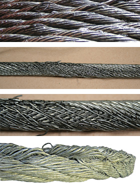
Example: Severe crown wire breaks on a 10-strand overhead crane wire rope. Crown breaks originate at the OUTSIDE of the rope at the contact point between rope and sheave/drum.
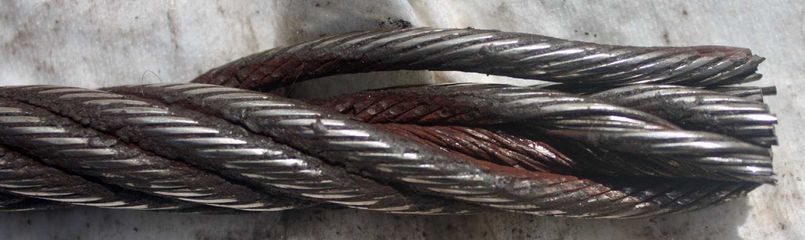
Remove the rope from service even if you find a SINGLE individual wire break which originates from inside of the rope. These so called VALLEY breaks have shown to be the cause for unexpected complete rope failures.
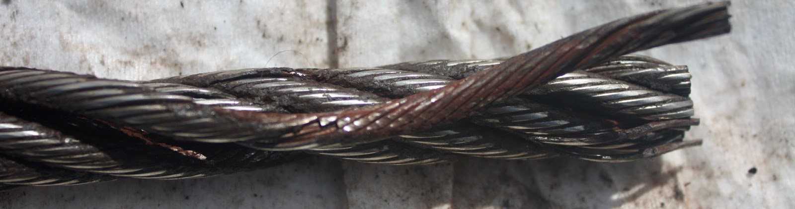
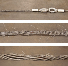
These 3 picture show what happens when you connect a left-lay rope to a right-lay rope, as done with this boom pendant extension. Both ropes are opening up to the point where the strands are nearly parallel to each other; they completely untwisted themselves and developed excessive wire breaks.
The result of such non-tensioning of the layers are looping of individual wires, completely crushed strands, total deterioration of a non-rotating rope due to gross neglect of inspection procedure.
NOTE: For a more indepth discussion on wire rope discard and inspection we suggest to attend our “Wire Rope” and “SlingMax® Rigger’s Mortis Seminar”. Call 1.800.457.9997 for details and dates.
Like all industrial equipment, aircraft cables and wire ropes wear while in service, and will require replacement. Though the cycle life of each cable varies based on construction and application, factors such as load and pulley condition can actually reduce this lifespan by triggering wire breaks. Not all wire breaks look the same, and understanding these differences can help detect issues in your system before they damage additional cables, or put human lives in danger. Here is a quick guide to help you understand where wire breaks occur (crowns vs. valleys), and three common examples of wire breaks (tension, fatigue, and abrasion).
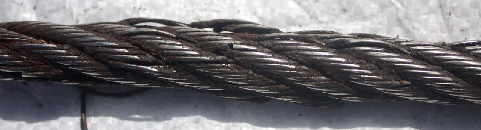
Wire breaks typically occur in two different locations on the outside of wire rope or aircraft cable. The first location is on the crowns of the strands, which are the highest points with the most surface area exposure. The second location is the valleys, or the spaces between the strands. Though crown breaks typically result from normal wear and tear, valley breaks are more suspicious and may indicate issues with the pulley system or wire rope itself.
Wires that have been worn to a knife-edge thinness are characteristic of abrasion breaks. Abrasion can occur from a number of different sources, but sheaves are the most common. Remember to check sheaves for signs of wear, damage, or deformity and replace as necessary.
If you notice one end of a broken wire is cupped, and the other end resembles a cone, your wire rope likely experienced a tension break. Tension breaks result from excessive loading, causing the wires to stretch beyond their limits until they snap. Once one wire break appears, others will continue to occur if the cable is not addressed.
Fatigue damage is usually represented by zig-zag breaks with square ends. Like abrasion breaks, fatigue breaks can be triggered by a broad range of factors, including incorrect pulley size and excessive vibration. Check for worn pulleys and slack in the system to prevent issues from exacerbating.
Once you have replaced your damaged pulleys, or removed sharp obstructions in your system, begin your quote for brand new wire rope at https://strandcore.com/contact/. Our wire rope craftsmen can help you select the ideal wire rope for your application, and oftentimes provide a better solution for your existing setup. Browse our selection ofwire rope and aircraft cableonline, and do not hesitate to contact our sales team at sales@sanlo.com if you have any questions.
All wire ropes will wear out eventually and gradually lose work capability throughout their service life. That"s why periodic inspections are critical. Applicable industry standards such as ASME B30.2 for overhead and gantry cranes or federal regulations such as OSHA refer to specific inspection criteria for varied applications.
You should thoroughly inspect all wire ropes at regular intervals. The longer it has been in service or, the more severe the service, the more thoroughly and frequently it should be inspected. Be sure to maintain records of each inspection.
Inspections should be carried out by a person who has learned through specialized training or practical experience of what to look for and who knows how to judge the importance of any abnormal conditions they may discover. It is the inspector"s responsibility to obtain and follow the proper inspection criteria for each application inspected.
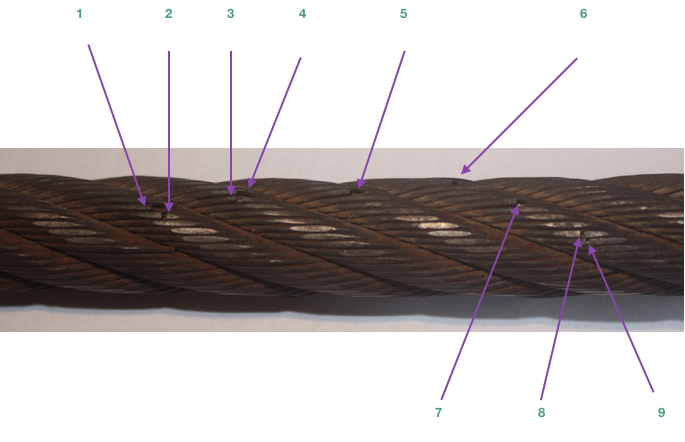
Figure 1is what happens when a wire breaks under tensile load exceeding its strength. It"s typically recognized by the "cup and cone" appearance at the point of failure. The necking down of the wire at the point of failure to form the cup and cone indicates failure has occurred while the wire retained its ductility (the ability to change form without breaking).
Figure 2is a wire with a clear fatigue break. It is identified by the square end perpendicular to the wire. This break was produced by a torsion machine that"s used to measure the ductility. This break is similar to wire failures in the field caused by fatigue.
Figure 3 is a wire rope that has been subjected to repeated bending over sheaves under typical loads. This fatigue results in breaks in individual wires - these breaks are square and usually in the crown of the strands.
Figure 4 is an example of fatigue failure of a wire rope subjected to heavy loads over small sheaves. The breaks in the valleys of the strands are caused by "strand nicking." There may be crown breaks, too.
Figure 5 is a single strand removed from a wire rope subjected to "strand nicking." This condition is a result of adjacent strands rubbing against one another. While this is normal in a rope"s operation, the nicking can be accentuated by high loads, small sheaves or loss of core support. The ultimate result will be individual wire breaks in the valleys of the strands.
Reeving failures have been a leading cause of accidents in our trade. They were thirty years ago when Wilbert A Lucht wrote his article, “Sheave Design vs Wire Rope Life” (reprinted in the June issue ofWire Rope News, page 26), and are still today.
A Crane is a combination of two simple machines. One is a lever, and the other is a block and tackle. Both increase the machinal advantage of a crane’s lifting capability. However, the block and tackle (sheaves and wire rope, referred to as reeving) are “used-up” as the crane works.
The sheave differs from a “pulley” or roller importantly. Both change the direction of the rope and increase the mechanical advantage — pulling power. However, the sophisticated sheave does the same but also maintains the cross-section shape of the rope, critical to reducing wear, and the rope strength — if properly sized.
A Sheave gauge is being used to check the groove size by a crane inspector in Fig. 1. These gauges have the maximum size of the groove recommended for the rope that is installed on the crane.
An oversize or worn-out sheave acts just like a pulley, not preserving the rope’s shape, Fig. 2. Instead of the load being supported by at least three strands at the bottom of the groove, all the load is concentrated on one. With less support, increased pressure equals more significant sheave wear. There is another terrible consequence of improper groove support — premature wire breaks and internal wire wear. When the unsupported rope is bent over a sheave and loaded, the strands must adjust by sliding along each other. Sliding causes strand to strand nicking and “valley” wire breaks, a severe reduction in the rope’s life, Fig. 3.
The consequence of sheaves not correctly sized to the wire rope installed on them is accelerated wear and broken wires. How important is this to the crane owner depends on how many hours of operation per inspection interval. Some cranes aren’t used much, and owners aren’t too concerned with groove size, just so the grooves are “kind of” smooth — wrong. Current standards allow only one valley break, as shown in Fig.3.
The point is, to achieve a predictable rope life — the sheave must support about 150 degrees of the rope at the bottom of the groove, or the rope will flatten when loaded and be weaken — got that!
You may not know that most areas of your wire rope will be in perfect working condition while some areas are at the point of replacement. The points that require replacement are the parts of the wire rope that bend over a sheave or, during drilling, winds into a drum.
On drill rigs, loads are applied to a winch, and either a rod, piece of casing at a table, or a rod box or rack are picked up. Because of this, the same length of rope will move over the sheave and enter the drum each time an operator applies a load.
Wire rope wears faster if it is subjected to bending. Bending causes the outer wires and inner wires travel at different speeds. Also, loading a wire rope while it’s bending will increase the stress.
The first type of method utilizes a glove or rag. The rag or glove will fully cover your hand while you lightly grasp the wire rope as it moves at a slow speed. Broken wires on the external will stick out, causing it to snag the glove or rag. The rope will be stopped and the inspector will assess the rope’s condition. If a problem is found, the inspector will mark the rope at the concerned location.
Another method is the visual-only inspection. In this method, you move the rope 2 to 3 feet and stop to inspect the rope on all sides visually. In areas where grease/grime may cover the rope, clean it with a wire rope because defects may be hiding underneath.
While visually inspecting the rope, bend it to look for “valley breaks.” These are breaks that happen where the strands come in contact with each other. These breaks may be difficult to see without the rope being bent.
Valley breaks typically happen in rope applications that involve small diameter sheaves or sheave grooves that are too small carrying heavy loads. Also, keep an eye out for the areas of the rope that come in contact with drums and sheaves when they pick up loads.
While inspecting wire rope, also be on the lookout for a reduction in diameter. This helps determine the stability of the rope’s core. Two numbers are given upon installation of the rope: the diameter and the length of the rope.
To perform this inspection, place a caliper on the rope’s widest point to read the diameter. Wire ropes are manufactured larger than nominal diameter. When ropes are placed in service their diameter may have a slight reduction. In this case, make the initial measurement of a rope diameter after its first load. A rope should be removed from service if its diameter falls to 95% of its nominal diameter.
A rope’s overall length is just as crucial in determining its health as the diameter. When a core starts to fail, the length of the rope will increase. All increases in rope length are means for replacement.
When going through any regular inspection, make sure you are lubricating your wire rope. A wire rope is lubricated during manufacturing, but this initial lubrication is not enough to last the rope’s lifetime.
Lubrication is crucial and is sure to clean and dry the wire rope before applying. Actual lubrication only occurs when the lubricant encounters bare wires. Wire ropes that are used under working conditions should have a lubricant for cable oil. Do not use PB blaster, WD-40, or any crankcase oil.
Silver State Wire Rope and Rigging Inc.is the only company of its kind in Nevada. We have several divisions and expertise in each field. If you have any concerns or questions about your wire rope or need more,call us!We’re happy to answer your questions and inquiries!

break. When using this criterion, an inspector is looking for the number of total crown wire breaks within a rope lay. A rope lay is approximately 6.5 times the diameter of the rope. For example, the rope lay
(a) if the broken wires are equally distributed among the strands, when the number of broken wires per rope lay in the worst section of the rope exceeds the values shown in column A of Table 8.11.2.1.3(cc)(1); or
(b) if the distribution of the broken wires is unequal, and broken wires predominate in one or two strands, when the number of broken wires per rope lay in the worst section of the rope exceeds the values shown in column B of Table 8.11.2.1.3(cc)(1); or
(c) if four or five wires, side by side, are broken across the crown of any strand, when the number of broken wires per rope lay in the worst section of rope exceeds values shown in column C of Table 8.11.2.1.3(cc)(1); or
(d) if in the judgment of the inspector, any unfavorable condition, such as fretting corrosion (red dust or rouge), excessive wear of individual wires in the strands, unequal tension, poor sheave grooves, etc., exists, the criteria for broken wires will be reduced by 50% of the values indicated in Table 8.11.2.1.3(cc)(1) for any of the three conditions described above; or
(a) if the broken wires are equally distributed among the strands, when the number of broken wires per rope lay in the worst section of rope exceeds 12 to 18; or
(c) When replacing suspension, compensating, and car or drum counterweight ropes, all ropes in a set shall be replaced, except as permitted by 8.6.3.2. (d) The ropes in the set shall be new, all from the same manufacturer, and of the same material, grade, construction, and diameter.
wires in the strands, unequal tension, poor sheave grooves; the criteria for broken crown wires shall be the values indicated in the “Unfavorable Wear Conditions,” second column of Table 1.10.1.2-1 for any of the conditions described above
(e) if red dust or rouge exists, the criteria for broken wires shall be the values indicated in the “Rope Showing Rouge,” third column of Table 1.10.1.2-1 for any of the conditions described above
1.10.1.2.1 The elevator manufacturer using information from the rope manufacturer and considering the application, shall establish the design life limit to ensure that the residual strength of wire ropes less than 8 mm (0.315 in.) diameter is not less than 60% of the minimum breaking force at the time of replacement.
(b) For rope diameters equal to or greater than 8 mm (0.315 in.), the ropes shall be replaced in accordance with 1.10.1.2(a) through 1.10.1.2(g) and 1.10.3.
(c) For rope diameters less than 8 mm (0.315 in.), the ropes shall be replaced in accordance with 1.10.1.2(a) through (g), 1.10.1.2.1 and 1.10.1.2.2, and 1.10.3. In addition, other replacement criteria based on the application shall be permitted to be applied. The replacement criteria shall be documented in the Maintenance Control Program (see ASME A17.1/CSA B44, requirement 8.6.1.4.1).
(a) if the broken crown wires are equally distributed among the strands, when the number of broken wires per rope lay in the worst section of rope exceeds the values shown in the “Normal Wear Conditions,” first column of Table 1.10.1.2-1
(b) if the distribution of breaks is unequal and broken crown wires predominate in one or two strands, when the number of broken wires per rope lay in the worst section of rope or the minimum diameter exceeds the values shown in the “Normal Wear Conditions,” first column of Table 1.10.1.2-1
(c) if four wires, side by side, are broken across the crown of any strand, when the number of broken wires per rope lay in the worst section of rope exceeds the values shown in the “Normal Wear Conditions,” first column of Table 1.10.1.2-1
(a) the broken crown wires are equally distributed among the strands, when the number of broken wires per rope lay in the worst section of rope exceeds 12;
Plastic-infused rope was developed to provide better fatigue, abrasion and crushing resistance derived from the cushioning and dampening effect of the plastic. However great the benefits, the plastic becomes at the very least, an inconvenience when trying to inspect the wire rope. Because of the plastic coating, some operators choose to forego inspection and run the ropes to failure. Other operators may just visually inspect the plastic coating. Both practices are wrong and carry equally the potential for disaster.
AbrasionandCrushing.In inspecting plastic-infused ropes, the basic inspection guidelines still apply and should be followed. Abrasion and crushing damage still may occur, so it is imperative to inspect flanges, sheaves, bearings, rollers and fairleads. Look for unusual wear patterns in the plastic—a key indicator that damage to the wire rope is occurring.
WireBreaks.Wire breaks still will occur in a plastic-infused rope, but are sometimes extremely difficult to detect, though occasionally a broken wire will protrude through the plastic. Every effort must be made to determine the overall condition of the rope. The plastic covering the crown (surface) wires is generally applied in a thin coat and tends to wear quickly in areas which pass over sheaves and drums. As the rope runs at a slow speed, inspect the rope in these areas. As the rope and plastic open up, the inspector will be afforded a look at not only the surface area but also the interstrand contact points. If a valley break is detected, immediately pull the rope from service. Also inspect areas where the plastic has peeled, regardless of the location of the “window.” Remove as much plastic from these areas as possible to allow for efficient and effective inspection techniques. Remember, due to the nature of plastic-infused ropes, there is no way to clearly determine the number of valley breaks.
Corrosion.Plastic-infused ropes provide only improved corrosion resistance. Regardless of manufacturers’ claims, a plastic-infused rope can corrode, and rope failure due to corrosion is still possible. Moisture is sometimes trapped in the rope and, as with all machines the lubricant may become ineffective over time. The inspector must visually check for any signs of corrosion damage as evidenced by rope bleeding or rouging. In addition, the diameter must be measured frequently. If there is any damage to the core, it will be detected by a reduction in diameter. Also inspect the lay of the rope. As the plastic is thinner over the crown wires, a thorough inspector may be able to determine a lengthening of lay, also a sign of rope deterioration. Especially when trying to determine lengthening of lay, watch for and inspect areas where the plastic pulls away from the rope. While peeling in and of itself is not an indication of rope deterioration and is a factor of normal wear, peeling in areas where no abrasion exists may signify a problem.
Maintenance Records.Equally important in inspecting plastic-infused ropes is maintaining accurate service records. The service records of previous ropes will provide a guideline as to the expected life of the rope. However, they should not be used alone or only in conjunction with visual inspections due to the number of variables which exist, including installation, spooling and manufacturing practices. Maintenance records must be used in combination with both visual and physical inspection techniques to be truly of value in determining the remaining life of the rope.
Die drawn and swaged ropes fall into the compacted category. Compacting serves several purposes. By flattening the outer wires, metallic area increases allowing for a higher breaking strength as well as improved crushing and abrasion resistance. In addition, the compaction minimizes interstrand nicking and thereby improves fatigue resistance.
In the inspection of compacted rope designs, again it is imperative to follow the basic inspection guidelines and use both visual and actual measuring techniques to determine the remaining life of the rope. In fact, actual measuring techniques are very important when inspecting these ropes. While corrosion is relatively easy to visually determine, diameter reduction may not be due to the compacted rope’s appearance. Therefore, the inspector must regularly measure for diameter reduction and closely examine the rope for lay lengthening. Measurements must be recorded and the rope monitored for sudden variations.
By and large the most difficult retirement criteria to determine in compacted ropes are wire breaks. These breaks may not protrude from the rope due to the compaction and can be overlooked easily. Because of this, the inspector must slowly and carefully examine the rope, especially in those areas passing over drums and sheaves or in areas where problems existed in previous ropes.
A wire break may appear as nothing more than a crack in the wire, and again can be overlooked easily. If the inspector notes a “flaw” in a wire, it should be checked carefully. The inspector should carry some type of magnifying device to determine if a flaw is actually a break. If a break has occurred, thoroughly check the area for additional breaks, both on the crown and in the valleys. Remember, valley breaks in round strand ropes are difficult to determine; compaction only increases the difficulty. The inspector must be slow and methodical in inspecting compacted ropes; a quick check will reveal nothing.
Overall, perhaps the most important inspection technique is recognizing the limits of wire rope. While it’s true that compacted and plastic-infused ropes are more durable, neglect and abuse still will quickly end the rope’s life. There is no substitute for proper installation, handling and inspection techniques in combination with a preventative maintenance program.
Hoist cars shall be suspended by steel wire ropes attached to the car frame or passing around sheaves attached to the car frame specified in Section 1604.16.
(1) Only steel wire ropes having the commercial classification "elevator wire rope," or specifications recommended by wire rope manufacturers for hoist use, shall be used for the suspension of hoist cars or for the suspension of counterweights.
A new tag shall be installed at each rope renewal. The material and marking of the rope data tag shall conform to the requirements of Section 1604.21(d), except that the height of the letters and figures shall be not less than 1/16-inch.
The factors of safety of the suspension wire ropes shall be not less than shown in Table 5. Figure 5 gives the minimum factors of safety for intermediate rope speeds. The factor of safety shall be based on the actual rope speed corresponding to the rated speed of the car. The factor of safety shall be calculated by the following formula:S x N
NOTE: In the case of multiple roping, the number of runs of rope (N) under the load will be: twice the number of ropes used, for 2:1 roping; three times the number of ropes used, for 3:1 roping, etc.Table 5
Car suspension ropes of winding-drum machines shall have the ends of the rope secured to the drum or drum flange by means of clamps or tapered sockets or by other means approved by the enforcing authorities.
Wire suspension ropes of drum type machines shall have not less than three wraps of the rope on the drum when the car is resting on the fully compressed buffers.
Hoisting and counterweight wire ropes shall be attached to cars and counterweights by means of zinc-coated or galvanized drop forged fist grips or equal and wire rope thimbles, or by approved special fastening devices. When fist grips are used, the minimum number, spacing, and tightening torque shall be in accordance with the instructions of the grip manufacturer. Grips shall be periodically checked and retightened to the recommended torque.
When extra wire rope is carried on top of the frame of the hoisting platform, a drum and clamp tie down or equivalent type anchor device, which will not damage or deform the wire rope, shall be used.
Babbitted rope sockets shall be prohibited except on permanent passenger or freight elevators which are temporarily being used as construction personnel hoists.
(1) A representative of the user of the personnel hoist shall be appointed, and this representative shall keep written records of the rope condition on file at the work site.
(4) Examination of traction machine ropes and counterweight ropes of drum type hoists should preferably start with the car located at the top of the hoistway and should be made from the top of the car, with the ropes examined on the counterweight side.
(6) Where a traction or drum machine is located below, the portions of the ropes leading from the driving machine drum or sheave and from the counterweight to the overhead sheaves can be examined from the top of the car as it descends, except for a small portion which must be examined from the pit.
(7) The rope should be marked with chalk to indicate location of unexamined sections which must be inspected from other locations such as the pit or overhead machinery space.
(8) Sheaves, guards, guides, drums, flanges, and other surfaces contacted by wire rope during operation should be examined at the time of inspection. Any condition harmful to the rope shall be corrected.
If one wire rope of a set requires replacement, the entire set of ropes shall be replaced. Wire rope shall be removed or replaced immediately if it has one or more of the following defects:
(3) Six randomly distributed broken wires in one rope lay or three broken wires in one strand in one rope lay. (A rope lay is the length along the rope in which one strand makes a complete revolution around the rope.)
(4) Development of broken wires in the vicinity of attachments. If this condition is localized in an operating rope and the section in question can be eliminated by making a new attachment, this may be done rather than replacing the entire rope.
Governor ropes shall be replaced on the same basis as hoisting ropes. (These ropes are lightly loaded and may show little or no wear. Inspectors should check for fatigued wires in strand valleys by bending over a small radius.)

A wire rope is a type of cable that includes several wire strands laced together to form a single wire. Generally, both the terms “wire” and “rope” are used interchangeably with “wire rope”; however, according to the technical definition, to be labeled a wire rope, the cable must have a thickness of at least 9.52 mm. As a versatile, high load capacity alternative to natural fiber ropes such as hemp and manila, wire rope provides motion transmission through nearly all angles, tie down, counterbalance, guidance, control, or lift.
Modern wire rope was invented by Wilhelm Albert, a German mining engineer, between 1831 and 1834. He developed them in order for work in the mines in the Harz Mountains. This rope replaced weaker natural fiber ropes, like hemp rope and manila rope, and weaker metal ropes, like chain rope.
Albert’s rope was constructed of four three-stranded wires. In 1840, a Scot named Robert Stirling Newall improved upon this model. A year later in the United States, American manufacturer John A. Roebling started producing wire rope, aimed at his vision of suspension bridges. From there, other interested Americans, such as Erskine Hazard and Josiah White, used wire rope in railroad and coal mining applications. They also applied their wire rope techniques to provide lift ropes for something called the Ashley Planes project, which allowed for better transportation and increased tourism in the area.
Approximately twenty-five years later, back in Germany in 1874, the engineering firm Adolf Bleichert & Co. was founded. They used wire rope to build bicable aerial tramways for mining the Ruhr Valley. Years later they built tramways for both the Wehrmacht and the German Imperial Army. Their wire rope systems spread all across Europe, and then migrated to the USA, concentrating at Trenton Iron Works in New Jersey.
Over the years, engineers and manufacturers have created materials of all kinds to make wire rope stronger. Such materials include stainless steel, plow steel, bright wire, galvanized steel, wire rope steel, electric wire, and more. Today, wire rope is a staple in most heavy industrial processes. Wherever heavy duty lifting is required, wire rope is there to facilitate.
Wire rope is strong, durable, and versatile. Even the heaviest industrial loads may be lifted with a well-made wire rope because the weight is distributed evenly among constituent strands.
There are three basic elements of which wire ropes are composed: wire filaments, strands, and cores. Manufacturers make wire rope by taking the filaments, twisting or braiding them together into strands, and then helically winding them around a core. Because of this multiple strand configuration, wire rope is also often referred to as stranded wire.
The first component, the filaments, are cold drawn rods of metal materials of varying, but relatively small diameter. The second component, the strands, can individually consist of as few as two or as many as several dozen filaments. The last component, the core, is the central element around which strands are wrapped; wire rope cores maintain a considerable amount of flexibility, while increasing strength by at least 7.5% over the strength of fiber core wire ropes.
The helical winding of the strands around the core is known as the lay. Ropes may be right hand lay, twisting strands clockwise, or they may be left hand lay, twisting strands counter-clockwise. In an ordinary lay, the individual strands are twisted in the opposite direction of the lay of the entire rope of strands to increase tension and to prevent the rope from coming unwound. Though this is most common Lang"s lay has both the strands and the rope twisted in the same direction while alternate lays, as the name suggests alternate between ordinary and Lang style lays. While alternative rope designs are available, the helical core design is often favored, as it allows a wire cable to hold a lot of weight while remaining ductile.
There are many design aspects that wire rope manufacturers consider when they are creating custom wire rope assemblies. These include: strand gauge (varies based on application strength, flexibility, and wear resistance requirements), wire rope fittings (for connecting other cables), lay, splices, and special coatings. Specially treated steel cable and plastic coated cables, for instance, are common to many application specific variations of wire rope such as push pull cable assemblies used in transferring motion between two points.
Suppliers typically identify wire cable by listing both the number of strands and the amount of wires per strand respectively, though stranded cable may alternatively be measured by their lay and length or pitch. For example, a door-retaining lanyard wire rope is identified by its 7 x 7 construction, and wire rope used for guying purposes is identified by its 1 x 19 construction. The most common types are 6 x 19, 6 x 25, 19 x 7, 7 x 7, 7 x 19, 6 x 26, and 6 x 36.
An ungalvanized steel wire rope variety. This uncoated wire rope can also be designed to resist spinning or rotating while holding a load; this is known as rotation resistant bright wire rope.
Also called a coiled wire rope, a coiled cable is a rope made from bundles of small metal wires, which are then twisted into a coil. Wire rope and cable can come in a huge variety of forms, but coiled cables specifically provide the benefits of easy storage and tidiness. Unlike other wire ropes, coiled cables do not require a spool for storage. Because it has been coiled, the cable will automatically retract into its spring-like shape when it is not in use, making it incredibly easy to handle.
A type of high strength rope, made of several individual filaments. These filaments are twisted into strands and helically wrapped around a core. One of the most common types of wire rope cable is steel cable.
Wire rope made not as one solid piece, but as a piece made up of a series of metal links. Wire rope chain is flexible and strong, but it is more prone to mechanical failure than wire rope.
Push pull cables and controls are a particular type of control cable designed for the positive and precise transmission of mechanical motion within a given system. Unlike their counterpart pull-pull cables, these wire rope assemblies offer multidirectional control. Additionally, their flexibility allows for easy routing, making them popular in a number of industrial and commercial applications.
Iron and steel are the two most common materials used in producing wire ropes. A steel wire is normally made from non-alloy carbon steel that offers a very high strength and can support extreme stretchable forces. For even more strength and durability, manufacturers can make stainless steel wire rope or galvanized steel wire rope. The latter two are good for applications like rigging and hoisting.
Technically, spiral ropes are curved or round strands with an assemblage of wires. This gathering of wires has at least one cord situated in the opposite direction of the wire in the outer layer of the rope. The most important trait of this rope is that all the wires included are round. The biggest benefit of this category of rope is that it does not allow the entrance of pollutants, water, or moisture.
Contain an assemblage of strands placed spirally around a core. Stranded rope steel wire patterns have different layers that cross each other to form an even stronger cable or rope. Stranded ropes contain one of three types of core: a fiber core, a wire strand core, or a wire rope core.
Provide an added level of security to a manufacturing production application. Wire rope slings are made from improved plow steel wire ropes that, apart from offering added security, also provide superior return loop slings. Plow steel wire ropes improve the life of a mechanism by shielding the rope at its connection points. The key objective of wire rope slings is to enhance the safety of an application while increasing its capacity and performance. Rope slings are also available in various sling termination options, such as hook type, chokers, and thimbles.
The eye in this rope sling is made using the Flemish Splice method. Just like a typical sling, a Permaloc rope sling improves safety and provides reverse strength meaning that the uprightness of the eye does not depend on the sleeves of the metal or alloy. Additionally, permaloc rope slings offer an abrasion resistance feature that makes them long lasting.
These slings have all the features that most other slings offer. However, compared to their counterparts, Permaloc bridle slings provide better load control, wire rope resistant crushing, robust hooks and links that work for a longer duration, and help save on maintenance requirements.
Manufacturers produce wire rope for many different reasons; from cranes to playground swings, wire ropes have something for everyone. Among the many applications of wire rope are hoisting, hauling, tie down, cargo control, baling, rigging, anchoring, mooring, and towing. They can also serve as fencing, guardrails, and cable railing, among other products.
Some of the industries that make use of wire rope include industrial manufacturing, construction, marine, gas and oil, mining, healthcare, consumer goods, and transportation. Others include the fitness industry, which uses plastic coated cable products in weight machines, the theater industry, which uses black powder coated cables for stage rigging, the recreation industry, which uses plastic coated cables for outdoor playground equipment, and the electronics industry, which uses miniature wire rope for many types of electronic equipment and communications devices.
Wire ropes are typically made from cold drawn steel wire, stainless steel wire, or galvanized wire. They may also be made from a wide variety of less popular metals, including aluminum, nickel alloy, bronze, copper, and titanium. However, nearly all wire ropes, including control cables, are made from strands of cold drawn carbon steel wires. Stainless steel rope and cables are subbed in for highly corrosive environments. Galvanized cables and galvanized wire rope are popular for their increased strength and durability; these qualities are important to specialized ropes like galvanized aircraft cable.
A core may be composed of metal, fiber or impregnated fiber materials depending on the intended application. Cores may also be another strand of wire called an independent wire rope core (IWRC).
Wire rope, depending on its application, is subject to many standard requirements. Among the most common of these are the standards detailed by OSHA, ASTM International, and ISO. Per your application and industry, you’ll likely have others you need to consider. To get a full list, talk to your service provider.
To determine the safety factor, which is a margin of security against risks, the first step involves knowing the type of load that the rope will be subjected to. The load must consider the shock loads and blowing wind effects. The safety factor is characterized in ratios; typical are 4:1 and 5:1. If a ratio is 5:1, then the tensile strength of a wire rope must be five times of the load it will be subjected to. In some applications, the ratios can go up to 10:1.
By weighing all these factors carefully, the wire rope that you will buy will be safe to use and last considerably. For the best advice and guidance, though, don’t go it alone! Find a great wire rope supplier that you can trust. You’ll know you’ve found the right supplier for you when you talk to one that can not only fulfill your requirements, but shows that they are excited to go the extra mile for you. For a company like this, browse the list near the top of the page.
As the cables play an integral role in the safety of many operations and structures, careful analysis of a wire rope and all of its capabilities and features is vital. Important qualities and physical specifications you must consider include wire rope diameter, breaking strength, resistance to corrosion, difficulty of flattening or crushing, bendability, and average lifespan.
Each of the aforementioned considerations should be compatible with the specific application for which the rope is intended as well as the environment in which such operations are undertaken. Temperature and corrosive environments often require specially coated wire ropes with increased durability.
When you use your industrial wire rope, the first thing to remember is to not exceed your rope’s rated load and breaking strength. If you do not stay within these parameters, you risk causing your rope to weaken or even break.
Rust, kinks, fraying and even carefully performed splicing will all have an impact on the performance of wire ropes. To maintain the integrity of your wire rope assembly, you need to inspect them regularly and clean and lubricate them as needed. In addition, you need to store them out of the wet and cold as much as possible. Also wrap them up properly, so they are not kinked.
A high-carbon steel having a tensile strength of approximately 260,000 psi that is roughly fifteen percent stronger than Plow Steel. Most commercial wires are made from IPS.
A low carbon steel wire of approximately 10,000 psi, which is pliable and capable of repeated stresses from bending around small sheaves. This grade is effective for tillers, guys and sash ropes.
The manner in which the wires are helically wound to form rope. Lay refers specifically to the direction of the helical path of the strands in a wire rope; for example, if the helix of the strands are like the threads of a right-hand screw, the lay is known as a right lay, or right-hand, but if the strands go to the left, it is a left lay, or left-hand.
A classification of wire rope according to its breaking strength. The rank of grades according to increasing breaking strengths is as follows: Iron, Traction, Mild Plow Steel, Plow Steel, Improved Steel, Extra Improved Steel.
The act of fastening a termination to a wire rope through physical deformation of the termination about the rope via a hydraulic press or hammering. The strength is one hundred percent of the wire rope rating.
A grade of rope material that has a tensile strength range of 180,000 to 190,000 psi. Traction steel has great resistance to bending fatigue with a minimum of abrasive force on sheaves and drums, which contributes to its long use in elevators, from which the steel gets its name.
It is composed of wire strands that are braided together. Wire braid is similar to stranded wire. The difference between the two is the fact that stranded wire features strands that are bundled together, rather than braided.
Essential parts of cable assemblies, wire rope assemblies and wire rope slings that assist spliced or swaged rope ends in connecting to other cables and keeping cables and rope from unraveling.
A wire rope cable assembly is a metallic rope consisting of bundles of twisted, spiraled, or bonded wires. While the terms wire rope and cable are often used interchangeably, cables are typically designated as smaller diameter wire ropes, specifically wire ropes with a diameter less than 3/8 inch. Therefore, wire rope cable assemblies are typically utilized for lighter duty applications.
Or cable assemblies, are cables which are composed of many spiraled bundles of wire. These cables are used to support hanging objects, connect objects, pull or lift objects, secure items, and much more.
Wire rope wholesalers can sell an extensive range of wire rope and wire rope accessories at a very affordable rate as well as in bulk. Many of the additional wire rope equipment that wire rope wholesalers provide include: swivel eye pulleys, eye nuts, eye bolts, slip hooks, spring hooks, heavy duty clips, clevis hooks, turnbuckle hooks, anchor shackle pins, s hooks, rigging blocks, and much more. Wire rope fittings will generally improve the versatility of the wire and also prevent fraying.


 8613371530291