
valley breaks wire rope factory
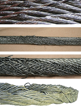
Example: Severe crown wire breaks on a 10-strand overhead crane wire rope. Crown breaks originate at the OUTSIDE of the rope at the contact point between rope and sheave/drum.
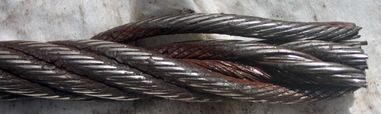
Remove the rope from service even if you find a SINGLE individual wire break which originates from inside of the rope. These so called VALLEY breaks have shown to be the cause for unexpected complete rope failures.
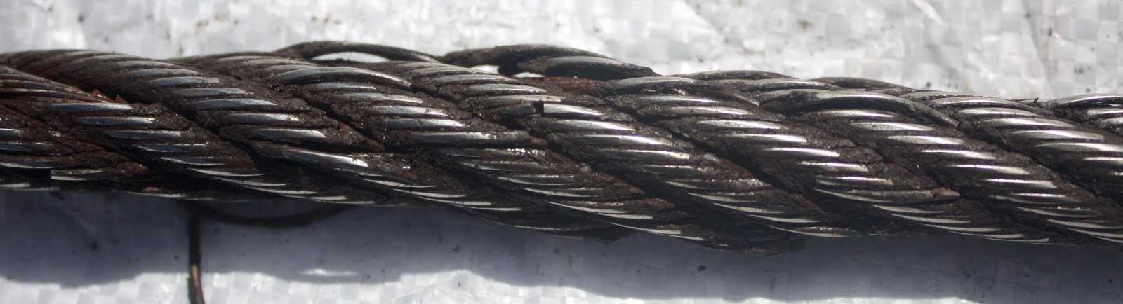
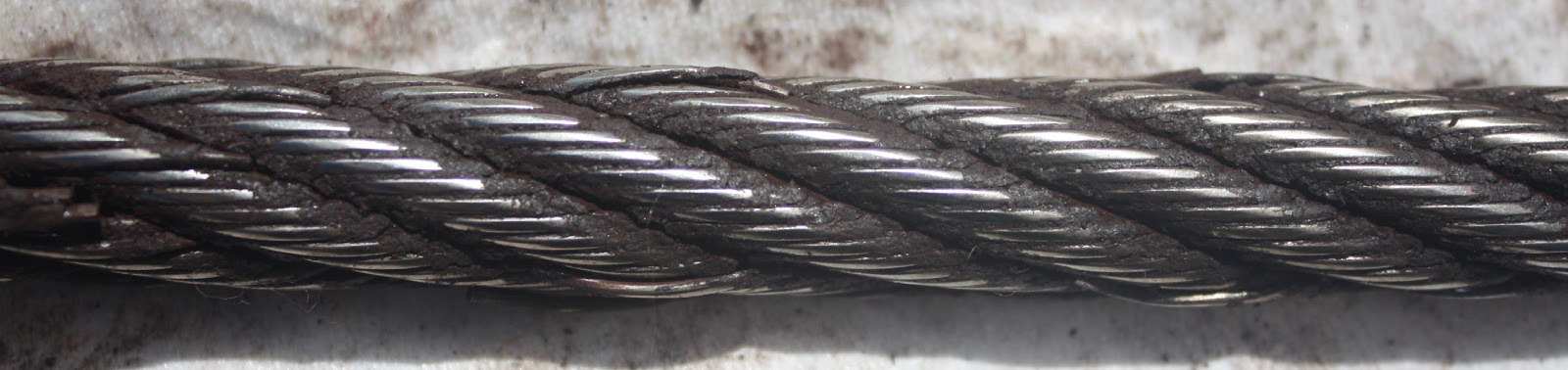
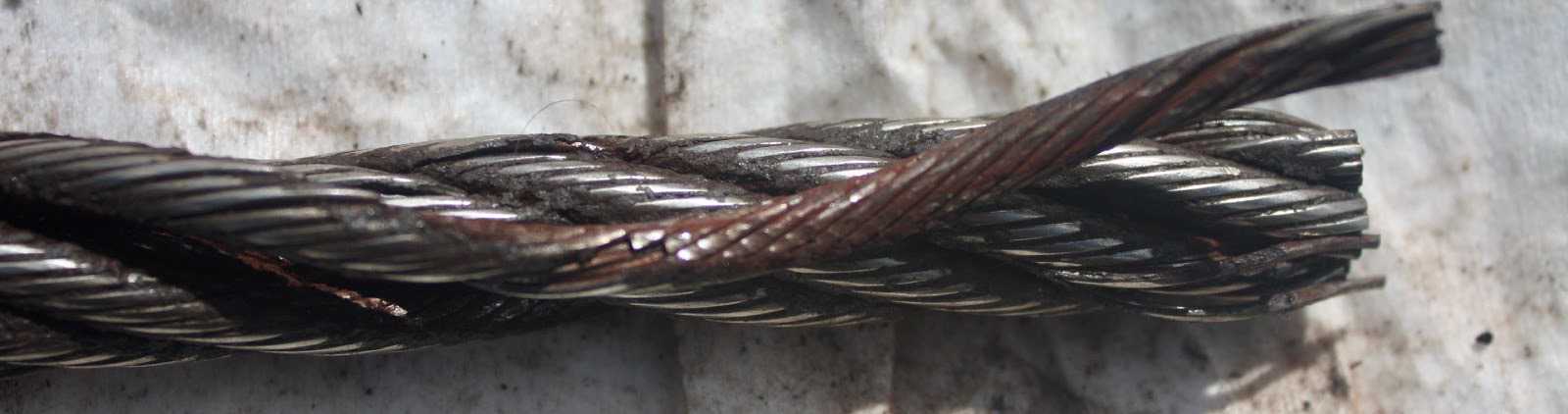
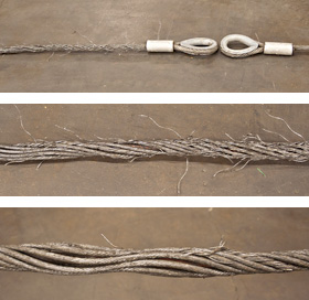
These 3 picture show what happens when you connect a left-lay rope to a right-lay rope, as done with this boom pendant extension. Both ropes are opening up to the point where the strands are nearly parallel to each other; they completely untwisted themselves and developed excessive wire breaks.
The result of such non-tensioning of the layers are looping of individual wires, completely crushed strands, total deterioration of a non-rotating rope due to gross neglect of inspection procedure.
NOTE: For a more indepth discussion on wire rope discard and inspection we suggest to attend our “Wire Rope” and “SlingMax® Rigger’s Mortis Seminar”. Call 1.800.457.9997 for details and dates.
Like all industrial equipment, aircraft cables and wire ropes wear while in service, and will require replacement. Though the cycle life of each cable varies based on construction and application, factors such as load and pulley condition can actually reduce this lifespan by triggering wire breaks. Not all wire breaks look the same, and understanding these differences can help detect issues in your system before they damage additional cables, or put human lives in danger. Here is a quick guide to help you understand where wire breaks occur (crowns vs. valleys), and three common examples of wire breaks (tension, fatigue, and abrasion).
Wire breaks typically occur in two different locations on the outside of wire rope or aircraft cable. The first location is on the crowns of the strands, which are the highest points with the most surface area exposure. The second location is the valleys, or the spaces between the strands. Though crown breaks typically result from normal wear and tear, valley breaks are more suspicious and may indicate issues with the pulley system or wire rope itself.
Wires that have been worn to a knife-edge thinness are characteristic of abrasion breaks. Abrasion can occur from a number of different sources, but sheaves are the most common. Remember to check sheaves for signs of wear, damage, or deformity and replace as necessary.
If you notice one end of a broken wire is cupped, and the other end resembles a cone, your wire rope likely experienced a tension break. Tension breaks result from excessive loading, causing the wires to stretch beyond their limits until they snap. Once one wire break appears, others will continue to occur if the cable is not addressed.
Fatigue damage is usually represented by zig-zag breaks with square ends. Like abrasion breaks, fatigue breaks can be triggered by a broad range of factors, including incorrect pulley size and excessive vibration. Check for worn pulleys and slack in the system to prevent issues from exacerbating.
Once you have replaced your damaged pulleys, or removed sharp obstructions in your system, begin your quote for brand new wire rope at https://strandcore.com/contact/. Our wire rope craftsmen can help you select the ideal wire rope for your application, and oftentimes provide a better solution for your existing setup. Browse our selection ofwire rope and aircraft cableonline, and do not hesitate to contact our sales team at sales@sanlo.com if you have any questions.
All wire ropes will wear out eventually and gradually lose work capability throughout their service life. That"s why periodic inspections are critical. Applicable industry standards such as ASME B30.2 for overhead and gantry cranes or federal regulations such as OSHA refer to specific inspection criteria for varied applications.
You should thoroughly inspect all wire ropes at regular intervals. The longer it has been in service or, the more severe the service, the more thoroughly and frequently it should be inspected. Be sure to maintain records of each inspection.
Inspections should be carried out by a person who has learned through specialized training or practical experience of what to look for and who knows how to judge the importance of any abnormal conditions they may discover. It is the inspector"s responsibility to obtain and follow the proper inspection criteria for each application inspected.
Figure 1is what happens when a wire breaks under tensile load exceeding its strength. It"s typically recognized by the "cup and cone" appearance at the point of failure. The necking down of the wire at the point of failure to form the cup and cone indicates failure has occurred while the wire retained its ductility (the ability to change form without breaking).
Figure 2is a wire with a clear fatigue break. It is identified by the square end perpendicular to the wire. This break was produced by a torsion machine that"s used to measure the ductility. This break is similar to wire failures in the field caused by fatigue.
Figure 3 is a wire rope that has been subjected to repeated bending over sheaves under typical loads. This fatigue results in breaks in individual wires - these breaks are square and usually in the crown of the strands.
Figure 4 is an example of fatigue failure of a wire rope subjected to heavy loads over small sheaves. The breaks in the valleys of the strands are caused by "strand nicking." There may be crown breaks, too.
Figure 5 is a single strand removed from a wire rope subjected to "strand nicking." This condition is a result of adjacent strands rubbing against one another. While this is normal in a rope"s operation, the nicking can be accentuated by high loads, small sheaves or loss of core support. The ultimate result will be individual wire breaks in the valleys of the strands.
(3) Operational aids. Operations must not begin unless operational aids are in proper working order, except where the owner or lessee meets the specified temporary alternative measures. See WAC 296-155-53412 for the list of operational aids.Note:All accredited crane certifiers must meet and follow the requirements relating to fall protection, located in chapter 296-880 WAC, Unified safety standards for fall protection.
(a) Wire ropes must meet the crane or wire rope manufacturer"s specifications for size, type and inspection requirements. In the absence of the manufacturer"s specifications, follow the requirements for removal criteria located in this section, including Table 1.
Derricks63Consult rope mfg.Consult rope mfg.32*Also remove if you detect 1 wire broken at the contact point with the core or adjacent strand; so called valley breaks or evidence from any heat damage from any cause.Note:xd means times the "diameter."
(b) The accredited crane certifier must perform a complete and thorough inspection covering the surface of the working range plus 3 additional wraps on the drum of the wire ropes.
(ii) If the deficiency is localized, the problem is corrected by severing the wire rope; the undamaged portion may continue to be used. Joining lengths of wire rope by splicing is prohibited.
(e) Replacement rope must be of a compatible size and have a strength rating at least as great as the original rope furnished or recommended by the crane manufacturer.
(a) Sheave grooves must be free from surface defects that could damage the rope. The cross-sectional radius at the bottom of the groove should be such as to form a close fitting saddle for the size of rope used. The sides of the groove must be tapered outward and rounded at the rim to facilitate entrance of the rope into the groove. Flange rims must run true about the axis of rotation.
(a) A safe test area must be selected and all traffic and unauthorized personnel and equipment must be cleared from test area. This test area must be roped off or otherwise secured to prevent entry of unauthorized personnel and equipment;
Abrasion damage may occur when the rope contacts an abrasive medium or simply when it passes over the drum and sheaves. Therefore it is vital that all components be in proper working order and of the appropriate diameter for the rope. A badly corrugated or worn sheave or drum will seriously damage a new rope, resulting in premature rope replacement.
Corrosion is very difficult to evaluate but is a more serious cause of degradation than abrasion. Usually signifying a lack of lubrication, corrosion will often occur internally before there is any visible external evidence on the rope’s surface. A slight discoloration caused by rusting usually indicates a need for lubrication which should be tended to immediately. If this condition persists, it will lead to severe corrosion which promotes premature fatigue failures in the wires and strands, necessitating the rope’s immediate removal from service.
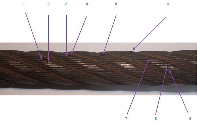
The table below shows the number of allowable wire breaks per crane type. The inspector must know the ASME standard for the equipment being inspected. The number of broken wires on the outside of the wire rope is an indication of its general condition and whether or not it must be considered for replacement. The inspector may use a type of spike to gently probe the strands for any wire breaks that do not protrude. Check as the rope runs at a slow speed over the sheaves, where crown (surface) wire breaks may be easier to see. Also examine the rope near the end connections. Keeping a detailed inspection record of the wire breaks and other types of damage will help the inspector determine the elapsed time between breaks. Note the area of the breaks and carefully inspect these areas in the future. Replace the rope when the wire breaks reach the total number allowable by ASME or other applicable specifications.
Valley breaks, or breaks in between strands, must be taken very seriously at all times!When two or more valley breaks are found in one lay-length, immediately replace the rope. Valley breaks are difficult to see; however, if you see one you can be assured that there are a few more hidden in the same area. Crown breaks are signs of normal deterioration, but valley breaks indicate an abnormal condition such as fatigue or breakage of other wires such as those in the core.
Once crown and valley breaks appear, their number will steadily and quickly increase as time goes on. The broken wires should be removed as soon as possible by bending the broken ends back and forth with a pair of pliers. In this way the wire is more likely to break inside the rope where the ends will be tucked away. If the broken wires are not removed they may cause further damage. The inspector must obey the broken wire standard; pushing the rope for more life will create a dangerous situation.
It is important to check and record a new rope’s actual diameter when under normal load conditions. During the life of the rope the inspector should periodically measure the actual diameter of the rope at the same location under equivalent loading conditions. If followed carefully, this procedure reveals a common rope characteristic—after an initial reduction, the overall diameter will stabilize and slowly decrease in diameter during the course of the rope’s life. This condition is normal. However, if diameter reduction is isolated to one area or happens quickly, the inspector must immediately determine (and correct, if necessary) the cause of the diameter loss, and schedule the rope for replacement.
Crushing or flattening of the strands can be caused by a number of different factors. These problems usually occur on multilayer spooling conditions but can occur by simply using the wrong wire rope construction. Most premature crushing and/or flattening conditions occur because of improper installation of the wire rope. In many cases failure to obtain a very tight first layer (the foundation) will cause loose or “gappy” conditions in the wire rope which will cause rapid deterioration. Failure to properly break-in the new rope, or worse, to have no break-in procedure at all, will cause similar poor spooling conditions. Therefore, it is imperative that the inspector knows how to inspect the wire rope as well as how that rope was installed.
Shock loading (bird-caging) of the rope is another reason for replacement of the rope. Shock loading is caused by the sudden release of tension on the wire rope and its resultant rebound from being overloaded. The damage that occurs can never be corrected and the rope must be replaced.
High stranding may occur for a number of reasons such as failure to properly seize the rope prior to installation or maintain seizing during wedge socket installation. Sometimes wavy rope occurs due to kinks or a very tight grooving problem. Another possibility is simply introducing torque or twist into a new rope during poor installation procedures. This condition requires the inspector to evaluate the continued use of the rope or increase the frequency of inspection.

Plastic-infused rope was developed to provide better fatigue, abrasion and crushing resistance derived from the cushioning and dampening effect of the plastic. However great the benefits, the plastic becomes at the very least, an inconvenience when trying to inspect the wire rope. Because of the plastic coating, some operators choose to forego inspection and run the ropes to failure. Other operators may just visually inspect the plastic coating. Both practices are wrong and carry equally the potential for disaster.
AbrasionandCrushing.In inspecting plastic-infused ropes, the basic inspection guidelines still apply and should be followed. Abrasion and crushing damage still may occur, so it is imperative to inspect flanges, sheaves, bearings, rollers and fairleads. Look for unusual wear patterns in the plastic—a key indicator that damage to the wire rope is occurring.
WireBreaks.Wire breaks still will occur in a plastic-infused rope, but are sometimes extremely difficult to detect, though occasionally a broken wire will protrude through the plastic. Every effort must be made to determine the overall condition of the rope. The plastic covering the crown (surface) wires is generally applied in a thin coat and tends to wear quickly in areas which pass over sheaves and drums. As the rope runs at a slow speed, inspect the rope in these areas. As the rope and plastic open up, the inspector will be afforded a look at not only the surface area but also the interstrand contact points. If a valley break is detected, immediately pull the rope from service. Also inspect areas where the plastic has peeled, regardless of the location of the “window.” Remove as much plastic from these areas as possible to allow for efficient and effective inspection techniques. Remember, due to the nature of plastic-infused ropes, there is no way to clearly determine the number of valley breaks.
Corrosion.Plastic-infused ropes provide only improved corrosion resistance. Regardless of manufacturers’ claims, a plastic-infused rope can corrode, and rope failure due to corrosion is still possible. Moisture is sometimes trapped in the rope and, as with all machines the lubricant may become ineffective over time. The inspector must visually check for any signs of corrosion damage as evidenced by rope bleeding or rouging. In addition, the diameter must be measured frequently. If there is any damage to the core, it will be detected by a reduction in diameter. Also inspect the lay of the rope. As the plastic is thinner over the crown wires, a thorough inspector may be able to determine a lengthening of lay, also a sign of rope deterioration. Especially when trying to determine lengthening of lay, watch for and inspect areas where the plastic pulls away from the rope. While peeling in and of itself is not an indication of rope deterioration and is a factor of normal wear, peeling in areas where no abrasion exists may signify a problem.
Maintenance Records.Equally important in inspecting plastic-infused ropes is maintaining accurate service records. The service records of previous ropes will provide a guideline as to the expected life of the rope. However, they should not be used alone or only in conjunction with visual inspections due to the number of variables which exist, including installation, spooling and manufacturing practices. Maintenance records must be used in combination with both visual and physical inspection techniques to be truly of value in determining the remaining life of the rope.
Die drawn and swaged ropes fall into the compacted category. Compacting serves several purposes. By flattening the outer wires, metallic area increases allowing for a higher breaking strength as well as improved crushing and abrasion resistance. In addition, the compaction minimizes interstrand nicking and thereby improves fatigue resistance.
In the inspection of compacted rope designs, again it is imperative to follow the basic inspection guidelines and use both visual and actual measuring techniques to determine the remaining life of the rope. In fact, actual measuring techniques are very important when inspecting these ropes. While corrosion is relatively easy to visually determine, diameter reduction may not be due to the compacted rope’s appearance. Therefore, the inspector must regularly measure for diameter reduction and closely examine the rope for lay lengthening. Measurements must be recorded and the rope monitored for sudden variations.
By and large the most difficult retirement criteria to determine in compacted ropes are wire breaks. These breaks may not protrude from the rope due to the compaction and can be overlooked easily. Because of this, the inspector must slowly and carefully examine the rope, especially in those areas passing over drums and sheaves or in areas where problems existed in previous ropes.
A wire break may appear as nothing more than a crack in the wire, and again can be overlooked easily. If the inspector notes a “flaw” in a wire, it should be checked carefully. The inspector should carry some type of magnifying device to determine if a flaw is actually a break. If a break has occurred, thoroughly check the area for additional breaks, both on the crown and in the valleys. Remember, valley breaks in round strand ropes are difficult to determine; compaction only increases the difficulty. The inspector must be slow and methodical in inspecting compacted ropes; a quick check will reveal nothing.
Overall, perhaps the most important inspection technique is recognizing the limits of wire rope. While it’s true that compacted and plastic-infused ropes are more durable, neglect and abuse still will quickly end the rope’s life. There is no substitute for proper installation, handling and inspection techniques in combination with a preventative maintenance program.
(a) Breaking Strength. All hoisting wire rope shall be of such breaking strength as to provide a minimum factor of safety of seven. The factor of safety (F) shall be calculated by the following formula:SN
A representative of the user of the material hoist shall be appointed and this representative shall keep written reports of the rope condition on file at the work site. The representative shall have the authority to order wire rope replacements and keep unsafe wire rope from being used.
Inspection periods shall be set-up for each material-hoist wire rope. The frequency of inspection shall be determined by consideration of environment, degree of hazard to materials, frequency of operation, and the frequency with which the rope is subjected to its capacity limits. Inspections shall be made not less often than once each 30 days.
The working length of the wire rope shall be unwound from the hoist drum. Thorough inspection shall be made of the rope sections that pass over sheaves, drums, or contact saddles, or which make opposing turns. The rope close to end attachments shall be carefully inspected.
Sheaves, guards, guides, drums, flanges, and other surfaces contacted by wire rope during operation should be examined at the time of inspection. Any condition harmful to the rope in use at the time should be corrected.
(2) Broken Wires. One or more valley breaks shall be cause for replacement. (A valley break is a wire break occurring in the valley between two adjacent strands.)
Six randomly distributed broken wires in one rope lay, or three broken wires in one strand in one rope lay, shall be cause for replacement. (A rope lay is the length along the rope in which one strand makes a complete revolution around the rope.)
(3) End Attachments. Development of broken wires in the vicinity of attachments shall be cause for replacement. If this condition is localized in an operating rope and the section in question can be eliminated by making a new attachment, this can be done rather than replacing the entire rope.
(4) Abrasion. Abrasion, scrubbing, flattening, or peening causing loss of more than one-third of the original diameter of the outside wires shall be cause for replacement.
(7) Reduction of Rope Diameter. Reduction from nominal diameter of more than 3/64-inch for diameters up to and including 3/4-inch; 1/16-inch for diameters 7/8 to 1 1/8 inches; and 3/22-inch for diameter 1 1/4 to 1 1/2 inches shall be causes for replacement. Marked reduction in diameter indicates deterioration of the core.
(d) Wire Rope Installation. Hoisting ropes shall be installed in accordance with the wire rope manufacturer"s recommendations. The hoisting ropes shall be secured to the drum by clamps or by an approved equivalent means.
(1) Pitch diameters of drums shall be a minimum of 24 times the nominal rope diameter. The drum flange shall extend at least 2 inches radially beyond the last layer of rope when all rope is coiled on the drum.
(3) All hoisting wire rope shall be improved plow steel grade or stronger, and equal in flexibility to 6 x 19 classification wire rope. The joining of hoisting ropes by splicing is prohibited.
(4) There shall be at least 4 feet of clearance between the cathead sheave and the hoisting-rope fastening on the platform, cage, or bucket when either is at the uppermost terminal or landing.
(7) Load-bearing sheaves for wire rope shall be grooved to accommodate the rope and shall have a diameter at least 20 times that of the wire rope. For minimum tread diameter of sheaves see Table 2. (The diameter of a sheave is measured at the bottom of the grooves.)
(9) Defective and worn sheaves that may cause equipment failure or damage to the wire rope shall be replaced. If pillow blocks are used, they shall be mounted on top of beams and securely bolted. Open bearings shall not be used.
Hoist cars shall be suspended by steel wire ropes attached to the car frame or passing around sheaves attached to the car frame specified in Section 1604.16.
(1) Only steel wire ropes having the commercial classification "elevator wire rope," or specifications recommended by wire rope manufacturers for hoist use, shall be used for the suspension of hoist cars or for the suspension of counterweights.
A new tag shall be installed at each rope renewal. The material and marking of the rope data tag shall conform to the requirements of Section 1604.21(d), except that the height of the letters and figures shall be not less than 1/16-inch.
The factors of safety of the suspension wire ropes shall be not less than shown in Table 5. Figure 5 gives the minimum factors of safety for intermediate rope speeds. The factor of safety shall be based on the actual rope speed corresponding to the rated speed of the car. The factor of safety shall be calculated by the following formula:S x N
NOTE: In the case of multiple roping, the number of runs of rope (N) under the load will be: twice the number of ropes used, for 2:1 roping; three times the number of ropes used, for 3:1 roping, etc.Table 5
Car suspension ropes of winding-drum machines shall have the ends of the rope secured to the drum or drum flange by means of clamps or tapered sockets or by other means approved by the enforcing authorities.
Wire suspension ropes of drum type machines shall have not less than three wraps of the rope on the drum when the car is resting on the fully compressed buffers.
Hoisting and counterweight wire ropes shall be attached to cars and counterweights by means of zinc-coated or galvanized drop forged fist grips or equal and wire rope thimbles, or by approved special fastening devices. When fist grips are used, the minimum number, spacing, and tightening torque shall be in accordance with the instructions of the grip manufacturer. Grips shall be periodically checked and retightened to the recommended torque.
When extra wire rope is carried on top of the frame of the hoisting platform, a drum and clamp tie down or equivalent type anchor device, which will not damage or deform the wire rope, shall be used.
Babbitted rope sockets shall be prohibited except on permanent passenger or freight elevators which are temporarily being used as construction personnel hoists.
(1) A representative of the user of the personnel hoist shall be appointed, and this representative shall keep written records of the rope condition on file at the work site.
(4) Examination of traction machine ropes and counterweight ropes of drum type hoists should preferably start with the car located at the top of the hoistway and should be made from the top of the car, with the ropes examined on the counterweight side.
(6) Where a traction or drum machine is located below, the portions of the ropes leading from the driving machine drum or sheave and from the counterweight to the overhead sheaves can be examined from the top of the car as it descends, except for a small portion which must be examined from the pit.
(7) The rope should be marked with chalk to indicate location of unexamined sections which must be inspected from other locations such as the pit or overhead machinery space.
(8) Sheaves, guards, guides, drums, flanges, and other surfaces contacted by wire rope during operation should be examined at the time of inspection. Any condition harmful to the rope shall be corrected.
If one wire rope of a set requires replacement, the entire set of ropes shall be replaced. Wire rope shall be removed or replaced immediately if it has one or more of the following defects:
(3) Six randomly distributed broken wires in one rope lay or three broken wires in one strand in one rope lay. (A rope lay is the length along the rope in which one strand makes a complete revolution around the rope.)
(4) Development of broken wires in the vicinity of attachments. If this condition is localized in an operating rope and the section in question can be eliminated by making a new attachment, this may be done rather than replacing the entire rope.
Governor ropes shall be replaced on the same basis as hoisting ropes. (These ropes are lightly loaded and may show little or no wear. Inspectors should check for fatigued wires in strand valleys by bending over a small radius.)

Wire Rope is an item often found on Wire Rope Cranes. Unfortunately, though these wires are not unbreakable and can/will succumb to the pressure of constant use and may potentially snap when in use. Which is why it is important to know what to look out for in an unsafe wire rope, the Government of Canada recommends a visual inspection of the wire before each use, but full inspections should be undertaken by a trained professional periodically. This article will cover what causes wire ropes to break, what your professional inspector will do to ensure your rope is safe and what you can look out for when completing your frequent inspection to ensure the rope is safe to work with.
When you hear the term wire rope you may picture in your mind a metal and seemingly unbreakable rope, and through wire ropes, can and will stand up better than many other rope types it is unfortunately not unbreakable. Some things that can cause a wire rope to break include:
Kinks caused by improper installation of a rope, sudden release of a load or knots that were made to shorten a rope can cause the rope to become compromised
Many of these causes can be minimized by the use of proper crane design and rope maintenance procedures, most of these causes though are unavoidable and are considered to be part of a normal rope life. The two main causes that are considered unavoidable are crushing and internal and external fatigue.
Many wire ropes are subject to a lot of repetitive bending over a sheave, which causes the wire to develop cracks in its individual wires. These broken wires often develop in the sections that move over sheaves. This process will become escalated if a rope travels on and off of a grooved single layer drum, which causes this to go through a bending cycle. Tests in the past have shown that winding on a single layer drum is equal to bending over a sheave because it causes similar damage.
Fatigue breaks often develop in segments as stated before these segments are usually the part of the rope surface that comes into direct contact with a sheave or drum. Because this is caused by external elements rubbing, oftentimes these breakages are external and visible for the eye to see. Once broken wires start to appear, it creates a domino effect and quickly much more will appear. Square ends of wires are common for fatigue breaks. These breaks are considered a long-term condition and are to be considered part of the normal to the operating process.
Internal Breaks,these breaks can develop over time-based upon the loading of the hoist. Many ropes are made of a torque-balanced multi-strand design, which comprises of two or more layers of strands. A torque balance is created in multi-strand ropes, by layering the outside and inside ropes in opposite directions. Multi-strand ropes offer much more flexibility and have a more wear-resistant profile. Though the wires in these ropes touch locally and at an angle, which causes them to be subject to both the effect of radial load, relative motion between wires and bending stresses when bent on sheaves or drums.
Nicking and fatigue patterns such as the ones discussed before occur in Independent Wire Rope Cores or IWRC ropes. IWRC ropes have outer wires of the outer strands, which have a larger diameter than the outer core strands. This helps to minimize inner strand nicking between the outer strands of the IWRC. The outer strands and the IWRC strands are approximately parallel. Often their neighbouring strands support these outer strands while the outer IWRC wires are relatively unsupported.
With these geometrical features it allows for the wire to fluctuate under tensile loads, the outer IWRC wires are continuously forced into valleys in between the outer strand wires and then released. This system results in secondary bending stresses which leads to a large number of core wires with fatigue breaks. These breaks are often close together and form in groups. This eventually leads to the IWRC breaking or completely disintegrating into short pieces of wire that lay, half a length long. This condition is often called complete rope core failure.
It is as the IWRC fails, and the outer strands lose their radial support then valley breaksform. Valley breaks occur when the outer strand wires bear against each other tangentially. This results in interstrand nicking, which restricts the movement of strands within the rope; without the freedom to move, secondary fatigue breaks occur in the outer strands, which will develop a stand tangent points. These breaks occur in the valleys between the outer strands hence why they are called valley breaks.
So to go over what we just learned, internal broken wires occur often in ropes that are operated with large diameter sheaves and high factors of safety. These breakages can occur when a reeving system incorporates sheaves lined with plastic or all plastic sheaves; these sheave units offer more elastic support than their steel counterparts. Which causes the pressure between outer wires and sheave grooves to be reduced to the point where the first wire breaks will occur internally.
If a section of a rope travels on and off of a grooved multi-layer drum, then it goes through what is called a bending cycle. The bending cycle occurs by a section of rope spooling in the first layer and is bent around the smooth drum surface, but when the second layer rolls around the rope section in the first layer will be spooled over. This causes the first layer to become compressed and damaged on the upper side by the second rope layer. With continued spooling the rope layers in the second and higher layers will, in turn, be damaged on both sides during contact with their neighbouring rope layers. This damage is caused both by the compression of the rope and by the rope laying on a rough surface.
Accelerated wear occurs where the point of the rope is squeezed between the drum flange and the previous layer. Often times the slap of rope at the crossover points causes peening, martensitic embrittlement and/or wire plucking, further associated rope damage is caused when the rope crosses over from layer to layer on a drum.
Also, if the lower wire rope areas where not spooled under sufficiently high tension the lower wraps can become displaced by the additional rope sections which would allow for these new rope sections to slide down in between them, which will lead to severe rope damage.
Many regulators have decided that the Statutory Life Policy be overly wasteful and they tend to use the Retirement for Clause Policy. A wire rope deteriorates slowly over its entire service, but to be aware of the state of deterioration, a wire rope must be periodically inspected. Moderate deterioration is normally present, and low levels of deterioration do not justify retirement. Which is why you have wire rope inspections to monitor the normal process of deterioration. This ensures that the rope can be retired before it can become dangerous. Besides, these inspections can detect unexpected damage or corrosion on the wire rope which will allow you to take corrective actions to ensure the longevity of the wire rope.
This system is useful for detecting external rope deterioration. To use this approach, the inspector will lightly grab the rope with a rag. The inspector then glides the cloth over the rope. Often times external broken wires will porcupine (stick up). When the rope moves along the wire it will be snagged on the broken wire. The inspectorwill then stops dragging the cloth along the wire and visually inspects the condition of the wire.
Frequently broken wires often do no porcupine, which is why a different test procedure must be utilized. This test involves moving along the rope two or three feet at a time and visually examining the rope. This method though can become tiresome because oftentimes the rope is covered in grease and many internal and external defects will avoid detection through this method.
Another method involves measuring the wire ropes diameter. This involves comparing the diameter of the current rope to the original rope’s diameter. Changes in the diameter of the rope indicate external and/or internal rope damage. This method is not perfect because many different wire breakages damages do not change the diameter of the rope.
You can also check for several visible signs of distributed losses of the metallic cross-sectional area. This is often caused by corrosion, abrasion and wear. To internally check for damage, you can insert a marlinspike under two strands and rotate it to lift the strands and open the rope.
Visual inspections are often not well suited for the detection of internal rope damage. This means that they have limited value as the only means of wire rope inspection. Though visual inspections do not require special machines. When completed by a knowledgeable and experienced rope examiner through visual inspections can be valuable tools for evaluating rope degeneration.
Electromagnetic Inspections or EM gives a detailed insight into the exact condition of a rope. EM is a very reliable inspection method and is a universally accepted method for inspecting wire ropes for mining, ski lifts and other similar industries. There are two distinct EM inspection methods, which have been developed to classify defects called Localized-Flaw (LF Inspection) and Loss-of-Metallic-Area Inspection (LMA Inspection type)
LF Inspection is similar to the rag-and-visual method. This inspection method is suited primarily for finding localized flaws, such as broken wires. Which is why small hand-held LF instruments are called electronic rags.
Electromagnetic and visual wire rope inspection methods are like peanut butter and jelly or cookies and milk they are the perfect combination, and both are essential for safe rope operation. Which is why both methods are often used to ensure maximum safety.
A program that involves periodic inspections is extremely effective. To establish baseline data for future inspections, a wire rope inspection program should begin with an initial inspection after a break-in period. Then the inspections should follow at scheduled intervals, with documentation of the ropes deterioration over its entire service life.
For multi-strand ropes often times visual inspections are ineffective which is why statutory life policy for a ropes retirement is often adopted. This means that these ropes are often discarded long before they should be meaning millions of dollars’ worth of perfectly good wire ropes are being thrown away annually.
Some people have suggested that non-rotating ropes should not be used if cranes use a single layer winding on a drum. Following this line of thought, this would mean multi-strand ropes should be used only when winding on multi-layer drums. This would cause wires to break the surface faster than internal wire damage can occur, these non-rotating wire ropes will be replaced long before internal fatigue can set in.
When internal broken wires are the problem electromagnetic rope testing can be the solution. Though there are some factors one needs to take into account such as certain regulations require rope retirement when a certain number of broken wires per unit of rope length exceed a set limit. This discard number that is specified in retirement standards refers solely to external wire breaks. This means the condition of a wire rope with internal breaks is therefore left up to the inspector.
Though you also need to take into account detailed detection and quantitative characterization of internal broken wires in ropes with many breaks and cluster breaks could be a problem. These difficulties are caused by the fact that electromagnetic wire rope can be influenced by several parameters such as:
Clusters of broken wires can cause an additional problem because the relative position of broken wires concerning each other within the rope is not known
Broken wires with zero or tight gap widths are not detectable by electromagnetic inspection because they do not have a sufficient magnetic leakage flux.
When you consider all of this you can quickly realize that you can only estimate the number of broken wires that have formed on a wire rope. You can use the LF trace for the detection of broken wires, though unfortunately it is not quantitative so it cannot be used to estimate the number of broken wires. Though it is good to note that if any internal broken wires are present an LMA trace will show rapid relatively small variations of a cross-section.
An electromagnetic inspection will help to enhance the accuracy and reliability of the inspection, by combining visual and EM methods they will be able to detect deterioration at the earliest stages. The inspections can be then used as an effective preventive maintenance tool. For example, the inspector early on detects corrosion, and you immediately apply the corrective action of improving the lubrication of the wire rope.
Wire ropes should be inspected by a certified inspector when installing it, and periodically throughout its life cycle. A wire rope should go through a quick, but thorough inspection every day that you use it at the beginning and end of each shift and you should keep records of all inspections. Ensure that your certified wire rope inspector uses a combination of visual inspection methods and electromagnetic inspection methods because this will ensure the optimum safety and longevity of the rope. This is especially true for ropes that are more likely to develop internal broken wires, and inspections completed by a certified inspector is the best way of having a preventive maintenance program and extending the life of your wire rope.
Queensland Division of Workplace Health and Safety, “Non-rotating hoist wire ropes, multi fall configurations, Health and Safety Alert,” http://www.whs.qld.gov.au/alerts/97-i-5.pdf
Verreet, R. “Wire rope damage due to bending fatigue and drum crushing,” O.I.P.E.E.C.(International Organization for the Study of the Endurance of Wire Rope) Bulletin 85, June 2003, Reading (UK), ODN 0738, pp. 27-46.


 8613371530291