
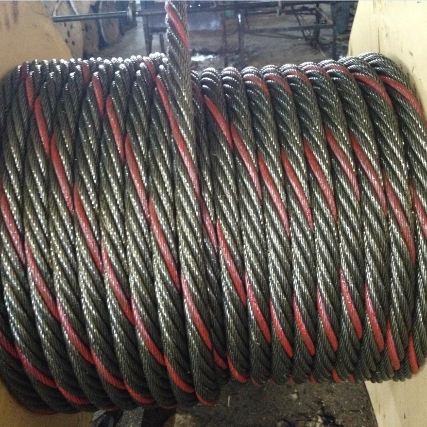
very strong wire rope free sample

Our samples of rope, cord, and shock cord are 1-2 ft in length. The intent of our sample request program is to provide a pre-purchase physical sample for those customers needing more information for them to make a sound purchasing decision.
To request a sample piece, please send an email to samples@qualitynylonrope.com with your name, address, and the item number(s) of the samples you want in order for your request to be fulfilled.

Wire rope and cable are each considered a “machine”. The configuration and method of manufacture combined with the proper selection of material when designed for a specific purpose enables a wire rope or cable to transmit forces, motion and energy in some predetermined manner and to some desired end.
Two or more wires concentrically laid around a center wire is called a strand. It may consist of one or more layers. Typically, the number of wires in a strand is 7, 19 or 37. A group of strands laid around a core would be called a cable or wire rope. In terms of product designation, 7 strands with 19 wires in each strand would be a 7×19 cable: 7 strands with 7 wires in each strand would be a 7×7 cable.
Materials Different applications for wire rope present varying demands for strength, abrasion and corrosion resistance. In order to meet these requirements, wire rope is produced in a number of different materials.
Stainless Steel This is used where corrosion is a prime factor and the cost increase warrants its use. The 18% chromium, 8% nickel alloy known as type 302 is the most common grade accepted due to both corrosion resistance and high strength. Other types frequently used in wire rope are 304, 305, 316 and 321, each having its specific advantage over the other. Type 305 is used where non-magnetic properties are required, however, there is a slight loss of strength.
Galvanized Carbon Steel This is used where strength is a prime factor and corrosion resistance is not great enough to require the use of stainless steel. The lower cost is usually a consideration in the selection of galvanized carbon steel. Wires used in these wire ropes are individually coated with a layer of zinc which offers a good measure of protection from corrosive elements.
Cable Construction The greater the number of wires in a strand or cable of a given diameter, the more flexibility it has. A 1×7 or a 1×19 strand, having 7 and 19 wires respectively, is used principally as a fixed member, as a straight linkage, or where flexing is minimal.
Selecting Wire Rope When selecting a wire rope to give the best service, there are four requirements which should be given consideration. A proper choice is made by correctly estimating the relative importance of these requirements and selecting a rope which has the qualities best suited to withstand the effects of continued use. The rope should possess:Strength sufficient to take care of the maximum load that may be applied, with a proper safety factor.
Strength Wire rope in service is subjected to several kinds of stresses. The stresses most frequently encountered are direct tension, stress due to acceleration, stress due to sudden or shock loads, stress due to bending, and stress resulting from several forces acting at one time. For the most part, these stresses can be converted into terms of simple tension, and a rope of approximately the correct strength can be chosen. As the strength of a wire rope is determined by its, size, grade and construction, these three factors should be considered.
Safety Factors The safety factor is the ratio of the strength of the rope to the working load. A wire rope with a strength of 10,000 pounds and a total working load of 2,000 pounds would be operating with a safety factor of five.
It is not possible to set safety factors for the various types of wire rope using equipment, as this factor can vary with conditions on individual units of equipment.
The proper safety factor depends not only on the loads applied, but also on the speed of operation, shock load applied, the type of fittings used for securing the rope ends, the acceleration and deceleration, the length of rope, the number, size and location of sheaves and drums, the factors causing abrasion and corrosion and the facilities for inspection.
Fatigue Fatigue failure of the wires in a wire rope is the result of the propagation of small cracks under repeated applications of bending loads. It occurs when ropes operate over comparatively small sheaves or drums. The repeated bending of the individual wires, as the rope bends when passing over the sheaves or drums, and the straightening of the individual wires, as the rope leaves the sheaves or drums, causing fatigue. The effect of fatigue on wires is illustrated by bending a wire repeatedly back and forth until it breaks.
The best means of preventing early fatigue of wire ropes is to use sheaves and drums of adequate size. To increase the resistance to fatigue, a rope of more flexible construction should be used, as increased flexibility is secured through the use of smaller wires.
Abrasive Wear The ability of a wire rope to withstand abrasion is determined by the size, the carbon and manganese content, the heat treatment of the outer wires and the construction of the rope. The larger outer wires of the less flexible constructions are better able to withstand abrasion than the finer outer wires of the more flexible ropes. The higher carbon and manganese content and the heat treatment used in producing wire for the stronger ropes, make the higher grade ropes better able to withstand abrasive wear than the lower grade ropes.
Effects of Bending All wire ropes, except stationary ropes used as guys or supports, are subjected to bending around sheaves or drums. The service obtained from wire ropes is, to a large extent, dependent upon the proper choice and location of the sheaves and drums about which it operates.
A wire rope may be considered a machine in which the individual elements (wires and strands) slide upon each other when the rope is bent. Therefore, as a prerequisite to the satisfactory operation of wire rope over sheaves and drums, the rope must be properly lubricated.
Loss of strength due to bending is caused by the inability of the individual strands and wires to adjust themselves to their changed position when the rope is bent. Tests made by the National Institute of Standards and Technology show that the rope strength decreases in a marked degree as the sheave diameter grows smaller with respect to the diameter of the rope. The loss of strength due to bending wire ropes over the sheaves found in common use will not exceed 6% and will usually be about 4%.
The bending of a wire rope is accompanied by readjustment in the positions of the strands and wires and results in actual bending of the wires. Repetitive flexing of the wires develops bending loads which, even though well within the elastic limit of the wires, set up points of stress concentration.
The fatigue effect of bending appears in the form of small cracks in the wires at these over-stressed foci. These cracks propagate under repeated stress cycles, until the remaining sound metal is inadequate to withstand the bending load. This results in broken wires showing no apparent contraction of cross section.
Experience has established the fact that from the service view-point, a very definite relationship exists between the size of the individual outer wires of a wire rope and the size of the sheave or drum about which it operates. Sheaves and drums smaller than 200 times the diameter of the outer wires will cause permanent set in a heavily loaded rope. Good practice requires the use of sheaves and drums with diameters 800 times the diameter of the outer wires in the rope for heavily loaded fast-moving ropes.
It is impossible to give a definite minimum size of sheave or drum about which a wire rope will operate with satisfactory results, because of the other factors affecting the useful life of the rope. If the loads are light or the speed slow, smaller sheaves and drums can be used without causing early fatigue of the wires than if the loads are heavy or the speed is fast. Reverse bends, where a rope is bent in one direction and then in the opposite direction, cause excessive fatigue and should be avoided whenever possible. When a reverse bend is necessary larger sheaves are required than would be the case if the rope were bent in one direction only.
Stretch of Wire Rope The stretch of a wire rope under load is the result of two components: the structural stretch and the elastic stretch. Structural stretch of wire rope is caused by the lengthening of the rope lay, compression of the core and adjustment of the wires and strands to the load placed upon the wire rope. The elastic stretch is caused by elongation of the wires.
The structural stretch varies with the size of core, the lengths of lays and the construction of the rope. This stretch also varies with the loads imposed and the amount of bending to which the rope is subjected. For estimating this stretch the value of one-half percent, or .005 times the length of the rope under load, gives an approximate figure. If loads are light, one-quarter percent or .0025 times the rope length may be used. With heavy loads, this stretch may approach one percent, or .01 times the rope length.
The elastic stretch of a wire rope is directly proportional to the load and the length of rope under load, and inversely proportional to the metallic area and modulus of elasticity. This applies only to loads that do not exceed the elastic limit of a wire rope. The elastic limit of stainless steel wire rope is approximately 60% of its breaking strength and for galvanized ropes it is approximately 50%.
Preformed Wire Ropes Preformed ropes differ from the standard, or non-preformed ropes, in that the individual wires in the strands and the strands in the rope are preformed, or pre-shaped to their proper shape before they are assembled in the finished rope.
This, in turn, results in preformed wire ropes having the following characteristics:They can be cut without the seizings necessary to retain the rope structure of non-preformed ropes.
They are substantially free from liveliness and twisting tendencies. This makes installation and handling easier, and lessens the likelihood of damage to the rope from kinking or fouling. Preforming permits the more general use of Lang lay and wire core constructions.
Removal of internal stresses increase resistance to fatigue from bending. This results in increased service where ability to withstand bending is the important requirement. It also permits the use of ropes with larger outer wires, when increased wear resistance is desired.
Outer wires will wear thinner before breaking, and broken wire ends will not protrude from the rope to injure worker’s hands, to nick and distort adjacent wires, or to wear sheaves and drums. Because of the fact that broken wire ends do not porcupine, they are not as noticeable as they are in non-preformed ropes. This necessitates the use of greater care when inspecting worn preformed ropes, to determine their true condition.

Wire rope is also known by many other names, such as: wire, multi-strand wire, flexible wire, cable, cord, steelcord, etc. but it is essentially a collection of small filaments wound around each other in a manner that largely retains its shape when bent, crushed and/or tensioned.
It is a system for significantly increasing the strength and flexibility of steel wire and is used in almost every important application we see around us. For example: suspension bridges, tyres, brake and accelerator cables (in cars), high-pressure flexible pipes, lifting and rigging cables, electrical conductors, etc. and it comes in many different forms. Fig 2 shows just a very small sample of available designs.
With minor variations, the generally accepted method for designating a wire rope construction in the industry is by describing it numerically. For example:
Whilst "IWRC" wire ropes offer a slightly greater tensile capacity (≈7%) than those with fabric or polymer fillers, the additional strength does not come from the tensile capacity of the core filaments but from improved dimensional stability under load. And whilst they are also much more resistant to crushing, they are stiffer than fibre core ropes and therefore not recommended for applications where tension occurs under bending.
Warrington (Fig 1) is a parallel lay construction with an outer layer comprising wires of alternating large and small diameters, each outer layer having twice the number of wires as the layer immediately beneath. The benefit of this design is to increase packing and therefore strength density, however, unless the different diameter filaments are of the same strength (unlikely), this construction is limited by the strength of the weakest filaments.
Seale (Figs 1 & 2 6x36) is also a parallel lay construction but with the same number of wires in each wire layer. All the wires in any layer are the same diameter. This is an alternative to the Warrington construction, with similar benefits and disadvantages.
Regular lay constructions are used much more widely (than Lang lay) because they have excellent structural stability and less tendency to unwrap under tension (see Rotating vs Non-Rotating below). However, because it has a knobbly (undulating) surface it will wear both itself and any surface over which it is run much more quickly than Lang lay wire rope.
Lang lay constructions have a flatter surface than regular lay constructions giving them better resistance to wear and bending fatigue, especially when made from flattened (elliptical) filaments. They are, however, much less structurally stable and subject to birdcaging if the wire rope is over-bent or twisted against its wrapped direction.
"Regular Lay", multi-strand constructions are normally subject to slightly less rotation under tension (than Lang lay) due to the opposite helical direction of the filaments (within the strands) and the strands (within the rope), however, you can improve their rotation characteristics still further by;
Whilst there are very distinct non-rotating constructions such as 19x7 and rotation-resistant designs such as 19x19, new ideas are evolving all the time and each manufacturer will have its own design preferences.
Fillers (Fig 2) may be fabric, polymer or even smaller diameter filaments (e.g. 6x36). Whilst they contribute little to the tensile strength of wire rope, they can significantly; improve performance under bending (fabric and polymer cores only), reduce axial growth, reduce rotation in rotation-resistant constructions, improve structural stability and increase fatigue life.
This filler material should not be included in strength (tensile capacity) calculations, but must be included in those for axial stiffness (extension). If it is ignored, your calculations will reveal excessive extension as the wire rope collapses.
Suspension bridges tend to be constructed from densely packed, single strand plain "Wire Rope" constructions using large diameter galvanised filaments. Little heed is paid to rotational resistance as strength is paramount and once tensioned, they should remain in that loading condition for their design life.
Lifting & winching normally require wire ropes of good flexibility and fatigue resistance. Therefore they tend to be similar to 6x36 but with fibre core instead of the IWRC in Fig 2
Remote operating cables such as hand-brakes and accelerators on cars normally only work in tension so they need to be strong but not necessarily stiff (as they are fully contained in reinforced outer sheaths). These tend to be manufactured from large diameter "TyreCord" or small diameter single-strand "Wire Rope".
Wire rope does not obey Hooke"s law. Therefore, you cannot accurately predict how much it will stretch for any specified force. This unpredictability applies to any section removed from the same manufactured length of cord and even between cords produced to the same specification but by different manufacturers.
CalQlata has decided that the accuracy of axial stiffness (EA) of wire rope falls outside its own levels of acceptability and therefore does not include it in the wire rope calculator. The extension calculated in the Wire Rope calculator (δLᵀ) is based upon the effect of axial tension on packing density. It is therefore important that core material is not ignored when using the calculator to evaluate this characteristic.
Wire rope does not obey Hooke"s law. Therefore, you cannot accurately predict how much it will twist for any specified torque. This unpredictability applies to any section removed from the same manufactured length of cord and even between cords produced to the same specification but by different manufacturers.
CalQlata has decided that the accuracy of torsional stiffness (GJ) of wire rope falls outside its own levels of acceptability and therefore does not include it in the wire rope calculator.
1) No wire rope calculator, whether dedicated or generic, will accurately predict the properties of any single construction under a wide range of loading conditions
2) No wire rope calculator, whether dedicated or generic, will accurately predict any single property for a range of constructions under a wide range of loading conditions
The only wire rope that can be reliably analysed is that which is used for suspension bridges, because; it comprises a single strand, is very densely packed, has negligible twist, contains filaments of only one diameter, is never subjected to minimum bending and every filament is individually tensioned.
There is a very good reason why manufacturers do not present calculated performance data for construction or design proposals, because even they cannot accurately predict such properties and quite rightly rely on, and publish, test data.
During his time working in the industry, the wire rope calculator"s creator has seen, created and abandoned numerous mathematical models both simple and complex. He has gradually developed his own simplified calculation principle based upon his own experience that still provides him with consistently reliable results of reasonable accuracy.
The purpose of CalQlata"s wire rope calculator is to provide its user with the ability to obtain a reasonable approximation for a generic construction, after which, accurate test data should be sought from the manufacturer for the user"s preferred construction.
The calculation principle in the wire rope calculator is based upon changes in the properties of the wire rope that occur with variations in packing density under tension
Bearing in mind the above limitations CalQlata can provide the following assistance when generating (manipulating) the wire rope calculator"s input data and interpreting its output
Alternatively, for wire rope with multiple filament diameters, you need to find an equivalent diameter with the following proviso; you must enter the minimum filament yield stress (SMYS)
It is expected that apart from fillers, all the material in the wire rope will be identical and therefore have the same density, i.e. using different materials will result in less than "best" performance. However, if such a construction is proposed, you can calculate an equivalent density as follows:
It is expected that apart from fillers, all the material in the wire rope will be identical and therefore have the same tensile modulus, i.e. using different materials will result in less than "best" performance. However, if such a construction is proposed, you should enter the highest tensile modulus.
The wire rope calculator simply adds together the total area of all the filaments and multiplies them by the SMYS entered, which represents a theoretical maximum breaking load that would exist if this load is equally shared across all of the filaments and the lay angles have been arranged to eliminate localised (point) loads between adjacent filaments.
If the wire rope has been properly constructed it is likely that its actual break load will be greater than 80% of this theoretical value. However, given the vagaries of wire rope construction, the actual break load can vary considerably dependent upon a number of factors. CalQlata suggest that the following factors may be used to define the anticipated break load of any given construction:
The axial stiffness and strain under load will be affected by this value, hence the reason why the most reliable (predictable) constructions tend to be minimum [number of] strands and single filament diameter. The Warrington and Seale constructions and combinations thereof tend to provide the highest packing density (but lowest flexibility) and there is little to be gained from using these constructions in more than single stranded wire rope as the benefit of high-packing density will be lost with no gain in flexibility.
The anticipated second moment of area of the wire rope at tension "T" due to deformation but insignificant flattening as it is assumed the wire rope will be bent over a formed (shaped) sheave or roller.
The anticipated tensile modulus of the wire rope at tension "T" due to deformation but insignificant flattening as it is assumed the wire rope will be bent over a formed (shaped) sheave or roller.
It is not advisable to induce this bend radius in operation due to uncertainties associated with wire rope construction, especially for dynamic applications. CalQlata suggests that a similar approach to that used for the break load (Fb) above also be applied here, i.e.:
A change in diameter will occur in all wire rope, irrespective of construction, until packing density has reached a limiting value. The value provided in the wire rope calculator is that which would be expected if the construction remains intact at the applied tension "T"
Unreliability of this value increases with complexity in wire rope due to its longitudinal variability and the increased likelihood of premature failure.
The accuracy of this data will range from about ±1% for wire rope with a single strand and a single filament diameter, up to about ±15% for constructions of similar complexity to OTR cord
A change in length of any wire rope will occur due to the fact that the packing density increases with tension. This is not, however, a linear relationship.
This can be an unreliable value as illustrated by tests carried out (by the author) on two pieces of wire rope supplied by the same well-known manufacturer both of which were cut from the same length, varied in tensile capacity by only 1.5%, but the tensile modulus (and strain at break) varied by 34%. Whilst this was an extreme case, significant variations have been seen in wire rope manufactured by a number of manufacturers.
Whilst the wire rope calculator does not calculate axial stiffness (see Calculation Limitations 9) above), CalQlata can suggest the following rule-of-thumb that will provide reasonable results for most constructions at the applied tension "T":
Whilst the wire rope calculator does not calculate bending stiffness (see Calculation Limitations 8) above), CalQlata can suggest the following rule-of-thumb that will provide reasonable results for most constructions at the applied tension "T":
Low complexity means single strand and single wire diameter. Medium complexity means multi-strand and single wire diameter. High complexity means multi-strand and multiple wire diameters.

Wire ropes are essential for safety purposes on construction sites and industrial workplaces. They are used to secure and transport extremely heavy pieces of equipment – so they must be strong enough to withstand substantial loads. This is why the wire rope safety factor is crucial.
You may have heard that it is always recommended to use wire ropes or slings with a higher breaking strength than the actual load. For instance, say that you need to move 50,000 lbs. with an overhead crane. You should generally use equipment with a working load limit that is rated for weight at least five times higher – or 250,000 lbs. in this case.
This recommendation is all thanks to the wire rope safety factor. This calculation is designed to help you determine important numbers, such as the minimum breaking strength and the working load limit of a wire rope.
The safety factor is a measurement of how strong of a force a wire rope can withstand before it breaks. It is commonly stated as a ratio, such as 5:1. This means that the wire rope can hold five times their Safe Work Load (SWL) before it will break.
So, if a 5:1 wire rope’s SWL is 10,000 lbs., the safety factor is 50,000 lbs. However, you would never want to place a load near 50,000 lbs. for wire rope safety reasons.
The safety factor rating of a wire rope is the calculation of the Minimum Break Strength (MBS) or the Minimum Breaking Load (MBL) compared to the highest absolute maximum load limit. It is crucial to use a wire rope with a high ratio to account for factors that could influence the weight of the load.
The Safe Working Load (SWL) is a measurement that is required by law to be clearly marked on all lifting devices – including hoists, lifting machines, and tackles. However, this is not visibly listed on wire ropes, so it is important to understand what this term means and how to calculate it.
The safe working load will change depending on the diameter of the wire rope and its weight per foot. Of course, the smaller the wire rope is, the lower its SWL will be. The SWL also changes depending on the safety factor ratio.
The margin of safety for wire ropes accounts for any unexpected extra loads to ensure the utmost safety for everyone involved. Every year there aredue to overhead crane accidents. Many of these deaths occur when a heavy load is dropped because the weight load limit was not properly calculated and the wire rope broke or slipped.
The margin of safety is a hazard control calculation that essentially accounts for worst-case scenarios. For instance, what if a strong gust of wind were to blow while a crane was lifting a load? Or what if the brakes slipped and the load dropped several feet unexpectedly? This is certainly a wire rope safety factor that must be considered.
Themargin of safety(also referred to as the factor of safety) measures the ultimate load or stress divided by theallowablestress. This helps to account for the applied tensile forces and stress thatcouldbe applied to the rope, causing it to inch closer to the breaking strength limit.
A proof test must be conducted on a wire rope or any other piece of rigging equipment before it is used for the first time.that a sample of a wire rope must be tested to ensure that it can safely hold one-fifth of the breaking load limit. The proof test ensures that the wire rope is not defective and can withstand the minimum weight load limit.
First, the wire rope and other lifting accessories (such as hooks or slings) are set up as needed for the particular task. Then weight or force is slowly added until it reaches the maximum allowable working load limit.
Some wire rope distributors will conduct proof loading tests before you purchase them. Be sure to investigate the criteria of these tests before purchasing, as some testing factors may need to be changed depending on your requirements.
When purchasing wire ropes for overhead lifting or other heavy-duty applications, understanding the safety dynamics and limits is critical. These terms can get confusing, but all of thesefactors serve an important purpose.
Our company has served as a wire rope distributor and industrial hardware supplier for many years. We know all there is to know about safety factors. We will help you find the exact wire ropes that will meet your requirements, no matter what project you have in mind.
Wire rope forms an important part of many machines and structures. It is comprised of continuous wire strands wound around a central core. There are many kinds of wire rope designed for different applications. Most of them are steel wires made into strands wound with each other. The core can be made of steel, rope or even plastics.
Wire ropes (cables) are identified by several parameters including size, grade of steel used, whether or not it is preformed, by its lay, the number of strands and the number of wires in each strand.
A typical strand and wire designation is 6x19. This denotes a rope made up of six strands with 19 wires in each strand. Different strand sizes and arrangements allow for varying degrees of rope flexibility and resistance to crushing and abrasion. Small wires are better suited to being bent sharply over small sheaves (pulleys). Large outer wires are preferred when the cable will be rubbed or dragged through abrasives.
There are three types of cores. An independent wire rope core (IWRC) is normally a 6x7 wire rope with a 1x7 wire strand core resulting in a 7x7 wire rope. IWRCs have a higher tensile and bending breaking strength than a fiber core rope and a high resistance to crushing and deformation.
A wire strand core (WSC) rope has a single wire strand as its core instead of a multistrand wire rope core. WSC ropes are high strength and are mostly used as static or standing ropes.
Wire ropes also have fiber cores. Fiber core ropes were traditionally made with sisal rope, but may also use plastic materials. The fiber core ropes have less strength than steel core ropes. Fiber core ropes are quite flexible and are used in many overhead crane applications.
The lay of a wire rope is the direction that the wire strands and the strands in the cable twist. There are four common lays: right lay, left lay, regular lay and lang lay. In a right lay rope the strands twist to the right as it winds away from the observer. A left lay twists to the left. A regular lay rope has the wires in the strands twisted in the opposite direction from the strands of the cable. In a lang lay rope, the twist of the strands and the wires in the strands are both twisted the same way. Lang lay ropes are said to have better fatigue resistance due to the flatter exposure of the wires.
Wire ropes are made mostly from high carbon steel for strength, versatility, resilience and availability and for cost consideration. Wire ropes can be uncoated or galvanized. Several grades of steel are used and are described in Table 1.
Steel cable wire is stiff and springy. In nonpreformed rope construction, broken or cut wires will straighten and stick out of the rope as a burr, posing a safety hazard. A preformed cable is made of wires that are shaped so that they lie naturally in their position in the strand, preventing the wires from protruding and potentially causing injury. Preformed wire ropes also have better fatigue resistance than nonpreformed ropes and are ideal for working over small sheaves and around sharp angles.
Lubricating wire ropes is a difficult proposition, regardless of the construction and composition. Ropes with fiber cores are somewhat easier to lubricate than those made exclusively from steel materials. For this reason, it is important to carefully consider the issue of field relubrication when selecting rope for an application.
There are two types of wire rope lubricants, penetrating and coating. Penetrating lubricants contain a petroleum solvent that carries the lubricant into the core of the wire rope then evaporates, leaving behind a heavy lubricating film to protect and lubricate each strand (Figure 2). Coating lubricants penetrate slightly, sealing the outside of the cable from moisture and reducing wear and fretting corrosion from contact with external bodies.
Both types of wire rope lubricants are used. But because most wire ropes fail from the inside, it is important to make sure that the center core receives sufficient lubricant. A combination approach in which a penetrating lubricant is used to saturate the core, followed with a coating to seal and protect the outer surface, is recommended. Wire rope lubricants can be petrolatum, asphaltic, grease, petroleum oils or vegetable oil-based (Figure 3).
Petrolatum compounds, with the proper additives, provide excellent corrosion and water resistance. In addition, petrolatum compounds are translucent, allowing the technician to perform visible inspection. Petrolatum lubricants can drip off at higher temperatures but maintain their consistency well under cold temperature conditions.
Asphaltic compounds generally dry to a very dark hardened surface, which makes inspection difficult. They adhere well for extended long-term storage but will crack and become brittle in cold climates. Asphaltics are the coating type.
Various types of greases are used for wire rope lubrication. These are the coating types that penetrate partially but usually do not saturate the rope core. Common grease thickeners include sodium, lithium, lithium complex and aluminum complex soaps. Greases used for this application generally have a soft semifluid consistency. They coat and achieve partial penetration if applied with pressure lubricators.
Petroleum and vegetable oils penetrate best and are the easiest to apply because proper additive design of these penetrating types gives them excellent wear and corrosion resistance. The fluid property of oil type lubricants helps to wash the rope to remove abrasive external contaminants.
Wire ropes are lubricated during the manufacturing process. If the rope has a fiber core center, the fiber will be lubricated with a mineral oil or petrolatum type lubricant. The core will absorb the lubricant and function as a reservoir for prolonged lubrication while in service.
If the rope has a steel core, the lubricant (both oil and grease type) is pumped in a stream just ahead of the die that twists the wires into a strand. This allows complete coverage of all wires.
After the cable is put into service, relubrication is required due to loss of the original lubricant from loading, bending and stretching of the cable. The fiber core cables dry out over time due to heat from evaporation, and often absorb moisture. Field relubrication is necessary to minimize corrosion, protect and preserve the rope core and wires, and thus extend the service life of the wire rope.
If a cable is dirty or has accumulated layers of hardened lubricant or other contaminants, it must be cleaned with a wire brush and petroleum solvent, compressed air or steam cleaner before relubrication. The wire rope must then be dried and lubricated immediately to prevent rusting. Field lubricants can be applied by spray, brush, dip, drip or pressure boot. Lubricants are best applied at a drum or sheave where the rope strands have a tendency to separate slightly due to bending to facilitate maximum penetration to the core. If a pressure boot application is used, the lubricant is applied to the rope under slight tension in a straight condition. Excessive lubricant application should be avoided to prevent safety hazards.
Some key performance attributes to look for in a wire rope lubricant are wear resistance and corrosion prevention. Some useful performance benchmarks include high four-ball EP test values, such as a weld point (ASTM D2783) of above 350 kg and a load wear index of above 50. For corrosion protection, look for wire rope lubricants with salt spray (ASTM B117) resistance values above 60 hours and humidity cabinet (ASTM D1748) values of more than 60 days. Most manufacturers provide this type of data on product data sheets.
Cable life cycle and performance are influenced by several factors, including type of operation, care and environment. Cables can be damaged by worn sheaves, improper winding and splicing practices, and improper storage. High stress loading, shock loading, jerking heavy loads or rapid acceleration or deceleration (speed of the cable stopping and starting) will accelerate the wear rate.
Corrosion can cause shortened rope life due to metal loss, pitting and stress risers from pitting. If a machine is to be shut down for an extended period, the cables should be removed, cleaned, lubricated and properly stored. In service, corrosion and oxidation are caused by fumes, acids, salt brines, sulfur, gases, salt air, humidity and are accelerated by elevated temperatures. Proper and adequate lubricant application in the field can reduce corrosive attack of the cable.
Abrasive wear occurs on the inside and outside of wire ropes. Individual strands inside the rope move and rub against one another during normal operation, creating internal two-body abrasive wear. The outside of the cable accumulates dirt and contaminants from sheaves and drums. This causes three-body abrasive wear, which erodes the outer wires and strands. Abrasive wear usually reduces rope diameter and can result in core failure and internal wire breakage. Penetrating wire rope lubricants reduce abrasive wear inside the rope and also wash off the external surfaces to remove contaminants and dirt.
Many types of machines and structures use wire ropes, including draglines, cranes, elevators, shovels, drilling rigs, suspension bridges and cable-stayed towers. Each application has specific needs for the type and size of wire rope required. All wire ropes, regardless of the application, will perform at a higher level, last longer and provide greater user benefits when properly maintained.
Lubrication Engineers, Inc. has found through years of field experience, that longer wire rope life can be obtained through the use of penetrating lubricants, either alone or when used in conjunction with a coating lubricant. Practical experience at a South African mine suggests that life cycles may be doubled with this approach. At one mine site, the replacement rate for four 44-mm ropes was extended from an average 18.5 months to 43 months. At another mine, life cycles of four 43-mm x 2073 meter ropes were extended from an average 8 months to 12 months.
In another study involving 5-ton and 10-ton overhead cranes in the United States that used 3/8-inch and 5/8-inch diameter ropes, the average life of the ropes was doubled. The authors attribute this increased performance to the ability of the penetrating lubricant to displace water and contaminants while replacing them with oil, which reduces the wear and corrosion occurring throughout the rope. A good spray with penetrating wire rope lubricant effectively acts as an oil change for wire ropes.
In these examples, the savings in wire rope replacement costs (downtime, labor and capital costs) were substantial and dwarfed the cost of the lubricants. Companies who have realized the importance of proper wire rope lubrication have gained a huge advantage over those who purchase the lowest priced lubricant, or no lubricant at all, while replacing ropes on a much more frequent basis.

THERE are four varieties of rope in the United States naval service: that made of the fibres of the hemp plant; the Manilla rope, made of the fibres of a species of the wild banana; hide rope, made of strips of green hide, and wire rope.
In some countries, ropes made of horse hair, of the fibrous husk of the cocoanut, called coir-rope, and of tough grasses, are quite common. In our own country, rope has been made from the flax and cotton plants. The metals have also been put in requisition, copper-wire rope being used for particular purposes, principally for lightning conductors, and iron and steel wire are in general use for standing rigging; steel wire being some fifty per cent. stronger than iron wire of the same size.
Of the many vegetable substances that are adapted to rope-making, the best is hemp-hemp-rope possessing in a remarkable degree the essential qualities of flexibility and tenacity.
Hemp in its transit from its native fields to the ropewalk passes through the operations of dew-rotting, scotching and hackling. In the first process water dissolves the glutinous matter that binds the fibrous portion to the woody core, thus partly setting the fibres free; scotching breaks the stalk and separates it still further from the fibre, and hackling consists in combing out the hemp to separate the long and superior fibres from the short and indifferent ones or tow.
The hemp of commerce is put up in bundles of about 200 lbs. each. If good, it will be found to possess a long, thin fibre, smooth and glossy on the surface, and of a yellowish green color; free from "spills" or small pieces of the woody substance; possessing the requisite properties of strength and toughness, and inodorous.
Russian and Italian hemp are considered the best, for the generality of purposes. Rope made from the best quality of Russian hemp, is more extensively used in the navy than any other kind.
The size of Rope is denoted by its circumference, and the length is measured by the fathom. The cordage allowed in the equipment of a man-of-war ranges from 1 1/4 (15-thread) to 10 inches inclusive.
Varieties of Rope. In rope-making the general rule is to spin the yarn from right over to left. All rope yarns are therefore right-handed. The strand, or ready, formed by a combination of such yarns, becomes left-handed. Three of these strands being twisted together form a right-handed rope, known as plain-laid rope. Fig. 14, Plate 7.
White Rope. Hemp rope, when plain-laid and not tarred in laying-up, is called white rope, and is the strongest hemp cordage. It should not be confounded with Manilla. It is used for log-lines and signal halliards. The latter are also made of yarns of untarred hemp, plaited by machinery to avoid the kinking common to new rope of the ordinary make. This is called "plaited stuff," or "signal halliard stuff."
The tarred plain-laid ranks next in point of strength, and is in more general use than any other. The lighter kinds of standing rigging, much of the running rigging, and many purchase falls are made of this kind of rope.
Cable-laid or Hawser-laid Rope, Fig. 15, is left-handed rope of nine strands, and is so made to render it impervious to water, but the additional twist necessary to lay it up seems to detract from the strength of the fibre, the strength of plain-laid being to that of cable-laid as 8.7 to 6; besides this, it stretches considerably under strain.
Shroud-laid. Rope, Fig. 16, Plate 7, is formed by adding another strand to the plain-laid rope. But the four spirals of strands leave a hollow in the centre, which, if unfilled, would, on the application of strain, permit the strands to sink in, and detract greatly from the rope"s strength, by an unequal distribution of strain. The four strands are, therefore, laid up around a heart, a small rope, made soft and elastic, and about one-third the size of the strands.
Experiments show that four-stranded rope, when under 5 inches, is weaker than three-stranded of the same size; but from 5 to 8 inches, the difference in strength of the two kinds is trifling, while all above 8 inches is considered to be equal to plain-laid when the rope is well made.
Tapered Rope is used where much strain is brought on only one end. That part which bears the strain is full-sized, tapering off to the hauling part, which is light and pliable. Fore and main tacks and sheets are made of tapered rope.
Twice-laid Rope is made from second-hand yarns. This rope may be readily known by the different shades of color of the yarns, but it is often difficult to determine, by mere inspection, whether it is relaid from what was good rope, and, consequently, still good, or made up from junk or condemned rigging, and worthless. Twice-laid rope is only met with on board ship when necessity has compelled its purchase on foreign stations.
Manilla Rope seems to be better adapted to certain purposes on board ship than hemp, being more pliable, buoyant, causing less friction, and not so easily affected by moisture. It is used for hawsers, tow-lines, and for light-running rigging and gun-tackle falls. Manilla is now less used in the navy than formerly. The Book of Allowances states that the cheap first cost of Manilla as compared with hemp is more than compensated by the greater market value of the hemp when worn-out. This statement is not correct if applied to the current relative values of hemp and Manilla junk in this country.
Hide Rope is made of strips cut by machinery from green hides. Formerly used for topsail tyes, and for tailing on to such ropes as are exposed to much chafe in some particular part, as topsail sheets, etc., it is now allowed only for wheel ropes. Its strength is about one-third that of hemp.
Hide rope requires care to keep it in good order, and should not be exposed to the weather unnecessarily. It should be given a lick of thin tar (Swedish preferred)
Avoid serving the splices of hide rope. When spare wheel ropes are stowed away they should be well oiled and headed up in a barrel to preserve them from rats and mice.
Wire Rope for general use in the navy is made from one quarter to seven inches, inclusive, in circumference, those being the maximum and minimum sizes likely to be needed.
When first introduced, it was thought that great difficulty would be found in manipulating wire rigging, but our best riggers cut, fit and splice it as readily as they do hemp rigging.
In its less bulk and cost, wire rope has decided advantages over hemp for the standing rigging. of ships, and now all vessels of the navy are provided with standing rigging of wire.
Besides the great advantage that wire rigging possesses of not being affected by the heat and sparks from the smokestack, its durability is at least three or four times that of common rope, and, when once completely set, does not require further pulling up.
In Appendix A will be found a table of comparative dimensions of chain cables, hemp, iron and steel rope, with breaking strains and weights per fathom.
Small Stuff is the general term applied to small rope. It is particularized by the number of threads or yarns which it contains, and is further known either as ratline stuff or seizing stuff.
Nettles, used for hammock clews, and where very neat stops are required, are made by laying up two or three yarns in a taut twist with the thumb and fingers, and then rubbing it down smooth.
Rogue"s Yarn is a single untarred thread, sometimes placed in the centre of the rope, or in the centre of each strand, denoting government manufacture.
Junk is supplied for the purpose of working up into various uses-such as for swabs, spun-yarn, nettle-stuff, lacings, seizings, earings, gaskets, &c.-of all of which the supply, in proper kind, is generally inadequate. Good junk is got out of such material as condemned hawsers-they having been necessarily made of the best stuff, and condemned before being much injured. Old rigging makes bad junk, not being condemned generally until much worn.
Shakings are odds and ends of yarns and small ropes, such as are found in the sweepings of the deck after work. They are collected, put in a bag kept for the purpose, and at certain times served out to the watch to be picked into Oakum, a good supply of which should always be on hand for any calking that may be required, for stuffing jackasses, boat"s fenders, &c.
Use of the Ropermaker"s Winch, Fig. 18, Plate 7. A ship"s winch, which will make very fair 2-inch rope, is about 15 inches in diameter. In the frame, which is double, are placed five hooks-the three upper ones for general use, the fourth for four-stranded rope, and the centre one for hardening up large rope after it has been laid up by the upper ones (the latter not being sufficiently strong for the purpose). The shanks of the hooks, between the two parts of the frame, are inserted in cogged barrels, which are turned by the wheel, one revolution of which gives nine to the hooks-any one of which can be thrown out of gear by hauling it back close to the after part of the frame.
The top, Fig. 17 (b), is a conical piece of wood, scored on the outside for the reception of the strands. Its use is to keep the strands separate between it and the winch, and to regulate the amount of twist in the rope behind it, by being moved along either slowly or rapidly. When four-stranded rope is required, a hole is bored through the centre, as a lead for the heart.
A length of junk being brought on deck, you proceed to unlay it by attaching the strands to separate hooks, and the loper to the other end-one hand holding back on it, and then heaving back-two hands following the rope down to separate the ends.
Spun-Yarn is made by hooking all the yarns that compose it (according to the size required) upon one hook. You then heave round, the reverse way to the lay of the yarns (which in ordinary rope are all right-handed) until there is plenty of back turn in them, holding on the ends by hand; then rub down and make it up.
reverse way; the yarns are thus hove up the contrary way to what they were originally, to soften them; for when drawn out of rope, they are usually hard and angular; and would not lie square, or bear an equal strain, if laid up in that condition. When thus relaid, the ends are knotted together, the loper hooked on-one hand holding on to it, the top put in, the winch hove round the same way as at first, and the top moved along towards the winch. When up to it, the top is taken out, the yarns unhooked, and hitched to a single hook, then the winch hove round the opposite way to what you have just been heaving it, to harden the stuff up; rub down and make up.
General Remarks on Rope. The strength of a rope-yarn of medium size is equal to 100 lbs., but the measure of strength of a given rope is not, as might naturally be supposed, 100 lbs. multiplied by the number of yarns contained in the rope. The twist given to the yarn, after certain limits, diminishes its strength, as already stated, and with the best machinery it is scarcely possible that each yarn of the tope should bear its proper proportion of strain. The difference in the average strength of a yarn differs with the size of the rope. Thus, in a 12-inch rope, the average strength of each yarn is equal to 76 lbs., whereas, in a rope of half an inch, it is 104 lbs.
Experiment has shown that by applying a constant, or even frequent, strain equal to half its strength, the rope will eventually break. This seems to be particularly the case with cable-laid rope, which is the weakest of all.
It has been ascertained that a good selvagee, carefully made with the same number and description of yarns, as the common three-stranded plain-laid rope, possesses about the same degree of strength.
It has been shown by experiment, that where a span is so placed as to form an angle less than 30 degrees, the strength of the two parts of the rope or chain of which it is composed, is less than the strength which one such part would have if placed in a direct line with the strain.
the direction pursued by the hands of a watch; the left-handed ropes, against the sun. An exception to this rule is in the hemp cables and hawsers, which are left-handed and are coiled away with the sun.
Rope contracts very considerably by wetting it. Advantage may be, and often is, taken of this, by wetting lashings, which are required to be very taut and solid, and are not permanent, as the lashing of a garland on a lower mast for taking it in or getting it out. For the same reason in rainy weather, braces, halliards, sheets, clew-lines, and other rigging requiring it, should be slacked up to save an unnecessary strain on the rope, and avoid the risk of springing a yard or carrying something away.
Running rigging has nothing to protect it from the effects of the weather, excepting, in hemp, the tar taken up in the process of manufacture, and after being wet the air should be allowed to circulate through it freely. Rope should never be stowed away until thoroughly dry.
Running rigging, when not in actual use, should be kept neatly coiled down near the pin to which it belays, taking care always to capsize the coil that the running part may be on top, so that it may run clear. In port, during good weather, the rigging may be coiled down in flemish coils, that is, perfectly flat, as soon as the decks are dry enough in the morning, and left so until the decks are cleared up at seven bells in the afternoon, when the ends should be run out, the rope coiled down snugly and triced up in readiness for washing decks in the morning.
One rope may be rove by another by putting the two ends together, and worming three yarns or pieces of spun-yarn in the lay for three or four inches on each side, and clove-hitching the ends around the rope, or opening the strands and laying them in. This is always done when reeving new braces by old ones, and with running rigging generally.
Practical Rule for ascertaining the Strength of Rope. The square of half the circumference gives the breaking strain of the weakest plain-laid rope in tons, and is therefore a safe rule.
For ascertaining the Weight of Rope. Three-strand, plain-laid, 25-thread yarn, tarred. Multiply the square of the circumference by the length in fathoms, and divide by 4.24 for the weight in lbs.
A Practical Rule for determining the relative Strength of Chain and Rope. Consider the proportionate strength of chain and rope to be ten to one-using the diameter of the chain and the circumference of the rope. Half-inch chain may, therefore, replace five-inch rope.
To find the size of Rope when rove as a Tackle to Lift a given Weight: Divide the weight to be raised by the number of parts at the movable block to get the strain on a single part, add one-third of this for the increased strain due to friction, and reeve the rope of the corresponding strength.
To find what Number of parts of a parts of a small Rope are equal to a large Rope: Divide the square of the circumference of the larger rope by the square of the circumference of the smaller, and the result will be the number of parts of the smaller equal to one part of the larger.
To Knot a Rope Yarn, Fig 19, Plate 8. Split in halves the two ends of a rope-yarn, scrape them down with a knife, crotch and tie the two opposite ends; jam the tie and trim off the ends.
A Bow-Line Knot, Fig. 26, Plate 8. Take the end of the rope (a), Fig. 24, in the right hand, and the standing part (b) in the left, laying the end over the standing part; with the left hand turn a bight of the standing part over it, Fig. 25; lead the end round the standing part, through the bight again, and it will appear like Fig. 26. The bight turned in the standing part is often called a Cuckold"s Neck.
A Running Bow-Line Knot, Fig. 28, Plate 8. Take the end of a rope, Fig. 27, round the standing part (b) and through the bight (c); make the single bow-line knot upon the part (d), and it is done.
A Bow-Line Knot upon the Bight of a Rope, Fig. 30, Plate 9. Take the bight (a) in one hand, Fig. 29, and the standing parts (b) in the other; throw a kink or Cuckold"s Neck over the bight (a) with the standing parts, the same as for the single knot; take the bight (a) over the large bights (c, c), bringing it up again: it will then be complete, Fig. 30. The best way to sling a man by a bow-line is to shorten up one of the lower bights, using the lower part as a seat and putting the arms through the part next above.
A Wall Knot. Unlay the end of a rope, Fig. 32, Plate 9, and with the strand (1) form a bight, holding it down on the side of the rope at (2); pass the end of the next (3) round the strand (1); the end of the strand (4) round the strand (3) and through the bight which was made at first by the strand (1); haul them rather taut, and the knot will then appear like Fig. 33.
To Double-Crown the same knot, Fig. 37, Plate 10. Lay the strands by the sides of those in the single crown, pushing them through the same bights in the single crown, and down through the double walling; it will then be like Fig. 37, viz. single walled, single crowned, double walled, and double crowned. The first walling must always be made against the lay of the rope: the parts will then lie fair for the double crown. The ends are scraped down, tapered, marled, and served with spun yarn. This knot is often used for the ends of man-ropes, and hence frequently called a Man-rope Knot.
Matthew Walker"s Knot, Fig. 39, Plate 10. This knot is made by separating the strands of a rope, Fig. 38, taking the end (1) round the rope, and through its own bight, the end (2) underneath through the bight of the first, and through its own bight, and the end (3) underneath, through the bights of the strands (1 and 2), and through its own bight. Haul them taut, and they form the knot, Fig. 39. The ends are cut off. This is a handsome knot for the end of a laniard, and is generally used for that purpose.
own part, Fig. 40. Render the parts through, jam taut, lay up and whip the end, Fig. 41. This knot is used for bucket ropes, &c. It should have a leather washer around its neck when exposed to chafe.
A Single Diamond Knot, Fig. 43, Plate 11. Unlay the end of a plain-laid rope for a considerable length, Fig. 42, and with the strands form three bights down its side, holding them fast. Put the end of strand (1) over strand (2), and through the bight of strand (3), as in the figure; then put the strand (2) over strand (3), and through the bight formed by the strand (1), and the end of (3) over (1), and through the bight of (2). Haul these taut, lay the rope up again, and the knot will appear like Fig. 43. This knot is used for the side ropes, jib guys, bell ropes, &c.
A Double Diamond Knot, for the same purpose, Fig. 44, Plate 11. With the strands opened out again, follow the lead of the single knot through two single bights, the ends coming out at the top of the knot, and lead the last strand through two double bights. Lay the rope up again as before, to where the next knot is to be made, and it will appear like Fig. 44.
A Sprit-Sail Sheet Knot, Fig. 47, Plate 11. Unlay two ends of a rope, and place the two parts which are unlaid, together, Fig. 45. Make a bight with the strand (1). Wall the six strands together, against the lay of the rope (which being plain-laid must be done from the right hand to the left), exactly in the same manner that the single walling was made with three; putting the second over the first, the third over the second, the fourth over the third, the fifth over the fourth, the sixth over the fifth, and through the bight which was made by the first; haul them rather taut, and the single walling will appear like Fig. 46; then haul taut. It must be then crowned, Fig. 47, by taking the two strands which lie most conveniently (5 and 2) across the top of the walling, passing the other strands (1, 3, 4, 6) alternately over, and under those two, hauling them taut; the crown will be exactly similar to the figure. It may be then double walled, by passing the strands (2, 1, 6, &c.) under the wallings on the left of them and through the same bights, when the ends will come up for the second crowning, which is done by following the lead of the single crown, and pushing the ends down through the walling, as before, with three strands. This knot, when double-walled, and crowned, is often used as a stopper knot, in the Merchant Service.
A Stopper for a Stranded Foot or a Leech Rope, Fig. 48, Plate 12. This is made by double walling, without crowning, a three-stranded rope, against the lay, and stopping the ends together, as in the figure. The ends, if very short, are whipped without being stopped.
A stopper knot on the end of a deck stopper is made as in Fig. 49, by a single crown and single wall. The ends are whipped singly and cut off. A deck stopper has a laniard spliced around the neck of the knot, and a hook and thimble spliced in the other. When made of wire rope, a deck stopper is fitted as in Fig. 50, where an iron toggle is spliced. into the end of the stopper in place of the knot.
A Shroud Knot. Unlay the ends of two ropes, Fig. 51, placing them one within the other, drawing them close as for splicing; then single-wall each set of ends-those of one rope, against the lay (i.e. from left to right if the rope be cable-laid, as in the figure), round the standing part of the other. The ends are then opened out, tapered, marled down, and served with spun-yarn. This knot is used when a shroud is either shot or carried away. Fig. 54 and Fig. 55.
A French Shroud Knot. Place the ends of two ropes as before, Fig. 51, drawing them close. Laying the ends on one side back upon their own part, single-wall the remaining ends around the bights of the other three and the standing part, and it will appear as in Fig. 52. When hauled taut, it appears as in Fig. 53. The ends are tapered, &c., as before. This knot is as secure as the other, and much neater.
Hitching a Rope, Fig. 56, Plate 12, is performed. thus: Pass the end of a rope (b) round the standing part; bring it up through the bight, and seize it to the standing part at (d). This is called a Half-hitch. Two of these, one above the other, Fig. 57, are called Two Half-hitches or a Clove-hitch. Fig. 58 represents a half-hitch around a spar; Fig. 59, Plate 13, a clove-hitch, with a ratline around a shroud.
A Timber-Hitch, Fig. 61, Plate 13. Take the end part of a rope (a) round a spar or timber-head, lead it under and over the standing part (b), pass several turns round its own part (c), and it is done, Fig. 60; when taut it appears as Fig. 61.
A Cat"s Paw, for the same purpose, Fig. 70, Plate 13. Lay the end of a rope (a), Fig. 68, over the standing part (b), forming the bight (e), take the side of the bight (c) in the right hand, and the side (d) in the left, turn them over from you three times, and there will be a bight in each hand (c d), Fig. 69. Through these put the hook of a tackle, Fig. 70.
A Rolling Hitch, Fig. 73, Plate 14. With the end of a rope (a), Fig. 72, take a half-hitch round the standing part (b), take another turn through the same bight, jamming it between the parts of the hitch; when hauled taut, it will appear like Fig. 73. The end may be taken round the standing part, or stopped to it. It is thus a tail-jigger is clapped on a rope, or fall, to augment the purchase. This is a good hitch for a stopper, as it will not slip, and is in very general use. Fig. 74, Plate 13, shows how a stopper is passed, one of the hitches being omitted.
Hitching the End of a Rope. Trim the end off with a knife to the shape of a cone then, with a sail-needle and twine, stitch it around with a loop-stitch, first taking a few round turns with the twine. When finished it will resemble Fig. 80, Plate 14. All running rigging have the ends hitched to prevent unlaying, as in the figure, instead of the ordinary whipping. All the gun-tackle falls should have their ends hitched, as it is neater and better than the ordinary whipping.
A Sheet Bend or Single Bend, Fig. 85, Plate 15. Pass the end of a rope (a) through the bight of another rope (b), then round both parts of the rope (c d), and down through its own bight. It is sometimes called also a Becket-bend, sometimes a Weaver"s Hitch.
A Fisherman"s Bend, Fig. 88, Plate 15. With the end part of a rope take two turns (c) round a spar; a half-hitch round the standing part


 8613371530291