
what is the minimum bending radius of wire rope supplier
This website is using a security service to protect itself from online attacks. The action you just performed triggered the security solution. There are several actions that could trigger this block including submitting a certain word or phrase, a SQL command or malformed data.
To obtain reasonable service life from your aircraft cable or wire rope, you must choose the optimal diameter of rope and sheave for your application. In general, the larger the size of the drum or pulley with respect to the wire diameter, the longer the service life. The opposite is also true: in general, the smaller the size of the drum or pulley with respect to your wire rope, the shorter the service life. Keep these relationships between cable, rope, and pulleys in mind when specifying the competence you use in your application.
The tables below provide the minimum recommended pulley diameter as well as the approximate bend radius of the rope. You"ll notice that the calculation is approximately half of the minimum recommended pulley tread diameter. Whether running fully over the sheave or drum, or some fraction thereof, check your design against the recommendations to better understand the service life you can expect in relation to the other factors involved.
Thinking about it and looking again at the info. from loosco above, it also depends on what you want the bend for. Their info. is for rope use over pulleys (a "moving" application), but if you look at wire rope slings (let us call them a "static" application), there is no way they are made to those sizes.
I work with smaller diameter steel rope typically from Ø2,5mm to Ø5,0mm as used in parking brake designs etc, and generally we apply 10 times outer diameter, this is with 7*19 cable construction and achieve 1 million cycles / actuations.
Depending upon your application, please consider that Carl Stahl Sava Industries offers customers a rich and detailed guide for your cable selection needs. Please take a moment to get familiar with the cables you require to satisfy your unique application circumstances.
Carl Stahl Sava Industries uses 95% 304 Stainless Steel in making cable, with the balance being 302 Stainless Steel. This is for standard catalog cables and many others for Sava customers. While Sava does use 316 on occasion and upon request, it is far less common. 302/304 is prevalent in the US, while 316 is common in Europe, Japan and other countries. 316 has slightly less tensile strength and on average about 90% of the strength of 302/304 SS. In order of increased corrosion resistance: 302, 304 and most corrosion resistant, 316.
Nylon should be used in applications over pulleys in all cases where possible. It is designed to be integrated into the cable when applied as it is pressurized into the cable stranding. Nylon has excellent adhesion to the cable. Vinyl is used for basic applications outdoors and when coating will not be used over pulleys. It is the least expensive option for coating, available in many colors and has UV inhibitors ideal for outdoor use. Vinyl has limited adhesion to the cable. FEP is a clear color (also available in colors upon request) extrusion that is vacuum formed to the cable, so it has very limited adhesion. It should not be used over pulleys, as it will quickly delaminate and come off the cable. FEP has excellent corrosion resistance to many chemicals and can be used in many environments as a result. FEP has a very low coefficient of friction as well, so it is slippery on the surface.
The smallest stainless steel cable diameter is .006” (Sava P/N 2006, SS .006” 1X7), while the largest is 3/8” (Sava P/N 2375, SS 3/8” 7X19 and Sava P/N 3375, GAC 3/8” 7X19).
Yes. Carl Stahl Sava Industries extrudes the coatings at our manufacturing facility in Riverdale, NJ. Please let us know what your application requires are and we may have the material and/or color available.
No. Carl Stahl Sava Industries is a manufacturer of mechanical cable and cable assemblies. However, some of the cable assemblies are used in electromechanical applications.
Yes. Depending on size and quantity, Sava can accommodate your metric requirements. However, generally all of our sizes are in inches. Contact Sava to discuss your production requirements.
Yes. Carl Stahl Sava Industries has a proven, standard operating procedure to test all of our cable for breaking strength, diameter and material, ensuring that all industry standards are met. Cable assemblies are manufactured and tested, as a first stage, in process inspection as well as final inspection, promising that the breaking strengths and dimensions are consistent throughout the manufacturing run.
Two kinds of stretch occur in cable: constructional stretch and elastic stretch. They are due to two different causes. To learn more about cable stretch, visit the Cable Expertise portion of our website.
When strand and cable are made, the load at the closing head is light. Therefore, there are small clearances between the wires and strands, and between the strand and the core. The application of initial load causes wires and strands to seat properly, and a slight overall elongation of the strand or cable accompanies this section. The amount of constructional stretch is not constant for all cables, as it depends on such variables as type of construction, length of lay and other factors, including the load applied.
Elastic stretch is the actual elongation of the wires of a strand or a cable. This is caused by the application of a load, up to the yield point of the metal, and the stretch is approximately proportional to the load applied. When the load is released, strand or cable subjected to elastic stretch returns to its approximate original length, providing the stretch has not reached the yield point of the metal.
Yes. Cable does have a tendency to stretch, depending upon the load being applied. Proof loading each cable assembly serves two purposes. First, it ensures the efficiency of the assemblies; and second, it prestresses the cable, removing some of the constructional stretch. Proof loading is generally done at 60% of rated breaking strength. The removal of constructional stretch means that frequent adjustments are not necessary to maintain proper tension in a control system. After assemblies are proof loaded, subsequent handling should be held to a minimum, otherwise the prestressing effect will be partially removed. If stretch is critical in your application, Sava suggests contacting our engineering department for further information.
Carl Stahl Sava Industries can electrocut the bare cable, which is a system to fuse the ends of the wires together. When this is not possible, it is recommended to use Sava cable cutter C07, C09 or C12, which encircles the bare cable, keeping the wires together before cutting through it. Other cable cutters are scissor-like and induce fraying before the cable is even cut. The cable can also be stress relieved or preformed. Coated cable can be mechanically cut with the Sava cable cutters mentioned above or using standard cable cutters.
Stress relieving is a process in which the bare cable is passed through a certain temperature to reduce the fraying when mechanically cut. This process also helps to keep the cable straighter when laying flat and assists in minimizing the residual oils from the wire drawing process. Cable assemblies can also be vapor degreased and/or ultrasonically cleaned to further remove any residual oils from the above process. These methods have been used widely in medical applications.

The use of rope for any purpose results in friction, bending and tension. All rope, hardware, sheaves rollers, capstans, cleats, as well as knots are, in varying degrees, damaging to ropes. It’s important to understand that rope is a moving, working, strength member and even under the most ideal conditions will lose strength due to use in any application. Maximizing the safety of rope performance is directly related to how strength loss is managed and making sure ropes are retired from service before a dangerous situation is created. Ropes are serious working tools and used properly will give consistent and reliable service. The cost of rope replacement is extremely small when compared to the physical damage or personnel injury that can result from using a worn out rope.
There are basically three steps to consider in providing the longest possible service life for ropes, the safest conditions and long range economy: Selection, Usage and Inspection.
Selecting a rope involves evaluating a combination of factors. Some of these factors are straight forward, like comparing rope specifications. Others are less qualitative, like color preference or how a rope feels while handling. Cutting corners, reducing design factors, sizes or strengths on an initial purchase creates unnecessary replacements, potentially dangerous conditions and increased long term costs. Fiber and construction being equal, a larger rope will outlast a smaller rope, because of greater surface wear distribution. By the same token, a stronger rope will outlast a weaker one, because it will be used at a lower percentage of its break strength and corresponding Work Load Limit with less chance of overstressing. The following factors should be considered in your rope selection: Strength, Elongation, Firmness, Construction and Abrasion.
When given a choice between ropes, select the strongest of any given size. A load of 200 pounds represents 2% of the strength of a rope with a 10,000 Lbs. breaking strength. The same load represents 4% of the strength of a rope that has a 5,000 Lbs. breaking strength. The weaker rope will work harder and as a result will have to be retired sooner. Braided ropes are stronger than twisted ropes that are the same size and fiber type.
Please note that the listed break strengths are average break strengths and do not consider conditions such as sustained loads or shock loading. Listed break strengths are attained under laboratory conditions. Remember also that break strength is not the same as the Work Load Limit.
It is well accepted that ropes with lower elongation under load will give you better control. However, ropes with lower elongation that are shock loaded, like a lowering line, can fail without warning even though the rope appears to be in good shape. Low elongating ropes should be selected with the highest possible strength. Both twisted ropes and braided ropes are suitable for rigging. Size for size, braided rope has higher strength and lower stretch than a twisted rope of similar fiber. See page 390 for additional information on rope elongation.
Select ropes that are firm and hold their shape during use. Soft or mushy ropes will snag easily and abrade quickly causing accelerated strength loss.
Rope construction plays an important role in resistance to normal wear and abrasion. Braided ropes have a basically round, smooth construction that tends to flatten out somewhat over the bearing surface. Flattening distributes wear over a much greater area, as opposed to the crowns of a three strand or to a lesser degree, an eight strand rope.
All rope will be severely damaged if subjected to rough surfaces or damaging edges. All rope must be protected against damaging or abrasive surfaces. Wire rope will score and gouge chocks and bitts creating cutting edges that can damage synthetic ropes. Chocks, bitts, drums and other surfaces must be kept in good condition and free of burrs and rust. Weld beads on repaired capstans, fairleads, etc., are equally damaging, unless dressed down smoothly. Pulleys must be free to rotate and should be of proper size to avoid
Avoid using a rope that shows signs of aging and wear. If in doubt, do not use the rope. Damaged rope must be destroyed to prevent any future use. No visual inspection can be guaranteed to accurately and precisely determine the residual strength of the rope. When fibers show wear in any area, the damaged area must be removed and the rope should be re-spliced or replaced. Check regularly for frayed or broken strands. Pulled strands should be rethreaded into the rope if possible. A pulled strand can snag on a foreign object during usage. Both outer and inner rope fibers may contribute to the strength of the rope. When either is worn the rope is naturally weakened. Open the strand of the rope and inspect for powdered fiber, which is one sign of internal wear. A heavily used rope will often become compacted or hard, which indicates reduced strength. The rope should be discarded and made unusable if this condition is detected. See pages 395 and 396 for additional inspection information.
New rope tensile strength is based upon tests of new and unused spliced rope of standard construction in accordance with Samson testing methods, which conform to Cordage Institute, ASTM and OCIMF test procedures. It can be expected that strengths will decrease as soon as a rope is put into use. Because of the wide range of rope use, changes in rope conditions, exposure to the many factors affecting rope behavior and the possibility of risk to life and property, it is impossible to cover all aspects of proper rope applications or to make generalized statements as to Work Load Limits.
Work Load Limits are the load that a rope in good condition with appropriate splices in non-critical applications is subjected to during normal activity. They are normally expressed as a percentage of new rope strength and should not exceed 20% of the stated break strength. Thus, your maximum Work Load Limit would be 1/5 or 20% of the stated break strength.
A point to remember is that a rope may be severely overloaded or shock loaded in use without breaking. Damage and strength loss may have occurred without any visible indication. The next time the rope is used under normal Work Loads and conditions, the acquired weakness can cause it to break.
Normal Work Load Limits do not cover dynamic conditions such as shock loads or sustained loads, nor do they apply where life, limb or property are involved. In these cases a stronger rope must be used and/or a higher design factor applied.
Normal Work Load Limits are not applicable when rope is subjected to dynamic loading. Whenever a load is picked up, stopped, moved or swung there is increased force due to dynamic loading. The more rapidly or suddenly such actions occur, the greater the increase in the dynamic loading. In extreme cases, the force put on the rope may be two, three or many more times the normal Work Load involved. Examples of dynamic loading would be: towing applications, picking up a load on a slack line or using a rope to stop a falling object. Dynamic loading affects low elongation ropes like polyester to a greater degree than higher elongation, nylon ropes. Dynamic loading is also magnified on shorter length ropes when compared to longer rope lengths. Therefore, in all such applications, normal Work Load Limits do not apply.
IMPORTANT NOTE: Many industries are subject to state and federal regulations for Work Load Limits that supersede those of the manufacturer. It is the responsibility of the user to be aware of and adhere to those laws and regulations.
Work Load Limits as described do not apply when ropes have been subjected to shock loading. Whenever a load is picked up, stopped, moved or swung, there is an increased force due to dynamic loading. The more rapidly or suddenly such actions occur, the greater this increase in force will be. The load must be handled slowly and smoothly to minimize dynamic effects. In extreme cases, the force put on the rope may be two, three or even more times the normal Work Load involved. Examples of shock loading are picking up a tow on a slack line or using a rope to stop a falling object. Therefore, in all applications such as towing lines, life lines, safety lines, climbing ropes, etc., design factors must reflect the added risks involved. Users should be aware that dynamic effects are greater on a low elongation rope such as manila than on a high-elongation rope such as nylon and greater on a shorter rope than on a longer one.
The shock load that occurs on a winch line when a 5,000 Lbs. object is lifted vertically with a sudden jerk may translate the 5,000 Lbs. of weight into 30,000 Lbs. of dynamic force, which could cause the line to break. Where shock loads, sustained loads or where life, limb or valuable property is involved, it is recommended that a much higher design factor than 5 be used.
Remember, shock loads are simply a sudden change in tension, from a state of relaxation or low load to one of high load. The further an object falls, the greater the impact. Synthetic fibers have a memory and retain the effects of being overloaded or shock loaded. Ropes that have been shock loaded can fail at a later time, when used within Work Load Limits.
Polyester fibers are least affected by UV exposure, while Nylon is more susceptible. With both nylon or polyester, the degree of susceptibility to UV damage is dependent on the type of fiber, length of exposure and the protection afforded by various treatments and inhibitors, i.e., Samthane coating.

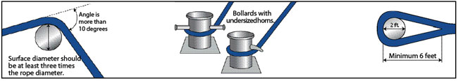
Sharp bends around any equipment should be avoided as, under load, it decreases rope strength substantially and may cause premature damage and failure. The diameter on fixed pin termination should be at least 3 times the rope diameter and on rotating sheave blocks, it should be 10 times the rope diameter for twisted ropes and 8 times the rope diameter for braided ropes.
Ropes should be stored on a clean and dry place without exposing them to the direct sunlight or any other potential substance or form that can cause damage to the rope.
It is advisable not to keep Ropes on the floor and should be kept at some distance away from metal walls or steam pipes to avoid the risk of possible corrosion or typical wear and tear.
To maintain the longevity of the ropes, it should never be stored on concrete and dirty floors and never dragged over rough surfaces as the dirt accumulated on the rope will cause damage to the inside fibers.
Working loads are the loads that a rope is subjected to when in activity. They are normally expressed as a percentage of new rope strength and should not exceed 20% of published strengths. (Many industries are subject to special working loads regulations that supersede a manufacturer’s recommendation.)
When severage due to overloaded or shock loads take place, the rope can suffer damages and consequently strength losses without any visible indication, which may weaken the rope and cause it to break during its next use even if used under normal working loads. Sharp bends should be avoided as, under load, it decreases rope strength substantially and can cause premature failure
All ropes should be protected against sharp and abrasive surface. Wire ropes tent to score and gouge chocks and bitts creating cutting edges that can damage synthetic ropes. Weld beads on repaired capstands, fairleads, etc. are equally damaging unless dressed down smoothly.

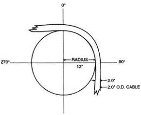
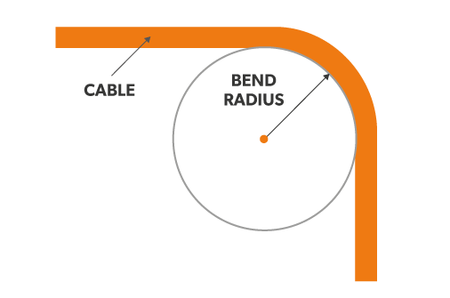
The bend radius is the radius at which a cable can be bent without damaging it (including kinking). The smaller the radius, the greater the required flexibility of the material. A frequently asked question in this context is: how much can we bend a cable without damaging it or impairing its function? The answer depends mainly on the particular cable being considered. There are several industry standards, such as IEEE 1185, ICEA S-75-381, ICEA S-66-524 or ICEA S-68-516, which provide minimal bend radii for many different cable types.
The minimum bend radius is the radius below which an object cannot be bent. In many installations, cable carriers are used, so the question arises: how do we select the bend radius of a cable or a cable carrier?
When deciding on a cable management system, there are several ways to extend the service life of the cable. One of the most important factors is the selection of the right bend radius for the cable carrier. It is important that the radius (except, perhaps, in space constrained applications) is greater than the recommended minimum bend radius of the cables. One of the key factors in long service life and operational reliability is choosing the right radius for the cable carrier. All cable carriers have several bend radii to choose from and each manufacturer proposes a minimum bend radius . The radius chosen for the cable carrier depends on the cable with the largest diameter.General rules and recommendations for selecting the radius
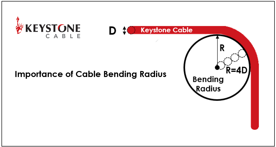
Do not exceed the manufacturer"s recommended minimum radius - but the maximum radius is optimal. Basically, cables with flexible specifications that move must be supported so that the connection points are not mechanically stressed and a sharp bend is avoided. If this is achieved by a loop, the cable must be provided with a bend radius of at least 10 times the diameter of the cable. The larger the radius, the less stress is exerted on the cables, which ensures a longer service life. It should be noted that the minimum bend radius is partially based on a temperature range for the bending. Particular care should be taken when the ambient temperature reaches or exceeds this temperature for the cable.
This is especially true for cryogenic applications where thermoplastic cables tend to stiffen when exposed to cold. Rigid cables can increase the radius of the cable carrier and lead to mechanical errors. It is recommended to use a cable with a PUR or TPE jacket at low temperature and/or to consult the manufacturer for recommendations on bend radii. For space constrained applications, the cable carrier radius must be less than the recommended minimum bend radius for the filling pack. This is not ideal, but if it cannot be avoided, cables designed specifically for low bend radius installations should be used. The igus chainflex range includes load-bearing control cables, servo and motor cables or robot cables as well as encoder cables, bus cables and data cables, which can be safely used in demanding environments and are characterised by their very long service life.
A long time ago when I was first running Ethernet cabling, I was told by an older installer that the best way to determine how much you could bend a cable was with a DVD/CD. He said the cable should not curve tighter than the outer edge of the disk. I thought this was a great rule of thumb! This was wise advice then, but a bit outdated today. Further, this was in the context of RG6 coaxial cable, a different animal than what we are talking about here.
Why should you be concerned with how much to bend an Ethernet cable (or any cable for that matter)? Think of your cable as a garden hose. Water should flow through it freely. Now, put a nice hard kink in that hose and the water stops. When discussing Ethernet cable, this is not a bad way of thinking about it. A kink, or too tight of a bend, can and does interfere with the signaling characteristics of the cable. The hose analogy is an extreme example as the water stops altogether. In the case of Ethernet cable the speeds at which devices connect may be reduced, or there may be consistent packet errors. Or even worse…intermittent and hard to track down packet errors.
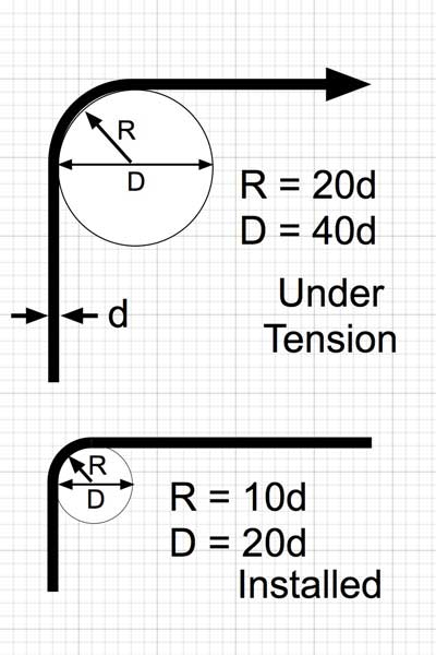
Arethere rules for how much you can bend Ethernet cable? Yes. According to ANSI/TIA-568-0.E, a manufacturer’s guidance around maximum bend radius trumps any generic guidelines. In absence of manufacturer stated rules, the generic guidance isfour times (4X)the cable jacket diameter for U/UTP Ethernet cable oreight times (8X)for F/UTP (and SF/FTP)solidcopper structure cable.
These rules change forstrandedcopper Ethernet patch cabling, however. Patch cables are held to the 4X rule, whether shielded or not. If you are confused about the difference between stranded and solid copper conductor cabling, see .
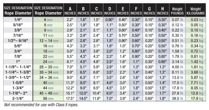
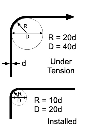
For trueCABLE U/UTP solid copper unshielded cable, we follow the ANSI/TIA guidelines. The inside radius of bends should be no tighter than 4X theouter diameter (OD) of the cable.For trueCABLE F/UTP solid copper shielded cable the inside radius of the cable should not be tighter than 7X the OD of the cable. See the table below for actual measurements, giving a far more useful dimension, the bend diameter.
If you are dealing with cable that is not trueCABLE brand, and that manufacturer provided no guidance around bend radius limitations,there is a nice little formula and it does not matter whether it is calculated in millimeters or inches. If the Ethernet cable has a specified OD published by the manufacturer, this formula is easy to apply.
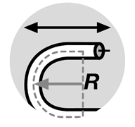
When putting this into practice, visualizing a bend radius is tough. Rather than rely upon bend radius to be your guide, rely on bend diameter. Bend diameter is simply calculated as:
The result is far easier to visualize. Diameter is the width of the inside of a circle. For an example of how this looks in practice, here are some pictures that may help.
I am sure many out there will provide stories about how much tighter they can bend a cable and get away with it. Sometimes, a sharper turn is simply unavoidable. My only advice is to obey the rules of thumb, but use common sense and don’t bend a cable at a right angle! Performance testing is the best way to confirm your cabling works as expected.
trueCABLE presents the information on our website, including the “Cable Academy” blog and live chat support, as a service to our customers and other visitors to our website subject to our website
The conductor shall not be bent to a radius less than eight times the overall diameter for non-shielded conductors or twelve times the diameter for shielded or lead-covered conductors during or after installation.
For the smaller sizes of ropes (below 12 mm) open thimble can be acceptable, but it has to be seized to the rope. In general we recommend using stainless tube thimbles and preferably with a gusset, which prevents the thimble from deformation.
Dyneema® is produced by DSM in the Netherlands. It is an ultra high molecular weight polyethylene (UHMWPE) or for short HMPE. It is superior to many other synthetic fibres in terms of weight, abrasion resistance, strength etc. Read more about HMPE/Dyneema® here.

Wire rope is also known by many other names, such as: wire, multi-strand wire, flexible wire, cable, cord, steelcord, etc. but it is essentially a collection of small filaments wound around each other in a manner that largely retains its shape when bent, crushed and/or tensioned.
It is a system for significantly increasing the strength and flexibility of steel wire and is used in almost every important application we see around us. For example: suspension bridges, tyres, brake and accelerator cables (in cars), high-pressure flexible pipes, lifting and rigging cables, electrical conductors, etc. and it comes in many different forms. Fig 2 shows just a very small sample of available designs.
With minor variations, the generally accepted method for designating a wire rope construction in the industry is by describing it numerically. For example:
"0.43+6x0.37+6x(0.37+6x0.33) HT" refers to a seven strand construction: a single central strand (one central filament diameter 0.43mm and 6 planetary filaments of diameter 0.37mm) and 6 planetary strands (one central filament of diameter 0.37mm and 6 planetary filaments of diameter 0.33mm) all manufactured from high-tensile steel"
Whilst "IWRC" wire ropes offer a slightly greater tensile capacity (≈7%) than those with fabric or polymer fillers, the additional strength does not come from the tensile capacity of the core filaments but from improved dimensional stability under load. And whilst they are also much more resistant to crushing, they are stiffer than fibre core ropes and therefore not recommended for applications where tension occurs under bending.
Warrington (Fig 1) is a parallel lay construction with an outer layer comprising wires of alternating large and small diameters, each outer layer having twice the number of wires as the layer immediately beneath. The benefit of this design is to increase packing and therefore strength density, however, unless the different diameter filaments are of the same strength (unlikely), this construction is limited by the strength of the weakest filaments.
Seale (Figs 1 & 2 6x36) is also a parallel lay construction but with the same number of wires in each wire layer. All the wires in any layer are the same diameter. This is an alternative to the Warrington construction, with similar benefits and disadvantages.
Tyrecord generally comprises a single strand of less than 1.5mm in diameter and normally contains about 12 filaments all of the same diameter between 0.15mm and 0.25mm, but designs and configurations can vary considerably dependent upon manufacturer and tyre design requirements. This design tends to be the most flexible of all constructions.
OTR is more or less a complicated tyrecord construction (see above) up to 4.5mm in diameter containing around 100 filaments of a similar size to tyrecord, albeit towards the larger end of the size range (0.2mm to 0.25mm).
Regular lay constructions are used much more widely (than Lang lay) because they have excellent structural stability and less tendency to unwrap under tension (see Rotating vs Non-Rotating below). However, because it has a knobbly (undulating) surface it will wear both itself and any surface over which it is run much more quickly than Lang lay wire rope.
Lang lay constructions have a flatter surface than regular lay constructions giving them better resistance to wear and bending fatigue, especially when made from flattened (elliptical) filaments. They are, however, much less structurally stable and subject to birdcaging if the wire rope is over-bent or twisted against its wrapped direction.
"Regular Lay", multi-strand constructions are normally subject to slightly less rotation under tension (than Lang lay) due to the opposite helical direction of the filaments (within the strands) and the strands (within the rope), however, you can improve their rotation characteristics still further by;
Whilst there are very distinct non-rotating constructions such as 19x7 and rotation-resistant designs such as 19x19, new ideas are evolving all the time and each manufacturer will have its own design preferences.
"Lang lay" and single strand (e.g. Fig 2 1x7) constructions will always try to straighten (unwrap) under tension. There are a number of things that could be done to minimise this problem, such as a) to c) above and/or;
Fillers (Fig 2) may be fabric, polymer or even smaller diameter filaments (e.g. 6x36). Whilst they contribute little to the tensile strength of wire rope, they can significantly; improve performance under bending (fabric and polymer cores only), reduce axial growth, reduce rotation in rotation-resistant constructions, improve structural stability and increase fatigue life.
There is little point in having a central core manufactured from the same material as the filaments as it will be the first to break. If you need a metal core, this should be of a material with lower axial stiffness than the strand that surrounds it.
This filler material should not be included in strength (tensile capacity) calculations, but must be included in those for axial stiffness (extension). If it is ignored, your calculations will reveal excessive extension as the wire rope collapses.
Suspension bridges tend to be constructed from densely packed, single strand plain "Wire Rope" constructions using large diameter galvanised filaments. Little heed is paid to rotational resistance as strength is paramount and once tensioned, they should remain in that loading condition for their design life.
Lifting & winching normally require wire ropes of good flexibility and fatigue resistance. Therefore they tend to be similar to 6x36 but with fibre core instead of the IWRC in Fig 2
Hosecord is suitable for HPHT flexible pipes as lateral flexibility is generally considered less important than minimal longitudinal growth or maximum tensile strength (per unit cross-sectional area).
Remote operating cables such as hand-brakes and accelerators on cars normally only work in tension so they need to be strong but not necessarily stiff (as they are fully contained in reinforced outer sheaths). These tend to be manufactured from large diameter "TyreCord" or small diameter single-strand "Wire Rope".
Axial stiffness is the linear relationship between axial strain and force that allows us to predict the condition of any material or structure when exposed to a specified tensile force. However, it works only with materials and structures that obey Hooke"s law.
Wire rope does not obey Hooke"s law. Therefore, you cannot accurately predict how much it will stretch for any specified force. This unpredictability applies to any section removed from the same manufactured length of cord and even between cords produced to the same specification but by different manufacturers.
CalQlata has decided that the accuracy of axial stiffness (EA) of wire rope falls outside its own levels of acceptability and therefore does not include it in the wire rope calculator. The extension calculated in the Wire Rope calculator (δLᵀ) is based upon the effect of axial tension on packing density. It is therefore important that core material is not ignored when using the calculator to evaluate this characteristic.
Torsional stiffness is the linear relationship that allows us to predict the rotation of any material or structure when exposed to a torque. However, it works only with materials and structures that obey Hooke"s law.
Wire rope does not obey Hooke"s law. Therefore, you cannot accurately predict how much it will twist for any specified torque. This unpredictability applies to any section removed from the same manufactured length of cord and even between cords produced to the same specification but by different manufacturers.
CalQlata has decided that the accuracy of torsional stiffness (GJ) of wire rope falls outside its own levels of acceptability and therefore does not include it in the wire rope calculator.
1) No wire rope calculator, whether dedicated or generic, will accurately predict the properties of any single construction under a wide range of loading conditions
2) No wire rope calculator, whether dedicated or generic, will accurately predict any single property for a range of constructions under a wide range of loading conditions
3) Unless additional heat treatment or material modification is performed during the manufacturing (drawing) process, the smaller the filament diameter the greater will be its SMYS
The only wire rope that can be reliably analysed is that which is used for suspension bridges, because; it comprises a single strand, is very densely packed, has negligible twist, contains filaments of only one diameter, is never subjected to minimum bending and every filament is individually tensioned.
There is a very good reason why manufacturers do not present calculated performance data for construction or design proposals, because even they cannot accurately predict such properties and quite rightly rely on, and publish, test data.
During his time working in the industry, the wire rope calculator"s creator has seen, created and abandoned numerous mathematical models both simple and complex. He has gradually developed his own simplified calculation principle based upon his own experience that still provides him with consistently reliable results of reasonable accuracy.
The purpose of CalQlata"s wire rope calculator is to provide its user with the ability to obtain a reasonable approximation for a generic construction, after which, accurate test data should be sought from the manufacturer for the user"s preferred construction.
The calculation principle in the wire rope calculator is based upon changes in the properties of the wire rope that occur with variations in packing density under tension
Bearing in mind the above limitations CalQlata can provide the following assistance when generating (manipulating) the wire rope calculator"s input data and interpreting its output
Alternatively, for wire rope with multiple filament diameters, you need to find an equivalent diameter with the following proviso; you must enter the minimum filament yield stress (SMYS)
It is expected that apart from fillers, all the material in the wire rope will be identical and therefore have the same density, i.e. using different materials will result in less than "best" performance. However, if such a construction is proposed, you can calculate an equivalent density as follows:
It is expected that apart from fillers, all the material in the wire rope will be identical and therefore have the same tensile modulus, i.e. using different materials will result in less than "best" performance. However, if such a construction is proposed, you should enter the highest tensile modulus.
The wire rope calculator simply adds together the total area of all the filaments and multiplies them by the SMYS entered, which represents a theoretical maximum breaking load that would exist if this load is equally shared across all of the filaments and the lay angles have been arranged to eliminate localised (point) loads between adjacent filaments.
If the wire rope has been properly constructed it is likely that its actual break load will be greater than 80% of this theoretical value. However, given the vagaries of wire rope construction, the actual break load can vary considerably dependent upon a number of factors. CalQlata suggest that the following factors may be used to define the anticipated break load of any given construction:
Accuracy is expected to be within ±0.1% of the calculated value for good quality manufacturing but variations in manufactured filament diameter can, in extreme cases, reduce this to ±1%
The axial stiffness and strain under load will be affected by this value, hence the reason why the most reliable (predictable) constructions tend to be minimum [number of] strands and single filament diameter. The Warrington and Seale constructions and combinations thereof tend to provide the highest packing density (but lowest flexibility) and there is little to be gained from using these constructions in more than single stranded wire rope as the benefit of high-packing density will be lost with no gain in flexibility.
The anticipated second moment of area of the wire rope at tension "T" due to deformation but insignificant flattening as it is assumed the wire rope will be bent over a formed (shaped) sheave or roller.
The anticipated tensile modulus of the wire rope at tension "T" due to deformation but insignificant flattening as it is assumed the wire rope will be bent over a formed (shaped) sheave or roller.
It is not advisable to induce this bend radius in operation due to uncertainties associated with wire rope construction, especially for dynamic applications. CalQlata suggests that a similar approach to that used for the break load (Fb) above also be applied here, i.e.:
A change in diameter will occur in all wire rope, irrespective of construction, until packing density has reached a limiting value. The value provided in the wire rope calculator is that which would be expected if the construction remains intact at the applied tension "T"
Unreliability of this value increases with complexity in wire rope due to its longitudinal variability and the increased likelihood of premature failure.
The accuracy of this data will range from about ±1% for wire rope with a single strand and a single filament diameter, up to about ±15% for constructions of similar complexity to OTR cord
A change in length of any wire rope will occur due to the fact that the packing density increases with tension. This is not, however, a linear relationship.
This can be an unreliable value as illustrated by tests carried out (by the author) on two pieces of wire rope supplied by the same well-known manufacturer both of which were cut from the same length, varied in tensile capacity by only 1.5%, but the tensile modulus (and strain at break) varied by 34%. Whilst this was an extreme case, significant variations have been seen in wire rope manufactured by a number of manufacturers.
Whilst the wire rope calculator does not calculate axial stiffness (see Calculation Limitations 9) above), CalQlata can suggest the following rule-of-thumb that will provide reasonable results for most constructions at the applied tension "T":
Where: θ = the "absolute" sum of the average filament lay angle and the average strand lay angle⁽²⁾. Note; the angle of twist (θ) will reduce as tension approaches break load.
Whilst the wire rope calculator does not calculate bending stiffness (see Calculation Limitations 8) above), CalQlata can suggest the following rule-of-thumb that will provide reasonable results for most constructions at the applied tension "T":
Low complexity means single strand and single wire diameter. Medium complexity means multi-strand and single wire diameter. High complexity means multi-strand and multiple wire diameters.
If the filament lay angle and the strand lay angle are in opposite directions, as with Regular Lay constructions, you must add the angles together as positives; i.e. -12° + 23° = 35°
Rope diameter is specified by the user and is generally given in the equipment manufacturer’s instruction manual accompanying the machine on which the rope is to be used.
Rope diameters are determined by measuring the circle that just touches the extreme outer limits of the strands— that is, the greatest dimension that can be measured with a pair of parallel-jawed calipers or machinist’s caliper square. A mistake could be made by measuring the smaller dimension.
The right way to unreel.To unreel wire rope from a heavy reel, place a shaft through the center and jack up the reel far enough to clear the floor and revolve easily. One person holds the end of the rope and walks a straight line away from the reel, taking the wire rope off the top of the reel. A second person regulates the speed of the turning reel by holding a wood block against the flange as a brake, taking care to keep slack from developing on the reel, as this can easily cause a kink in the rope. Lightweight reels can be properly unreeled using a vertical shaft; the same care should be taken to keep the rope taut.
The wrong way to unreel.If a reel of wire rope is laid on its flange with its axis vertical to the floor and the rope unreeled by throwing off the turns, spirals will occur and kinks are likely to form in the rope. Wire rope always should be handled in a way that neither twists nor unlays it. If handled in a careless manner, reverse bends and kinks can easily occur.
The right way to uncoil.There is only one correct way to uncoil wire rope. One person must hold the end of the rope while a second person rolls the coil along the floor, backing away. The rope is allowed to uncoil naturally with the lay, without spiraling or twisting. Always uncoil wire rope as shown.
The wrong way to uncoil.If a coil of wire rope is laid flat on the floor and uncoiled by pulling it straight off, spirals will occur and kinking is likely. Torsions are put into the rope by every loop that is pulled off, and the rope becomes twisted and unmanageable. Also, wire rope cannot be uncoiled like hemp rope. Pulling one end through the middle of the coil will only result in kinking.
Great stress has been placed on the care that should be taken to avoid kinks in wire rope. Kinks are places where the rope has been unintentionally bent to a permanent set. This happens where loops are pulled through by tension on the rope until the diameter of the loop is only a few inches. They also are caused by bending a rope around a sheave having too severe a radius. Wires in the strands at the kink are permanently damagedand will not give normal service, even after apparent “re-straightening.”
When wire rope is wound onto a sheave or drum, it should bend in the manner in which it was originally wound. This will avoid causing a reverse bend in the rope. Always wind wire rope from the top of the one reel onto the top of the other.Also acceptable, but less so, is re-reeling from the bottom of one reel to the bottom of another. Re-reeling also may be done with reels having their shafts vertical, but extreme care must be taken to ensure that the rope always remains taut. It should never be allowed to drop below the lower flange of the reel. A reel resting on the floor with its axis horizontal may also be rolled along the floor to unreel the rope.
Wire rope should be attached at the correct location on a flat or smooth-faced drum, so that the rope will spool evenly, with the turns lying snugly against each other in even layers. If wire rope is wound on a smooth-face drum in the wrong direction, the turns in the first layer of rope will tend to spread apart on the drum. This results in the second layer of rope wedging between the open coils, crushing and flattening the rope as successive layers are spooled.
A simple method of determining how a wire rope should be started on a drum. The observer stands behind the drum, with the rope coming towards him. Using the right hand for right-lay wire rope, and the left hand for left lay wire rope, the clenched fist denotes the drum, the extended index finger the oncoming rope.
Clips are usually spaced about six wire rope diameters apart to give adequate holding power. They should be tightened before the rope is placed under tension. After the load is placed on the rope, tighten the clips again to take care of any lessening in rope diameter caused by tension of the load. A wire rope thimble should be used in the eye of the loop to prevent kinking.
U-bolt Clips.There is only one correct method for attaching U-bolt clips to wire rope ends, as shown in TheRightWayimage below. The base of the clip bears on the live end of the rope; the “U” of the bolt bears on the dead end.
Compare this with the incorrect methods. Five of the six clips shown are incorrectly attached—only the center clip in the top view is correct. When the “U” of the clip bears on the live end of the rope, there is a possibility of the rope being cut or kinked, with subsequent failure.
Proper seizing and cutting operations are not difficult to perform, and they ensure that the wire rope will meet the user’s performance expectations. Proper seizings must be applied on both sides of the place where the cut is to be made. In a wire rope, carelessly or inadequately seized ends may become distorted and flattened, and the strands may loosen. Subsequently, when the rope is operated, there may be an uneven distribution of loads to the strands; a condition that will significantly shorten the life of the rope.
Either of the following seizing methods is acceptable. Method No. 1 is usually used on wire ropes over one inch in diameter. Method No. 2 applies to ropes one inch and under.
Method No. 1: Place one end of the seizing wire in the valley between two strands. Then turn its long end at right angles to the rope and closely and tightly wind the wire back over itself and the rope until the proper length of seizing has been applied. Twist the two ends of the wire together, and by alternately pulling and twisting, draw the seizing tight.
The Seizing Wire. The seizing wire should be soft or annealed wire or strand. Seizing wire diameter and the length of the seize will depend on the diameter of the wire rope. The length of the seizing should never be less than the diameter of the rope being seized.
Proper end seizing while cutting and installing, particularly on rotation-resistant ropes, is critical. Failure to adhere to simple precautionary measures may cause core slippage and loose strands, resulting in serious rope damage. Refer to the table below ("Suggested Seizing Wire Diameters") for established guidelines. If core protrusion occurs beyond the outer strands, or core retraction within the outer strands, cut the rope flush to allow for proper seizing of both the core and outer strands.
The majority of wire rope problems occurring during operation actually begin during installation, when the rope is at its greatest risk of being damaged. Proper installation procedures are vital in the protection and performance of wire rope products.
Until the rope is installed it should be stored on a rack, pallet or reel stand in a dry, well-ventilated storage shed or building. Tightly sealed and unheated structures should be avoided as condensation between rope strands may occur and cause corrosion problems. If site conditions demand outside storage, cover the rope with waterproof material and place the reel or coil on a support platform to keep it from coming directly in contact with the ground.
While lubrication is applied during the manufacturing process, the wire rope must still be protected by additional lubrication once it is installed. Lubricants will dry out over a period of time and corrosion from the elements will occur unless measures are taken to prevent this from happening. When the machine becomes idle for a period of time, apply a protective coating of lubricant to the wire rope. Moisture (dew, rain, and snow) trapped between strands and wires will create corrosion if the rope is unprotected. Also apply lubricant to each layer of wire rope on a drum because moisture trapped between layers will increase the likelihood of corrosion.
Always use the nominal diameter as specified by the equipment manufacturer. Using a smaller diameter rope will cause increased stresses on the rope and the probability of a critical failure is increased if the rated breaking strength does not match that of the specified diameter. Using a larger diameter rope leads to shorter service life as the rope is pinched in the sheave and drum grooves which were originally designed for a smaller diameter rope. Just as using a different diameter rope can create performance problems, so can the use of an excessively undersized or oversized rope.
Measure the wire rope using a parallel-jawed caliper as discussed in Measuring Rope Diameter at the top of this page. If the rope is the wrong size or outside the recommended tolerance, return the rope to the wire rope supplier. It is never recommended nor permitted by federal standards to operate cranes with the incorrect rope diameter. Doing so will affect the safety factor or reduce service life and damage the sheaves and drum. Note that in a grooved drum application, the pitch of the groove may be designed for the rope’s nominal diameter and not the actual diameter as permitted by federal standards.
Wire rope can be permanently damaged by improper unreeling or uncoiling practices. The majority of wire rope performance problems start here.Improper unreeling practices lead to premature rope replacement, hoisting problems and rope failure.
Place the payout reel as far away from the boom tip as is practical, moving away from the crane chassis. Never place the payout reel closer to the crane chassis than the boom point sheave. Doing so may introduce a reverse bend into the rope and cause spooling problems. Follow the guidelines highlighted under Unreeling and Uncoiling and Drum Winding. Take care to determine whether the wire rope will wind over or under the drum before proceeding. If the wire rope supplier secured the end of the rope to the reel by driving a nail through the strands, ask that in the future a U-bolt or other nondestructive tie-down method be used; nails used in this manner damage the rope.
Take extra precaution when installing lang lay, rotation-resistant, flattened strand or compacted ropes. Loss of twist must be avoided to prevent the strands from becoming loosened, causing looped wire problems.
The end of the rope must be securely and evenly attached to the drum anchorage point by the method recommended by the equipment manufacturer. Depending on the crane’s regulatory requirements, at least two to three wraps must remain on the drum as dead wraps when the rope is unwound during normal operations. Locate the dead end rope anchorage point on the drum in relation to the direction of the lay of the rope. Do not use an anchorage point that does not correspond with the rope lay. Mismatching rope lay and anchorage point will cause the wraps to spread apart from each other and allow the rope to cross over on the drum. Very gappy winding will occur resulting in crushing damage in multilayer applications.
Back tension must be continually applied to the payout reel and the crewman installing the rope must proceed at a slow and steady pace whether the drum is smooth or grooved.Regardless of the benefits of a grooved drum, tension must be applied to ensure proper spooling. An improperly installed rope on a grooved drum will wear just as quickly as an improperly installed rope on a smooth drum. If a wire rope is poorly wound and as a result jumps the grooves, it will be crushed and cut under operating load conditions where it crosses the grooves.
Every wrap on the first or foundation layer must be installed very tightly and be without gaps. Careless winding results in poor spooling and will eventually lead to short service life. The following layers of rope must lay in the grooves formed between adjacent turns of the preceding layer of rope. If any type of overwind or cross-winding occurs at this stage of installation and is not corrected immediately, poor spooling and crushing damage will occur.
On a multilayer spooling drum be sure that the last layer remains at least two rope diameters below the drum flange top. Do not use a longer length than is required because the excess wire rope will cause unnecessary crushing and may jump the flange. Loose wraps that occur at any time must be corrected immediately to prevent catastrophic rope failure.
The use of a mallet is acceptable to ensure tight wraps, however a steel-faced mallet should be covered with plastic or rubber to prevent damage to the rope wires and strands.
Rotation-resistant ropes of all constructions require extra care in handling to prevent rope damage during installation. The lay length of a rotation-resistant rope must not be disturbed during the various stages of installation. By introducing twist or torque into the rope, core slippage may occur—the outer strands become shorter in length, the core slips and protrudes from the rope. In this condition the outer strands become over- loaded because the core is no longer taking its designed share of the load. Conversely, when torque is removed from a rotation-resistant rope core slippage can also occur. The outer strands become longer and the inner layers or core become overloaded, reducing service life and causing rope failure.
The plain end of a wire rope must be properly secured. If the entire cross section of the rope is not firmly secured, core slippage may occur, causing the core to pull inside the rope’s end and allowing it to protrude elsewhere, either through the outer strands (popped core) or out the other end of the line. The outer layer of the outside strands may also become overloaded as there is no complete core-to-strand support.
Secure the ends of the rope with either seizing or welding methods as recommended under Seizing Wire Rope. It is imperative that the ends be held together tightly and uniformly throughout the entire installation procedure, including attaching the end through the wedge socket and the drum dead end wedge
When installing a new line, connect the old line to the new line by using a swivel-equipped cable snake or Chinese finger securely attached to the rope ends. The connection between the ropes during change-out must be very strong and prevent torque from the old rope being transferred into the new rope.Welding ropes together or using a cable snake without the benefit of a swivel increases the likelihood of introducing torque into the new rope. A swivel-equipped cable snake is not as easy as welding the ropes, but this procedure can be mastered with a little patience and practice.


 8613371530291