
what is the safety factor of wire rope sling free sample

Wire ropes are essential for safety purposes on construction sites and industrial workplaces. They are used to secure and transport extremely heavy pieces of equipment – so they must be strong enough to withstand substantial loads. This is why the wire rope safety factor is crucial.
You may have heard that it is always recommended to use wire ropes or slings with a higher breaking strength than the actual load. For instance, say that you need to move 50,000 lbs. with an overhead crane. You should generally use equipment with a working load limit that is rated for weight at least five times higher – or 250,000 lbs. in this case.
This recommendation is all thanks to the wire rope safety factor. This calculation is designed to help you determine important numbers, such as the minimum breaking strength and the working load limit of a wire rope.
The safety factor is a measurement of how strong of a force a wire rope can withstand before it breaks. It is commonly stated as a ratio, such as 5:1. This means that the wire rope can hold five times their Safe Work Load (SWL) before it will break.
So, if a 5:1 wire rope’s SWL is 10,000 lbs., the safety factor is 50,000 lbs. However, you would never want to place a load near 50,000 lbs. for wire rope safety reasons.
The safety factor rating of a wire rope is the calculation of the Minimum Break Strength (MBS) or the Minimum Breaking Load (MBL) compared to the highest absolute maximum load limit. It is crucial to use a wire rope with a high ratio to account for factors that could influence the weight of the load.
The Safe Working Load (SWL) is a measurement that is required by law to be clearly marked on all lifting devices – including hoists, lifting machines, and tackles. However, this is not visibly listed on wire ropes, so it is important to understand what this term means and how to calculate it.
The safe working load will change depending on the diameter of the wire rope and its weight per foot. Of course, the smaller the wire rope is, the lower its SWL will be. The SWL also changes depending on the safety factor ratio.
The margin of safety for wire ropes accounts for any unexpected extra loads to ensure the utmost safety for everyone involved. Every year there aredue to overhead crane accidents. Many of these deaths occur when a heavy load is dropped because the weight load limit was not properly calculated and the wire rope broke or slipped.
The margin of safety is a hazard control calculation that essentially accounts for worst-case scenarios. For instance, what if a strong gust of wind were to blow while a crane was lifting a load? Or what if the brakes slipped and the load dropped several feet unexpectedly? This is certainly a wire rope safety factor that must be considered.
Themargin of safety(also referred to as the factor of safety) measures the ultimate load or stress divided by theallowablestress. This helps to account for the applied tensile forces and stress thatcouldbe applied to the rope, causing it to inch closer to the breaking strength limit.
A proof test must be conducted on a wire rope or any other piece of rigging equipment before it is used for the first time.that a sample of a wire rope must be tested to ensure that it can safely hold one-fifth of the breaking load limit. The proof test ensures that the wire rope is not defective and can withstand the minimum weight load limit.
First, the wire rope and other lifting accessories (such as hooks or slings) are set up as needed for the particular task. Then weight or force is slowly added until it reaches the maximum allowable working load limit.
Some wire rope distributors will conduct proof loading tests before you purchase them. Be sure to investigate the criteria of these tests before purchasing, as some testing factors may need to be changed depending on your requirements.
When purchasing wire ropes for overhead lifting or other heavy-duty applications, understanding the safety dynamics and limits is critical. These terms can get confusing, but all of thesefactors serve an important purpose.
Our company has served as a wire rope distributor and industrial hardware supplier for many years. We know all there is to know about safety factors. We will help you find the exact wire ropes that will meet your requirements, no matter what project you have in mind.
Safe Working Load (SWL) is the limiting safety factor to lift and carry any load safely. It must be clearly marked on any lifting device (hoist, lifts, lifting machines, and lifting tackles).
“No lifting machine and no chain, rope or lifting tackle shall, except for the purpose of the test, be loaded beyond the safe working load which shall be plainly marked and duly entered in the prescribed register, and where this is not practicable, a table showing the safe working loads of every kind and size of lifting machine or chain, rope or lifting tackle in use shall be displayed in prominent positions on the premises”
Where the safe working load may be varied by the raising or lowering of the jib, a table indicating the SWL at the corresponding indication of the jib or corresponding radii of the load shall be attached with the jib-crane.
A table showing the SWL (Safe Working Load) of every kind and size of chain, rope, or lifting tackle in use, and in case of multiple slings, the SWLat different angles of the legs, shall be posted in the storeroom.
Lifting equipment should have a tally plate indicating the Safe Working Load. The tally plate also indicates the identification number which can be mentioned in the test certificate held by the user. It should also indicate the date of the last inspection.
Safe Working Load (SWL) of any mobile crane depends on the operator’s skill, condition of the ground, boom length, the radius of rotation while lifting the load, the inclination of the boom to the vertical and outrigger blocked or free.
Safe Working Load is generally tabulated in the load chart of the crane. Sometimes, it is de-rated(decreased) due to defect in welding, bend in angle, bracing, etc., and condition of clutch, brake, etc. Modern cranes give a digital display of SWL, angle indicator, boom limit switch, and alarm for exceeding load.
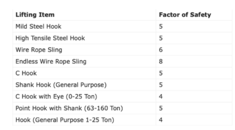
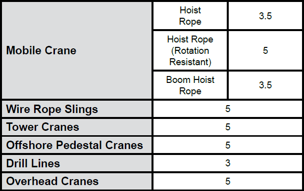
The factor of the safety (Safety Factor) of fiber ropes varies from 6 to 12 mm depending on the conditions of use. fiber rope less than 12 mm dia should not be used for a sling or apart of a lifting appliance. Their factor of safety (FS) varies with diameter. The factor of Safety for the hook, wire rope sling, chain, fiber rope, and belt are given in the table below:
Proof testing is the application of a load greater than the SWL (Safe Working Load) to detect defective workmanship, faulty weld or other inherent weaknesses. It is not a means to assess the SWLwhich should only be done by calculations and checked where necessary by suitable tests on samples.
The proof test is required as a part of ‘thorough examination’ u/r 60(1) of GFRand no lifting machine or tackle should be used for the first time without this proof test.
In general, the proof load applied to chains, rings, hooks, shackles, and similar gear is twice the SWL. It should be just under the yield stress for the material.
Chain, ring, hook, shackles, swivel, sling, individual components of the hoist, wire rope, chain, pulleys, hooks, eye bolts, pins, axles, bearings, turnbuckles & ringing screws.2 SWL
After the above proof test, the parts are to be examined thoroughly by a competent person for signs of cracks, fatigue, deformation, permanent stretch, etc.

Wire rope is often used in slings because of its strength, durability, abrasion resistance and ability to conform to the shape of the loads on which it is used. In addition, wire rope slings are able to lift hot materials.
Wire rope used in slings can be made of ropes with either Independent Wire Rope Core (IWRC) or a fiber-core. It should be noted that a sling manufactured with a fiber-core is usually more flexible but is less resistant to environmental damage. Conversely, a core that is made of a wire rope strand tends to have greater strength and is more resistant to heat damage.
Wire rope may be manufactured using different rope lays. The lay of a wire rope describes the direction the wires and strands are twisted during the construction of the rope. Most wire rope is right lay, regular lay. This type of rope has the widest range of applications. Wire rope slings may be made of other wire rope lays at the recommendation of the sling manufacturer or a qualified person.
Wire rope slings are made from various grades of wire rope, but the most common grades in use are Extra Improved Plow Steel (EIPS) and Extra Extra Improved Plow Steel (EEIPS). These wire ropes are manufactured and tested in accordance with ASTM guidelines. If other grades of wire rope are used, use them in accordance with the manufacturer"s recommendations and guidance.
When selecting a wire rope sling to give the best service, consider four characteristics: strength, ability to bend without distortion, ability to withstand abrasive wear, and ability to withstand abuse.
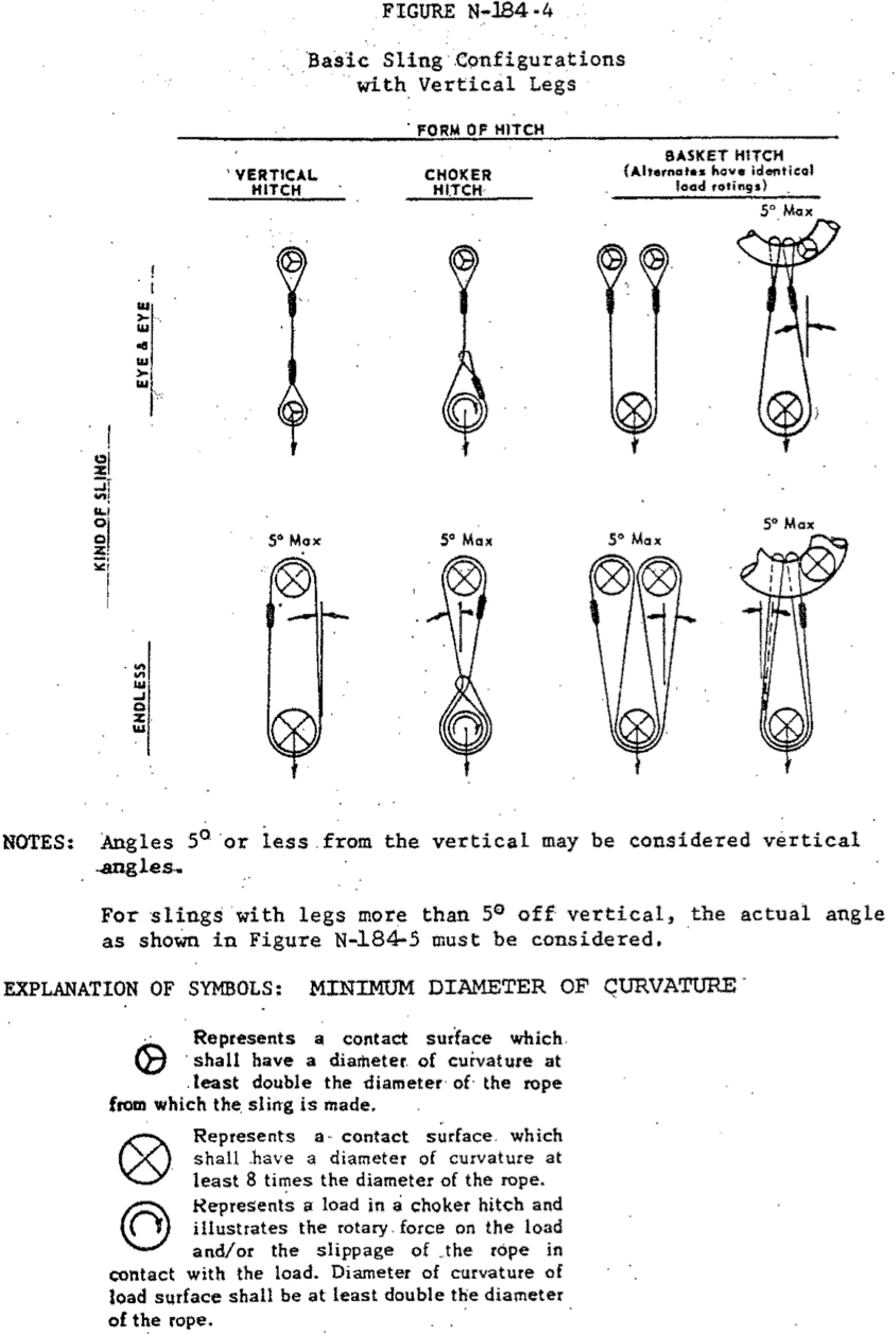
Rated loads (capacities) for single-leg vertical, choker, basket hitches, and two-, three-, and four-leg bridle slings for specific grades of wire rope slings are as shown in Tables 7 through 15.
Rated loads for a sling in a choker hitch are the values shown in Table 7, 9, 11, 13, 14, or 15, provided that the angle of the choke is 120 degrees or more (Fig. 2). Use the values in Fig. 2 or those from the sling manufacturer or a qualified person for angles of choke less than 120 degrees.
Ensure that slings made of rope with 6×19 and 6x37 classifications and cable slings have a minimum clear length of rope 10 times the component rope diameter between splices, sleeves, or end fittings unless approved by a qualified person,
Ensure that braided slings have a minimum clear length of rope 40 times the component rope diameter between the loops or end fittings unless approved by a qualified person,
Ensure that grommets and endless slings have a minimum circumferential length of 96 times the body diameter of the grommet or endless sling unless approved by a qualified person, and
Perform welding of handles or other accessories to end attachments, except covers to thimbles, before assembly of the sling. Ensure that welded end attachments are proof tested by the manufacturer or a qualified person. Retain the certificates of proof test and make them available for examination.
Do not use wire rope clips to fabricate wire rope slings, except where the application precludes the use of prefabricated slings and where the sling is designed for the specific application by a qualified person,
Although OSHA"s sling standard does not require you to make and maintain records of inspections, the ASME standard contains provisions on inspection records.[3]
Use damaged slings only after they are repaired, reconditioned, and proof tested by the sling manufacturer or a qualified person using the following criteria:
Ensure that wire rope slings have suitable characteristics for the type of load, hitch, and environment in which they will be used and that they are not used with loads in excess of the rated load capacities described in the appropriate tables. When D/d ratios (Fig. 4) are smaller than those listed in the tables, consult the sling manufacturer. Follow other safe operating practices, including:
Ensure that multiple-leg slings are selected according to Tables 7 through 15 when used at the specific angles given in the tables. Ensure that operations at other angles are limited to the rated load of the next lower angle given in the tables or calculated by a qualified person,
When D/d ratios (see Fig. 6) smaller than those cited in the tables are necessary, ensure that the rated load of the sling is decreased. Consult the sling manufacturer for specific data or refer to the WRTB (Wire Rope Technical Board) Wire Rope Sling Users Manual, and
Ensure that all portions of the human body are kept away from the areas between the sling and the load and between the sling and the crane or hoist hook,
When using a basket hitch, ensure that the legs of the sling contain or support the load from the sides, above the center of gravity, so that the load remains under control,
Ensure that the load applied to the hook is centered in the base (bowl) of the hook to prevent point loading on the hook, unless the hook is designed for point loading,
Before initial use, ensure that all new swaged-socket, poured-socket, turnback-eye, mechanical joint grommets, and endless wire rope slings are proof tested by the sling manufacturer or a qualified person.
Permanently remove from service fiber-core wire rope slings of any grade if they are exposed to temperatures in excess of 180 degrees F (82 degrees C).
Follow the recommendations of the sling manufacturer when you use metallic-core wire rope slings of any grade at temperatures above 400 degrees F (204 degrees C) or below minus 40 degrees F (minus 40 degrees C).
1. The proof testing of slings is the responsibility of the sling manufacturer or equivalent entity as delineated by the standard at 29 CFR 1910.184(e)(4), (g)(5), and (i)(8)(ii). The employer shall retain a "certificate of proof test" and shall make it available for examination by OSHA compliance officers.
It is believed that any proof load testing of workplace slings by other than the manufacturer or equivalent entity is an unacceptable loading and would necessitate that the sling be taken out of service unless written permission to test is obtained form the sling manufacturer. Users of slings must not exceed the sling manufacturer"s specifications and requirements pertaining to use and loadings.
The requirements imposed by the Boeing Company upon their subcontractors to repeatedly proof test slings to two (2) times rated load is not a recognized inspection procedure under the OSHA standards and would be a violation of 29 CFR 1910.184 (c)(4). However, should the sling manufacturer provide written permission to test the slings on a regular basis to a load greater than the designated working load, OSHA could consider the violation de minimus. Of course the procedures for such testing would also need to comply with the manufacturer"s recommendations.
The repeated testing of spreader bars and similar equipment seems to provide little more assurance of continued reliability than the visual inspections required by the various standards, including OSHA"s. Properly conducted visual inspections together with the careful reporting of misuse and various damaging exposures will provide for the continued reliability of the lifting equipment. Should periodic load testing be desired, it is recommended that slings be returned to the manufacturer or equivalent entity for the conduct of detailed inspection and load tests.
4. Certification is exclusively the right of only the manufacturer of new slings. Repaired slings may be certified by an equivalent entity who made the repairs.
Per our telephone conversation on the subject matter, I would like to request of Federal OSHA a review of the enclosed documents and give me your comments on their requirements.
The Boeing Company is quoting out of the WYOSHA General Rules and Regulations, 1910 Chapter 14, Section 7, Paragraph (a) and (b) for the justification to load test synthetic web slings to 200% (2X rated load). This reference deals with repair of synthetic web slings. We do not do any repair on web slings. If they are bad the slings are removed from service and destroyed.
100.9.4.1 Metallic slings and chokers and synthetic web slings - conduct 200% (2 x Rating) proofload test before placing in service and every 90 days thereafter with comprehensive inspection every 90 days. (Handwritten next to the above - Here is what Boeing requires per the safety requirements document.)
100.9.4.2 Non-metallic rope slings and chokers - conduct 100% (1 x Rating) proofload test before placing in service and every 90 days thereafter with comprehensive inspection every 90 days.
100.9.4.3 Shackles, turnbuckles, eyebolts, swivel ring bolts, hoist rings, and other metallic hardware - conduct 200% proofload test before placing in service.
1009.4.4 Special lifting fixtures and accessories designed for lifting specific materials, assemblies, or equipment such as large lifting fixtures, specially designed slings and spreader bars shall be 200% load tested (2 x Rating) annually with comprehensive inspection every 90 days.
100.9.4.5 Hoist anchorage including lift eyes, pad eyes, eyebolts, and swivel ring bolts, for support of portable hoists such as block and tackle, chain falls and come-a-longs shall be 125% load tested (1.25 x Rating) prior to first use and after rework with comprehensive inspection every 90 days.
100.9.4.6 Overhead hoists/cranes, trolley/monorail and portable chain hoists shall be 125% load tested (1.25 x Rating) prior to first use, after rework, and annually thereafter with written, dated signed comprehensive inspection every 30 days covering hooks, ropes, and brakes.
This letter and the attached copy of certification are in response to your inquiry of the above date through our distributor"s sales representative, (Aviation Industrial Supply). All of our nylon lifting slings meet or exceed all industry and OSHA standards. The rated capacity as listed on the leather identification tag and in our sales literature is based on a 5 to 1 safety factor as all slings are supposed to be.
When nylon lifting slings are "proof-tested" for the purposed of certification they are pulled at the respective bearing points, (at the eyes in a type 3 sling or at the triangles in a type 1 or 2 sling), to twice the rated "vertical" working capacity. We are completely confident in the manufacturing techniques and stitch methods employed in our slings and do regularly test random batches to assure continuing quality control.
If you desire proof-testing for any of our slings we can accommodate you at a nominal testing charge. Sling certifications are free of charge. Attached is a copy of our certification form. If we can be of any further service please contact us or Aviation Industrial Supply.
IT IS HEREBY CERTIFIED THAT THE MATERIAL AND/OR MANUFACTURED ARTICLE(S) FURNISHED ON THE INDICATED CONTRACT PURCHASE ORDER IS (ARE) IN CONFORMANCE WITH THE REQUIREMENTS, SPECIFICATIONS, AND DRAWINGS APPLICABLE TO THIS ORDER. PHYSICAL AND CHEMICAL DATA PERTAINING TO THIS ORDER (WHEN APPLICABLE) HAS BEEN FURNISHED AS REQUESTED. ALL MATERIALS, ASSEMBLIES, PROCESSES AND FINISHES USED ARE WITH-IN THE REQUIRED SPECIFICATIONS AND MEET INSPECTION TESTS AS CALLED FOR, PRIOR TO SHIPMENT.
On a previous occasion you contacted this agency with regard to load testing synthetic slings at 200 percent their rated capacity. At that time you were given a copy of the Wyoming Occupational Health and Safety rules for Construction. The specific standard that you were shown then , and still should take into account, is Chapter VIII, Section 2.e.(2) which states, "Rated capacity shall not be exceeded."
Section 2.e.(1),(a),(b), and (c) requires that the employer shall have each synthetic web sling marked or coded to show the name or trademark of the manufacturer, rated capacities for the type of hitch, type of material. This would give anyone using the sling all of the pertinent information required to use it safely.
Section 2.a.(1) of the same chapter states that "Rigging equipment for material handling shall be inspected prior to use on each shift, and as necessary during its use, to ensure that it is safe. Defective rigging equipment shall be removed from service." This rule is to assure that any type of rigging equipment is inspected before each shift that it would be used on and replaced if there is a problem with it.
The only place that load testing of rigging equipment is required is under Section 2.a.(4) which states, "Special custom design grabs, hooks, clamps, or other lifting accessories, for such units as modular panels, prefabricated structures and similar materials, shall be marked to indicate the safe working loads and shall be proof-tested prior to use to 125 percent of their rated load." This rule requires load testing only of special custom-designed equipment, not slings, and not on a monthly cycle but only a one-time test.
After reviewing the above stated rules, it would be this agency"s contention that any sling load tested to 200 percent of its rated capacity would be overloading the sling. With Section 2.e.(2) that sling would have to be removed from service due to the fact that the working capacity of the sling would not be known after such a tremendous amount of overloading has occurred.
Mr. Neil Blooding has objected to the periodic proof load test load of 200% of safe working load (SWL), required by reference (c), as being excessive and damaging to the sling. Mr. Blooding maintains that the proof load is limited by reference (b), which states "Rigging equipment shall not be loaded in excess of its recommended safe working load...". This position was collaborated with the Wyoming Occupational Safety and Health office in reference (a).
It is our contention that the intent of the quoted requirement is to prohibit lifting working loads which exceed the rated load capacity of the sling. It does not apply to loads used in proof testing.
The Boeing Proof Test load requirement for synthetic web slings is twice the rated capacity (200% SWL), as specified in reference (c). This is confirmed as an OSHA standard by the reference (d) letter.
The claim has been made that proof load testing every 90 days will cause damage to the sling form the effect of fatigue. This claim is invalid based on the following information:
1. Boeing performed tests on nylon web slings, reference (e), which showed that nylon web slings did not experience any significant loss of strength under repetitive loading even with loads exceeding the rated breaking strength of the webbing by 10 percent. This loading would be equivalent to a proof load of 550% SWL.
2. Breaking strength of the test samples was first determined by testing eleven samples to destruction. The breaking strength of the weakest sample was 124% of the rated breaking strength; average was 130% of rated breaking strength (650% SWL); indicating that the webbing more than met the legal requirement for strength.
3. The test samples were subjected to 13 to 16 repeated loads of 110% of rated breaking strength (550% SWL) without allowing time between loads for recovery, then pulled to destruction. This was considered a very severe test, as the nylon was not allowed to cool after being heated by the energy developed by the applied load. Single load tests would not be this severe. Final breaking strengths ranged from 121% to 132% of rated breaking strength. Average was 126% of rated breaking strength.
4. To simulate the effect of periodic proofload testing, nine samples were loaded to 120% of rated breaking strength (600% SWL) four times, allowing a recovery period of one day between loadings, then pulled to destruction. The weakest of these samples developed 128% of rated breaking strength; the strongest, 130% of rated break. Average was 129% of rated strength (645% SWL). This was 99% of the average strength of the original unloaded samples.
2. Proof testing at 200% SWL repeated every 90 days will have no detrimental effect on the strength of the sling. Tests conducted by Boeing have shown that nylon web slings can withstand severe and frequent repeated tests at loads of over 550% SWL with a strength loss of less than 2 percent.
The Boeing requirements as currently written comply with the intent of OSHA and will not be changed at this time. Questions may be addressed to Larry Pierce on (206) 395-1976, M/S 1E-62.
Examine slings for wear, fatigue, crushed or broken wires, kinking, ballooning or "bird-caging", heat damage, etc. Check both before and after using slings to detect any damage or defects. See Hoist wire rope for more inspection tips.

Provided that you follow all the way through the calculations regarding catenary action, specify the cable sag and/or pretension requirements and that anyone using the lifeline will be equipped with lanyard/shock absorbers etc. that meet ANSI/CSA requirements or the appropriate standards where you are, the factor of safety of 2 is the typical standard. Note, this is not a factor of safety of 2 on the 5000lb minimum anchorage requirement, as that is for a single point tie off and irrelevant for horizontal lifelines. A load factor of 5 could be high or low depending on what you are applying the factor to.
This is not a "proof is in the pudding" issue. Every lifeline used in the construction industry is designed for a factor of safety of 2. A factor of safety of 2 is both the codified value and standard practice.
The purpose of this safety policy and procedure is to establish the methods and guidelines for the safe use of slings throughout [COMPANY]. Slings, a component of hoisting and rigging systems, are used to lift and move loads. In [COMPANY], alloy steel chain, wire rope, natural and synthetic fiber rope, and synthetic web slings are typically used. Slings are capable of lifting tremendous loads.
This safety policy and procedure provides guidelines for implementing an effective safe sling use program. It includes provisions for training, recognizing the types of slings used in [COMPANY], understanding the attachments used with slings, and inspecting slings. Additionally, it presents information on sling repair requirements and subsequent removal from service.
It is the policy of [COMPANY] is to provide a place of employment free from recognized hazards that cause or are likely to cause death or serious physical harm to employees or the public. Therefore, to minimize and eliminate material lifting hazards, properly rated slings that are not damaged or defective will be used in [COMPANY]. When hazards exist that cannot be eliminated, then engineering practices, administrative practices, safe work practices, Personal Protective Equipment (PPE), and proper training regarding Slings will be implemented. These measures will be implemented to minimize those hazards to ensure the safety of employees and the public.
It is the responsibility of each manager/unit head, supervisor and employee to ensure implementation of [COMPANY]’s safety policy and procedure on Slings. It is also the responsibility of each [COMPANY] employee to report immediately any unsafe act or condition of equipment to his or her supervisor.
Managers/Unit Heads are responsible for ensuring adequate funds are available for the purchase of chains and slings for their areas. They will also be responsible for identifying the employees affected by this safety policy and procedure. Managers/Unit Heads will obtain and coordinate the required training for the affected employees. Managers/Unit Heads will also audit their safe sling use program to ensure effective implementation with this safety policy and procedure.
Supervisors. Every six months, supervisors or a designated employee will inspect all slings in their work area for wear and for defects in composition and welds. Supervisors will ensure that defective or damaged slings are removed from service. Supervisors will also ensure that employees are provided with the appropriate Personal Protective Equipment (PPE) as necessary for their job (e.g., foot, hand, or eye protection as necessary).
Employees shall comply with all applicable training. Additionally, employees shall report all damaged slings and/or unsafe conditions to their supervisors.
Safety and Loss Control. Safety and Loss Control will provide prompt assistance to managers/unit heads, supervisors, or others as necessary on any matter concerning this safety policy and procedure. Additionally, Safety and Loss Control will assist in developing or securing the required training. Safety and Loss Control will work with Purchasing to ensure that all newly purchased slings comply with this safety policy and procedure. Additionally, Safety will provide consultative and audit assistance to ensure the safe use of slings.
Central Equipment unit shall maintain an adequate supply of appropriate slings. Central Equipment Unit will ensure that all components are delivered with the appropriate manufacturer’s certification.
The user should determine that the sling is being used in accordance with rated capacity as listed in the manufacturer’s catalog. The alloy steel chain, wire rope and fiber rope slings are typically used where sling damage to the load is not critical. Synthetic web slings are ideal where sling damage to a load is not acceptable.
Alloy chain slingswill have permanent identification affixed to the sling indicating the size, grade, rated capacity, and reach of the sling. Untagged slings will be removed from service. Alloy steel chains and chain slings should not be heated above 600 degrees after being received from the manufacturer.
Wire rope slings must be proof-tested by the manufacturer to ensure quality. A certificate verifying rated capacity will accompany each wire rope sling. This certificate must be available for review.
Synthetic web slings must be marked or coded to show the rated capacities for each type of hitch, type of web material, and manufacturer. Additionally, synthetic web slings must not be exposed to fumes, vapors, sprays, mists, liquid acids, liquid phenolics, or liquid caustics.
Equipment Inspections are conducted to ensure specific safety equipment is in good working order and will function when needed. Examples and frequencies are:
All attachments including hooks, rings, oblong links, pear shaped links, and welded link components will be rated at least at the capacity of the sling itself. Makeshift links or other shop fabricated attachments will not be used. Slings twisted more than 10 degrees from the plane of the unbent hook will not be used.
Slings will be inspected each day prior to use. Any visual defect will be reported. Damaged slings will not be used. In severe conditions (e.g., temperature, corrosion, etc.), slings will be inspected throughout the day. Alloy chain slings will be inspected every six months by a supervisor or designated employee for wear and defects in composition and welds. This inspection will consider not only the physical aspects, but also the total service life of the slings. This inspection will be recorded and maintained on file with the date of the inspection and name and signature of the employee performing the inspection.
Slings must be in good condition and not damaged or defective to ensure safe and reliable use. If slings are worn, damaged or defective they shall not be used. If the slings are believed to be repairable, then those slings will be returned to the sling manufacturer for repairs. The manufacturer must proof-test all repaired slings before they are accepted for reuse. Under no circumstances will employees attempt to repair slings for reuse. Broken links or attachments on steel alloy chain slings will not be repaired using mechanical coupling links. Additionally, any sling with temporary repairs will not be used.
If slings are damaged or defective, they shall not be used. Until repairs are made on defective or damaged slings, they will be removed from service. If these slings are not repairable, they will be permanently removed from service. Appendix G lists the conditions that must be present to remove any sling from service.
• In manila rope, eye splices will consist of at least three full tucks, and short splices will consist of at least six full tucks, three on each side of the splice center line.
• In synthetic rope, eye splices will consist of at least four full tucks, and short splices will consist of at least eight full tucks, four on each side of the center line.
• Strand end tails will not be trimmed flush with the surface of the rope immediately adjacent to the full tucks. This applies to all types of fiber rope and both eye and short splices. For fiber rope under one inch in diameter, the tail will project at least six inches beyond the last full tuck.
• For all eye splices, the eye will be large enough to provide an angle of not greater than 60% at the splice when the eye is placed over the load or support.
The following information is to be used as a guide for inspecting wire rope and wire rope slings. Inspection frequency should be based on safety factors, property damage, and the cost of replacing destroyed or damaged goods and material dropped due to the use or misuse of improper or damaged wire rope and slings. Additionally, slings should be inspected at regular intervals. This interval should be determined by the user and is dependent upon the particular use of the sling and [COMPANY] safety requirements. A sling should be inspected after any unusual situation that may have damaged it, such as overload, accident, or fire. It should not be returned in service until continued safe operation has been verified.Each sling should have a serial number. If no number is available, a tag should be attached at the time of inspection. This number should be listed on the inspection report. Inspection should be performed only by persons with sufficient experience and knowledge to properly apply the criteria for rejection. The following should be considered criteria for rejection:
• Abrasion: There should be no wearing, scrubbing, or preening of any outside wire causing the reduction of the diameter of a single wire by more than 1/3.
• Reduced Diameter: There should not be any reduction of the diameter of the rope along the main length or of any section (overloading or contact with sharp edges of load without permission).
• End Attachments: There should be no evidence of cracks, deformity, excessive corrosion, or excessive wear of the fittings forming the splice or socket.
A good chain and chain sling inspection program should provide more than a physical check of the chain’s condition. It should be a complete recorded history of each unit. If conditions and/or time make it impossible to write such a history,

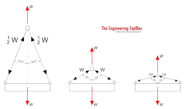
As an example, a horizontal sling angle of 30º will increase the tension factor by 2 times therefore doubling the weight felt by the sling and all related rigging. You can use the chart below to calculate tension factors. If appropriate overhead clearance is available, most riggers use a 60º equilateral triangle as a benchmark angle. A 60º equilateral triangle has three equal sides making it a quick and easy reference point for estimating your sling angle. If a more critical assessment of the sling angle is necessary, the information below can assist in more precise angle calculations. Calculations should always be verified by a qualified person.
In stricter senses, the term wire rope refers to a diameter larger than 9.5 mm (3⁄8 in), with smaller gauges designated cable or cords.wrought iron wires were used, but today steel is the main material used for wire ropes.
Historically, wire rope evolved from wrought iron chains, which had a record of mechanical failure. While flaws in chain links or solid steel bars can lead to catastrophic failure, flaws in the wires making up a steel cable are less critical as the other wires easily take up the load. While friction between the individual wires and strands causes wear over the life of the rope, it also helps to compensate for minor failures in the short run.
Wire ropes were developed starting with mining hoist applications in the 1830s. Wire ropes are used dynamically for lifting and hoisting in cranes and elevators, and for transmission of mechanical power. Wire rope is also used to transmit force in mechanisms, such as a Bowden cable or the control surfaces of an airplane connected to levers and pedals in the cockpit. Only aircraft cables have WSC (wire strand core). Also, aircraft cables are available in smaller diameters than wire rope. For example, aircraft cables are available in 1.2 mm (3⁄64 in) diameter while most wire ropes begin at a 6.4 mm (1⁄4 in) diameter.suspension bridges or as guy wires to support towers. An aerial tramway relies on wire rope to support and move cargo overhead.
Modern wire rope was invented by the German mining engineer Wilhelm Albert in the years between 1831 and 1834 for use in mining in the Harz Mountains in Clausthal, Lower Saxony, Germany.chains, such as had been used before.
Wilhelm Albert"s first ropes consisted of three strands consisting of four wires each. In 1840, Scotsman Robert Stirling Newall improved the process further.John A. Roebling, starting in 1841suspension bridge building. Roebling introduced a number of innovations in the design, materials and manufacture of wire rope. Ever with an ear to technology developments in mining and railroading, Josiah White and Erskine Hazard, principal ownersLehigh Coal & Navigation Company (LC&N Co.) — as they had with the first blast furnaces in the Lehigh Valley — built a Wire Rope factory in Mauch Chunk,Pennsylvania in 1848, which provided lift cables for the Ashley Planes project, then the back track planes of the Summit Hill & Mauch Chunk Railroad, improving its attractiveness as a premier tourism destination, and vastly improving the throughput of the coal capacity since return of cars dropped from nearly four hours to less than 20 minutes. The decades were witness to a burgeoning increase in deep shaft mining in both Europe and North America as surface mineral deposits were exhausted and miners had to chase layers along inclined layers. The era was early in railroad development and steam engines lacked sufficient tractive effort to climb steep slopes, so incline plane railways were common. This pushed development of cable hoists rapidly in the United States as surface deposits in the Anthracite Coal Region north and south dove deeper every year, and even the rich deposits in the Panther Creek Valley required LC&N Co. to drive their first shafts into lower slopes beginning Lansford and its Schuylkill County twin-town Coaldale.
The German engineering firm of Adolf Bleichert & Co. was founded in 1874 and began to build bicable aerial tramways for mining in the Ruhr Valley. With important patents, and dozens of working systems in Europe, Bleichert dominated the global industry, later licensing its designs and manufacturing techniques to Trenton Iron Works, New Jersey, USA which built systems across America. Adolf Bleichert & Co. went on to build hundreds of aerial tramways around the world: from Alaska to Argentina, Australia and Spitsbergen. The Bleichert company also built hundreds of aerial tramways for both the Imperial German Army and the Wehrmacht.
In the last half of the 19th century, wire rope systems were used as a means of transmitting mechanical powercable cars. Wire rope systems cost one-tenth as much and had lower friction losses than line shafts. Because of these advantages, wire rope systems were used to transmit power for a distance of a few miles or kilometers.
Steel wires for wire ropes are normally made of non-alloy carbon steel with a carbon content of 0.4 to 0.95%. The very high strength of the rope wires enables wire ropes to support large tensile forces and to run over sheaves with relatively small diameters.
In the mostly used parallel lay strands, the lay length of all the wire layers is equal and the wires of any two superimposed layers are parallel, resulting in linear contact. The wire of the outer layer is supported by two wires of the inner layer. These wires are neighbors along the whole length of the strand. Parallel lay strands are made in one operation. The endurance of wire ropes with this kind of strand is always much greater than of those (seldom used) with cross lay strands. Parallel lay strands with two wire layers have the construction Filler, Seale or Warrington.
In principle, spiral ropes are round strands as they have an assembly of layers of wires laid helically over a centre with at least one layer of wires being laid in the opposite direction to that of the outer layer. Spiral ropes can be dimensioned in such a way that they are non-rotating which means that under tension the rope torque is nearly zero. The open spiral rope consists only of round wires. The half-locked coil rope and the full-locked coil rope always have a centre made of round wires. The locked coil ropes have one or more outer layers of profile wires. They have the advantage that their construction prevents the penetration of dirt and water to a greater extent and it also protects them from loss of lubricant. In addition, they have one further very important advantage as the ends of a broken outer wire cannot leave the rope if it has the proper dimensions.
Stranded ropes are an assembly of several strands laid helically in one or more layers around a core. This core can be one of three types. The first is a fiber core, made up of synthetic material or natural fibers like sisal. Synthetic fibers are stronger and more uniform but cannot absorb much lubricant. Natural fibers can absorb up to 15% of their weight in lubricant and so protect the inner wires much better from corrosion than synthetic fibers do. Fiber cores are the most flexible and elastic, but have the downside of getting crushed easily. The second type, wire strand core, is made up of one additional strand of wire, and is typically used for suspension. The third type is independent wire rope core (IWRC), which is the most durable in all types of environments.ordinary lay rope if the lay direction of the wires in the outer strands is in the opposite direction to the lay of the outer strands themselves. If both the wires in the outer strands and the outer strands themselves have the same lay direction, the rope is called a lang lay rope (from Dutch langslag contrary to kruisslag,Regular lay means the individual wires were wrapped around the centers in one direction and the strands were wrapped around the core in the opposite direction.
Multi-strand ropes are all more or less resistant to rotation and have at least two layers of strands laid helically around a centre. The direction of the outer strands is opposite to that of the underlying strand layers. Ropes with three strand layers can be nearly non-rotating. Ropes with two strand layers are mostly only low-rotating.
Stationary ropes, stay ropes (spiral ropes, mostly full-locked) have to carry tensile forces and are therefore mainly loaded by static and fluctuating tensile stresses. Ropes used for suspension are often called cables.
Track ropes (full locked ropes) have to act as rails for the rollers of cabins or other loads in aerial ropeways and cable cranes. In contrast to running ropes, track ropes do not take on the curvature of the rollers. Under the roller force, a so-called free bending radius of the rope occurs. This radius increases (and the bending stresses decrease) with the tensile force and decreases with the roller force.
Wire rope slings (stranded ropes) are used to harness various kinds of goods. These slings are stressed by the tensile forces but first of all by bending stresses when bent over the more or less sharp edges of the goods.
Technical regulations apply to the design of rope drives for cranes, elevators, rope ways and mining installations. Factors that are considered in design include:
Donandt force (yielding tensile force for a given bending diameter ratio D/d) - strict limit. The nominal rope tensile force S must be smaller than the Donandt force SD1.
The wire ropes are stressed by fluctuating forces, by wear, by corrosion and in seldom cases by extreme forces. The rope life is finite and the safety is only ensured by inspection for the detection of wire breaks on a reference rope length, of cross-section loss, as well as other failures so that the wire rope can be replaced before a dangerous situation occurs. Installations should be designed to facilitate the inspection of the wire ropes.
Lifting installations for passenger transportation require that a combination of several methods should be used to prevent a car from plunging downwards. Elevators must have redundant bearing ropes and a safety gear. Ropeways and mine hoistings must be permanently supervised by a responsible manager and the rope must be inspected by a magnetic method capable of detecting inner wire breaks.
The end of a wire rope tends to fray readily, and cannot be easily connected to plant and equipment. There are different ways of securing the ends of wire ropes to prevent fraying. The common and useful type of end fitting for a wire rope is to turn the end back to form a loop. The loose end is then fixed back on the wire rope. Termination efficiencies vary from about 70% for a Flemish eye alone; to nearly 90% for a Flemish eye and splice; to 100% for potted ends and swagings.
When the wire rope is terminated with a loop, there is a risk that it will bend too tightly, especially when the loop is connected to a device that concentrates the load on a relatively small area. A thimble can be installed inside the loop to preserve the natural shape of the loop, and protect the cable from pinching and abrading on the inside of the loop. The use of thimbles in loops is industry best practice. The thimble prevents the load from coming into direct contact with the wires.
A wire rope clip, sometimes called a clamp, is used to fix the loose end of the loop back to the wire rope. It usually consists of a U-bolt, a forged saddle, and two nuts. The two layers of wire rope are placed in the U-bolt. The saddle is then fitted to the bolt over the ropes (the saddle includes two holes to fit to the U-bolt). The nuts secure the arrangement in place. Two or more clips are usually used to terminate a wire rope depending on the diameter. As many as eight may be needed for a 2 in (50.8 mm) diameter rope.
The mnemonic "never saddle a dead horse" means that when installing clips, the saddle portion of the assembly is placed on the load-bearing or "live" side, not on the non-load-bearing or "dead" side of the cable. This is to protect the live or stress-bearing end of the rope against crushing and abuse. The flat bearing seat and extended prongs of the body are designed to protect the rope and are always placed against the live end.
The ends of individual strands of this eye splice used aboard a cargo ship are served with natural fiber cord after splicing to help protect seamens" hands when handling.
An eye splice may be used to terminate the loose end of a wire rope when forming a loop. The strands of the end of a wire rope are unwound a certain distance, then bent around so that the end of the unwrapped length forms an eye. The unwrapped strands are then plaited back into the wire rope, forming the loop, or an eye, called an eye splice.
A Flemish eye, or Dutch Splice, involves unwrapping three strands (the strands need to be next to each other, not alternates) of the wire and keeping them off to one side. The remaining strands are bent around, until the end of the wire meets the "V" where the unwrapping finished, to form the eye. The strands kept to one side are now re-wrapped by wrapping from the end of the wire back to the "V" of the eye. These strands are effectively rewrapped along the wire in the opposite direction to their original lay. When this type of rope splice is used specifically on wire rope, it is called a "Molly Hogan", and, by some, a "Dutch" eye instead of a "Flemish" eye.
Swaging is a method of wire rope termination that refers to the installation technique. The purpose of swaging wire rope fittings is to connect two wire rope ends together, or to otherwise terminate one end of wire rope to something else. A mechanical or hydraulic swager is used to compress and deform the fitting, creating a permanent connection. Threaded studs, ferrules, sockets, and sleeves are examples of different swaged terminations.
A wedge socket termination is useful when the fitting needs to be replaced frequently. For example, if the end of a wire rope is in a high-wear region, the rope may be periodically trimmed, requiring the termination hardware to be removed and reapplied. An example of this is on the ends of the drag ropes on a dragline. The end loop of the wire rope enters a tapered opening in the socket, wrapped around a separate component called the wedge. The arrangement is knocked in place, and load gradually eased onto the rope. As the load increases on the wire rope, the wedge become more secure, gripping the rope tighter.
Poured sockets are used to make a high strength, permanent termination; they are created by inserting the wire rope into the narrow end of a conical cavity which is oriented in-line with the intended direction of strain. The individual wires are splayed out inside the cone or "capel", and the cone is then filled with molten lead-antimony-tin (Pb80Sb15Sn5) solder or "white metal capping",zincpolyester resin compound.
Koetsier,Teun; Ceccarelli, Marc (2012). Explorations in the History of Machines and Mechanisms. Springer Publishing. p. 388. ISBN 9789400741324. Archived from the original on 31 March 2017. Retrieved 9 April 2014.
Donald Sayenga. "Modern History of Wire Rope". History of the Atlantic Cable & Submarine Telegraphy (atlantic-cable.com). Archived from the original on 3 February 2014. Retrieved 9 April 2014.


 8613371530291