
when to replace wire rope on crane free sample
Your crane"s wire rope works hard. (Almost as hard as you do.) It can deteriorate more quickly than you might think, posing a real danger for you and your crew. In this article, we"ll answer the following questions.
Before we get into that, let"s take a brief moment to go over the proper wire terminology. Understanding the make-up of the wire rope allows you to have a clear understanding of when the rope needs to be replaced.
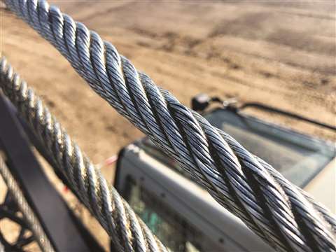
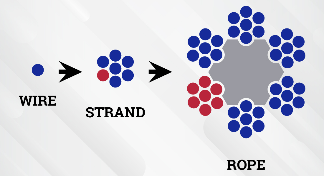
Flexible steel wire rope is made up of individual wires that make up a strand; these strands are then wrapped around a central core to make up a rope.
Understanding the difference between a wire and a strand is critical. If a strand (grouping of wires) in the rope breaks, the crane wire would need to be replaced. However, if a single wire in the strand breaks, the rope itself may still be usable.
Rag & Visual Inspections: In this method, you use a rag in your inspection, pulling it slowly across the strand, stopping for a closer and more detailed inspection wherever the rag gets caught on a wire.
The Diameter Measurement Method: This method involves comparing the diameter of your rope at various intervals with the rope"s official diameter per the manufacturer"s guidelines. A variation in the rope"s diameter can alert you to potential interior damage that a visual inspection would miss.
Localized Flaw Inspections (LF) vs. Loss of Metallic Area Inspections (LMA) - Both methods use electromagnetics to search for a wire rope"s internal damage.
According to OSHA"s safety regulations, you"re required to inspect your crane"s wire ropes at least every 12 months by qualified professionals. However, OSHA and other experts also recommend inspecting your wire ropes more frequently, such as after every initial installation or repair, or daily before each shift to ensure a safe work environment.
As discussed at the very beginning of this article, we can break down wire rope into three parts. First, wires, which make up strands, and then the strands wrapped around the central core make the rope. Of your total number of wires, you never want more than 10% to be damaged before you need to look into crane wire rope replacement.
According to OSHA, only "trained personnel should carry out inspections," and according to the Crane Manufacturers Association of America, a certified crane inspector should get 2,000+ hours of field experience and training.
We at Americrane & Hoist Corporation are just the experts you need, qualified to offer OSHA inspections and provide operator safety training classes to your employees. Contact us today!

A competent person must begin a visual inspection prior to each shift the equipment is used, which must be completed before or during that shift. The inspection must consist of observation of wire ropes (running and standing) that are likely to be in use during the shift for apparent deficiencies, including those listed in paragraph (a)(2) of this section. Untwisting (opening) of wire rope or booming down is not required as part of this inspection.
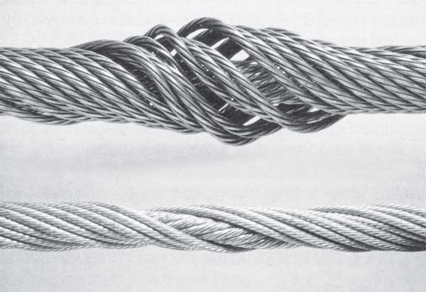
Significant distortion of the wire rope structure such as kinking, crushing, unstranding, birdcaging, signs of core failure or steel core protrusion between the outer strands.
In running wire ropes: Six randomly distributed broken wires in one rope lay or three broken wires in one strand in one rope lay, where a rope lay is the length along the rope in which one strand makes a complete revolution around the rope.
In rotation resistant ropes: Two randomly distributed broken wires in six rope diameters or four randomly distributed broken wires in 30 rope diameters.
In pendants or standing wire ropes: More than two broken wires in one rope lay located in rope beyond end connections and/or more than one broken wire in a rope lay located at an end connection.
If a deficiency in Category I (see paragraph (a)(2)(i) of this section) is identified, an immediate determination must be made by the competent person as to whether the deficiency constitutes a safety hazard. If the deficiency is determined to constitute a safety hazard, operations involving use of the wire rope in question must be prohibited until:
If the deficiency is localized, the problem is corrected by severing the wire rope in two; the undamaged portion may continue to be used. Joining lengths of wire rope by splicing is prohibited. If a rope is shortened under this paragraph, the employer must ensure that the drum will still have two wraps of wire when the load and/or boom is in its lowest position.
If a deficiency in Category II (see paragraph (a)(2)(ii) of this section) is identified, operations involving use of the wire rope in question must be prohibited until:
The employer complies with the wire rope manufacturer"s established criterion for removal from service or a different criterion that the wire rope manufacturer has approved in writing for that specific wire rope (see § 1926.1417),
If the deficiency is localized, the problem is corrected by severing the wire rope in two; the undamaged portion may continue to be used. Joining lengths of wire rope by splicing is prohibited. If a rope is shortened under this paragraph, the employer must ensure that the drum will still have two wraps of wire when the load and/or boom is in its lowest position.
If the deficiency (other than power line contact) is localized, the problem is corrected by severing the wire rope in two; the undamaged portion may continue to be used. Joining lengths of wire rope by splicing is prohibited. Repair of wire rope that contacted an energized power line is also prohibited. If a rope is shortened under this paragraph, the employer must ensure that the drum will still have two wraps of wire when the load and/or boom is in its lowest position.
Where a wire rope is required to be removed from service under this section, either the equipment (as a whole) or the hoist with that wire rope must be tagged-out, in accordance with § 1926.1417(f)(1), until the wire rope is repaired or replaced.
The inspection must include any deficiencies that the qualified person who conducts the annual inspection determines under paragraph (c)(3)(ii) of this section must be monitored.
Wire ropes on equipment must not be used until an inspection under this paragraph demonstrates that no corrective action under paragraph (a)(4) of this section is required.
At least every 12 months, wire ropes in use on equipment must be inspected by a qualified person in accordance with paragraph (a) of this section (shift inspection).
The inspection must be complete and thorough, covering the surface of the entire length of the wire ropes, with particular attention given to all of the following:
Exception: In the event an inspection under paragraph (c)(2) of this section is not feasible due to existing set-up and configuration of the equipment (such as where an assist crane is needed) or due to site conditions (such as a dense urban setting), such inspections must be conducted as soon as it becomes feasible, but no longer than an additional 6 months for running ropes and, for standing ropes, at the time of disassembly.
If a deficiency is identified, an immediate determination must be made by the qualified person as to whether the deficiency constitutes a safety hazard.
If the deficiency is localized, the problem is corrected by severing the wire rope in two; the undamaged portion may continue to be used. Joining lengths of wire rope by splicing is prohibited. If a rope is shortened under this paragraph, the employer must ensure that the drum will still have two wraps of wire when the load and/or boom is in its lowest position.
If the qualified person determines that, though not presently a safety hazard, the deficiency needs to be monitored, the employer must ensure that the deficiency is checked in the monthly inspections.
All documents produced under this section must be available, during the applicable document retention period, to all persons who conduct inspections under this section.
Easy-to-read, question-and-answer fact sheets covering a wide range of workplace health and safety topics, from hazards to diseases to ergonomics to workplace promotion. MORE ABOUT >
Maintain a record for each rope that includes the date of inspection, type of inspection, the name of the person who performed the inspection, and inspection results.
Use the "rag-and-visual" method to check for external damage. Grab the rope lightly and with a rag or cotton cloth, move the rag slowly along the wire. Broken wires will often "porcupine" (stick out) and these broken wires will snag on the rag. If the cloth catches, stop and visually assess the rope. It is also important to visually inspect the wire (without a rag). Some wire breaks will not porcupine.
Measure the rope diameter. Compare the rope diameter measurements with the original diameter. If the measurements are different, this change indicates external and/or internal rope damage.
Visually check for abrasions, corrosion, pitting, and lubrication inside the rope. Insert a marlin spike beneath two strands and rotate to lift strands and open rope.
Assess the condition of the rope at the section showing the most wear. Discard a wire rope if you find any of the following conditions:In running ropes (wound on drums or passed over sheaves), 6 or more broken wires in one rope lay length; 3 or more broken wires in one strand in one rope lay. (One rope lay is the distance necessary to complete one turn of the strand around the diameter of the rope.)
Corrosion from lack of lubrication and exposure to heat or moisture (e.g., wire rope shows signs of pitting). A fibre core rope will dry out and break at temperatures above 120°C (250°F).
Kinks from the improper installation of new rope, the sudden release of a load or knots made to shorten a rope. A kink cannot be removed without creating a weak section. Discarding kinked rope is best.
Although every effort is made to ensure the accuracy, currency and completeness of the information, CCOHS does not guarantee, warrant, represent or undertake that the information provided is correct, accurate or current. CCOHS is not liable for any loss, claim, or demand arising directly or indirectly from any use or reliance upon the information.

Installing wire rope on the drum: If a reel stand is used, take care that the drum is spooled from the top and that the reel feeds from the top. This avoids causing a reverse bend in the wire. A reverse bend will cause spooling problems and damage the wire rope.
When spooling from a reel, make sure a tension device is used so the reel will not overrun the rope. If using a mallet to align rope as it feeds onto the drum, use one with a plastic or rubber-coated face. Do not strike wire rope with a metal-faced hammer or mallet.
Avoid spooling more wire rope onto a drum than is needed. The last layer must be at least two rope diameters below the drum flange top. Spooling more wire rope than is necessary will increase crushing and may cause the rope to jump the flange.
Prevent kinks in the wire: If a loop forms during unreeling STOP! Pulling on a loop will produce a kink that will not work itself out. A kink is a permanent defect and will cause increased wear on the drum, sheaves and the wire rope itself. If kinks must be cut out of the rope, make sure enough rope remains on the drum to provide 2 or 3 wraps (manufacture’s recommendation) on the drum when the crane is extended full range.
Keep the wire rope lubricated: Rust and dirt can deteriorate and weaken a wire rope. In addition, rust and dirt act as an abrasive on the rope as it spools through the sheaves and drums. Lubrication of the rope allows individual wires to move and work together so that all the wires carry the load instead of just a few. Weather and other exposures can also remove the lubricant and allow rust to form.
When inspecting wire rope, first clean the rope using a wire brush, solvent or steam cleaner. Next, inspect the entire rope for damage in accordance with OSHA 1926.550. Once the rope has passed inspection, lubricate it well. Good lubricants are thin enough to penetrate all the way to the core but thick enough to coat each wire individually.
The best method for assuring proper cleaning and lubrication is to use a manufactured lubrication system. These systems work in the following steps: (1) all corrosion and rust is removed; (2) pressure forces out all moisture; and (3) a high-pressure pump forces lubricant throughout the entire rope.
Take rigging for granted and it could be your downfall! Cranes are only as reliable as each of their rigging components. The capacity of wire rope is based on new or well-maintained rope. Its strength can dramatically decrease if it’s poorly cared for. The rope may look strong, but is it safe? Human life and valuable property may depend upon your answer!

Buying new crane ropes is a detailed and thorough process. While it may be time-consuming, wire rope replacement prioritizes safety for your workers, minimizes downtime on a jobsite, maximizes the lifespan of the crane and avoids the costly and time-consuming process of getting correct rope onsite and respooling your crane.
Sometimes, it can seem like the wire rope buying process is overly complicated. This is done on purpose to avoid as many issues as possible when the new rope is installed. The reason for that is so buyers avoid putting the wrong types of ropes on cranes and unnecessarily increasing the risk of injuries to workers or damage to loads being lifted. The processes are to make sure to prevent that added risk and put the correct rope on the correct machine, per Original Equipment Manufacturer (OEM) specifications.
Wire rope specialists ask these questions to understand your circumstances and what your needs are. With this information, they are better prepared to get the absolute correct rope.
Most of the time, the customer should have access to their crane’s operations manual that will show what rope diameter and length is specified. The customer may have to measure or come up with his own calculations on length. The crane manufacturer is going to make a specific drum for that specific type of wire rope.
The rope has to be specific to the lagging of the drum for that machine, which is why there are multiple variations for each size of wire rope because each kind is specific to the type of crane, and it shouldn’t be substituted. Mazzella will only install the rope that is the correct brand and tolerance on a particular crane.
Ordering the correct crane rope will prevent crane rope damage. The wrong rope could cause damage to the equipment, and at worst, boom failure. On the less severe side, you will have bad performance or it might not work at all. You could have twist and/or spooling issues. That could lead to the crane failing altogether, which creates downtime as you wait for the correct wire rope to be ordered/delivered and installed.
Many crane owners are working for somebody else when they’re doing jobs, so if the rope doesn’t work, they’re paying for work that is not getting done and falling behind schedule.
On the more severe side, you could total your crane and/or irreparably damage the load being lifted if you use the wrong wire rope. In the worst-case scenario, using the incorrect rope could result in severe injury and/or the loss of life.
Sometimes, customers assume that there’s a one-size-fits-all replacement, that if it’s a non-rotating rope, it should work on every application. There’s a lot of misinformation on what will work and what won’t work. With our experience and access to all brands of wire rope, Mazzella guarantees we can get you the right rope for your cranes. If Mazzella isn’t comfortable with the project, we won’t supply the wire rope.
If the wrong wire rope is ordered and delivered, it could be hours or days before the correct rope is on location. Especially with a lot of the larger cranes, manufacturers are shipping model-specific ropes all over the country, and depending on location and money, that could cause delays on your jobsite.
With our large inventory of rope, Mazzella can have a new spool of wire on a truck and out for delivery in a matter of hours. Avoid the pitfalls of ordering the wrong crane rope and you’ll have a new spool of wire rope on its way. Once the order process is done, what can your company do to prepare for delivery and installation?
As much as Mazzella can be prepared on our end, the customer needs to be ready for installation so the process can go as smoothly and safely as possible.
You have to make sure the technicians have the requisite space to perform their duties. The easier it is for the installers to get on-site, get to work and finish their responsibilities, the faster your company can get back up and running.
It is a good idea to give management the proper notice of when the installer will be on-site, have the necessary technicians on-site to help the installer with the rope replacement and make sure the installer/technicians have a clear working space.
There’s a lot of downtime associated with making a mistake in the preparation process, so the more prepared you can be for the install, the better. You don’t want a situation where your crane is inactive because of an oversight or completely avoidable situation.
Also, Mazzella recommends you measure your sheaves with a sheave gauge. A sheave gauge will help you measure the wear of the root, the amount of wear on the groove wall and the diameter of the wire rope.
After ordering the correct rope and having the requisite space and approval for installation, how long will it take to remove and replace the old rope when the technician, assistants and supplies arrive onsite? For some small cranes, the timeframe could be as little as 45 minutes, but for larger cranes, removing the old rope and installing the new one could be a several-hour process.
There’s a lot of factors that go into a successful crane rope installation. The most important thing is the quicker your supplier responds to your order and gets a rope on location, the quicker that rope gets installed properly, saving time and money. Downtime is the key, and it could cost companies tens of thousands of dollars per day if their crane(s) are inoperable.
Once a new crane rope is installed, a break-in period or tension period is recommended to make sure everything is performing correctly, and help you avoid shock-loading the newly installed wire rope. The break-in period is recommended because installation and spooling equipment are not going to put adequate tension on the rope. A break-in period consists of putting a low percentage of the working load limit weight on the rope for several lift cycles, and running the blocks up to the boom length (working height) and back down. For the most specific guidelines on the breaking-in process for your new wire rope, refer to the manufacturer’s recommendations.
If a brand-new wire rope on a crane is not broken in properly before lifting a large load, it potentially could damage the rope and render useless the equipment that was just installed on your machine.
When Mazzella fulfills a crane ropes order, it is not just about the sale and the bottom line. While we’re in the business of selling crane ropes, we’re also in the business of building relationships and trust. We are committed to making sure you get the correct products for the right applications.
Crane rope issues don’t just happen 9-to-5 during the normal work week. They happen Friday nights, holidays, weekends and early mornings. They’re always on the clock, and it is just about being honest with the customer and letting them know, they type of rope that is required. That honesty and trust is of utmost importance for the safety of your workers and the proper maintenance of your cranes.
Mazzella has one of the largest crane ropes inventories in the United States. The company provides wire rope assemblies and manufactures bridge cables, crane cables, steel mill cables and thousands of OEM assemblies in sizes from ¼ to 3-inch diameter and 9 to 52 millimeter diameter, domestic and non-domestic and in stock and ready for same or next-day shipment.
Mazzella Companies can also manufacture assemblies with standard or custom end fittings. Special testing and tolerance requirements are also available when necessary.
EN12385-2 Steel wire ropes – Safety – Definitions, designation and classification provides a detailed explanation of all the terms and abbreviations used when describing a wire rope and its components. Below are a few of the most common abbreviations;
Steel wire ropes are specified in terms of a Nominal Rope Diameter and when produced have a manufacturing diameter tolerance, this tolerance can vary depending upon customer requirements and specifications and is often dictated by the diameter of grooving within sheaves and drums in which the wire rope will be expected to operate. If no diameter tolerance is specified, the general diameter tolerance is, Nominal Diameter +0% to +5% as specified within various International Rope Standards (EN12385-4, API-9A, ISO 2408). However, please note other diameter tolerances may be applied to ‘small’ diameter ropes and ropes used for specific applications/industries e.g. Mining, Aerials, Elevators, etc.
When designing any rope operated equipment, designers should consider the relevant National and/or International Standards which refer to acceptable sheave and drum diameters based upon the application, industry, etc. The diameter of sheaves and drums together with the tension, are normally associated with overall service life of the rope and in ‘simple terms’ the larger the diameter the longer the service life, although consideration should also be given to the anticipated modes of rope deterioration which will also significantly affect the service life. Typically, the diameter of sheaves and drums for crane applications are 16 to 28 times the nominal rope diameter.
Wire ropes are generally subjected to a visual examination and specifically for crane ropes these is an International Standard ISO 4309 “Cranes – Wire ropes – Care and maintenance, inspection and discard” which provides guidance on the inspection of wire ropes and provide the discard criteria. The document also includes information on the Magnetic testing of roper in service / Non-Destructive Examination and how this can assist the competent person in combination with his visual examination, determine the overall condition of the rope. All wire ropes should be inspected on a routine basis by a competent person to ensure that they remain is a good condition whilst in service and removed from service before they become dangerous. However, this standard is used for offering guidance for ropes operating in other systems where no specific discard criteria are given for that application, industry or country in which the rope is operating.
Please note, wire ropes can cause death and/or serious injury if not correctly handles, operated and maintained to good condition and care should always be taken when work with or close to wire ropes.
A new rope can easily be damaged if the pulley wheel groove is too tight, this will in effect pinch the rope probably causing a wave (spiral) deformity in your new rope.
If left unchecked in a steel pulley, parallel, linear fatigue wire breaks will be found where the contact pressures have become too high, due to a pinch affect.
The Lang’s construction, due to the wires running across the axis of the rope is the same direction as the strand, provides a greater length of wire on the exterior surface of the rope and hence since there is an increased surface area there is an increased area of steel to wear away before a broken wire occurs, therefore offering greater wear resistance. Therefore, applications where the rope is operating over larger number of support rollers and/or sheaves, the Lang’s lay rope may be of benefit.
The direction of the wires within the Lang’s lay construction also reduces the level of mechanical damage and rope interference, which takes place between adjacent wraps of rope within the crossover zones during multi-layer spooling of wire rope.
It is important to state that, single layer strand and parallel laid, rope constructions, manufactured in Lang’s lay, MUST NOT be used with one end free to rotate. Since the wires and the strands as twisted in the same direction, if the rope is free to rotate the wires and the strands will untwist tighter and seriously affect the integrity and breaking strength of the rope.
Wire ropes may be considered as machines, each with approximately 200 to 300 individual wires, which move independently to each over whenever ropes operate around sheaves or spool on or off winch drums, therefore ensuring ropes are lubricated internally will minimise the level of friction between the individual wires and optimise the ropes bend fatigue performance. Lubricant internally and externally will protect the ropes from corrosion and this applies equally to both un-galvanised/bright ropes and galvanised rope. Although the zinc on the surface of the individual wires of a galvanised rope will protect the wires from corrosion, once the zinc has sacrificed itself (oxidised) to protect the steel, the wires are then susceptible to corrosion. The longer the zinc can be protected by the lubricant the longer the zinc remains to offer protection to the steel. However there are applications where internal or external lubricant on the rope may not be advisable, anywhere the lubricant could drop off the rope and contaminate products (paper, food, etc.) in the vicinity of the rope or where the lubricant on the exterior of the rope may be contaminated with debris in the atmosphere (grit, sand, etc.). In this application, it must be accepted that ‘dry’ ropes will have a significantly reduced service life.
Ropes may be lubricated in-service with either oil or grease, both products offering slightly different benefits. Oils may be applied from a portable spray unit and although the ropes may require being re-lubricated more frequently, since it is relatively easy and cleaning to apply, operators are more likely to re-lubricate the ropes in service. The thin oil may penetrate the rope and surface coat the exterior of the rope with a thin film of lubricant, which also allows for relatively easy routine visual inspection of the rope. Alternatively, rope may be lubricated with a soft bearing type grease; the grease may be applied using a suitable pressure greasing system (Masto, Viper, etc.) to ensure uniform coating of grease along the total length of the rope passing through the greasing system, although the level and colour of grease may make visual inspection difficult. It is important that any oil or grease used to lubricate ropes in service is compatible with the lubricant applied to the rope during manufacturing and Bridon-Bekaert offer a range of wire rope lubricants specially formulated to be suitable for most environments and operations, including ECO VGP 2013 compliant (Bio-degradable, Non-toxic & Non-accumulative) products.
For ropes operating above ambient temperature consideration must be given to the effects the operating temperature may have on the wire rope. For guidance, unless otherwise stated, the maximum operating temperatures are provided in the International Standards e.g. EN 12385-3. However searches of these standards by Bridon-Bekaert indicate that the quoted temperatures within the standards have remained constant for a significant period of time, having been developed when rope constructions and usage centred around common 6-stranded rope constructions. With the introduction of more complex rope constructions incorporating higher tensile grade wires, synthetic lubricants and polymers, Bridon-Bekaert’s experiences indicate that reconsideration of the maximum operating temperatures is required. For high performance ropes incorporating synthetic lubricants and polymers Bridon-Bekaert recommend a maximum operating temperature of 100 degrees C. Excessive bleed out of lubricant from the rope may occur depending upon the rope operating temperature and the type/composition of the lubricant and frequent re-lubrication may be required.
Certain applications (Heave compensation systems, etc.) can generate high operating temperatures and for these and any application or where ropes are stored above ambient temperature, Bridon-Bekaert would be please to discuss this subject further.
Also due the smoothness of the circumference of these rope designs, they reduce wear at the cross over contact points as the rope wraps over itself as it is wound onto the drum.
An Ordinary lay rope is where the individual wires in the outer strands are spun / twisted together in the opposite direction to the direction the outer strands are twisted around the core, which results in the individual wires running along the axis of the rope. A Lang’s lay rope is where the individual wires in the outer stands are twisted in the same direction as the outer strands are twisted around the core, which results in the individual wires running across the rope in the same direction as the strands.
It is important to state that a left hand lay rope and a right hand lay rope MUST never be joined together unless the jointing mechanism is prevented from rotating, otherwise the rope will be allowed to un-twist together, which may have a significant effect on the integrity of the ropes, and could result in failure of the rope. There are two particular situations/arrangements where a left hand and/or right hand rope combination may be considered beneficial;
To prevent rotation of load – Twin rope operating systems (Overhead hoists, Grabbing systems, Container handling cranes, etc.) are generally designed to utilise one left hand rope and one right hand lay rope. When lifting a load both ropes will be subjected to an axial load and will try to un-twist, but since the ropes have been spun in different directions during manufacture one rope will trying to un-twist in one direction whilst the other rope will try to un-twist in the opposite direction, the two ropes therefore acting against each other to prevent/minimise rotation of the load.
When spooling a rope – Tension is generally applied to ropes whilst they are being spooled on to a winch drum and this tension will try to rotate / untwist the rope and therefore it is preferable to have the rope rotating up against the previous wrap of rope to minimise ‘gapping’ between the adjacent wrap of rope particularly on the bottom layer. Therefore, to achieve this, depending if the rope is anchored on the left or right hand side of the drum or the rope is being spooled under-wound or over-wound will determine if, a left or right hand lay rope should be utilised.
Rotation Resistant ropes are normally used to lift or suspend a load without the load rotating (example, hoist ropes used on Offshore, Mobile and Tower cranes, etc.) and are constructed by spinning the inner part of the rope in one direction and the outer part of the rope in the opposite direction. When an axial load is then applied to the rope the inner part will try to untwist in one direction and the outer part will try to untwist in the opposite direction, with the two parts of the rope reacting against each other. Rotation Resistant ropes are normally of a multi-strand construction and constructed of 2-layers of strands with the inner layer spun in the opposite direction to the outer layer and of 3-layers of strands with the inner two layers spun in the opposite direction to the outer layer. Three and four stranded rope constructions may also be considered as rotation resistant, but having only three or four strands, the ropes do not exhibit such a smooth exterior profile and may prove to be more difficult to spool, particularly when multi-layer spooled.
Wire rope does not have a defined shelf-live, provided the rope has been stored and maintained to ensure that the rope has not been allowed to deteriorate. To ensure that ropes remain in good condition, it is considered good practice to ensure the ropes are stored off the ground in a well-ventilated environment, protected from the sun, rain, sand/grit/dirt, chemicals or any other forms of contamination. Depending upon the environment the lubricant on the rope will tend to migrate to the bottom of the reel and dry out during storage. It is therefore good practice to rotate reels to prevent the lubricant migrating out of the rope on to the floor and to re-lubricate the ropes during storage by simple spraying a thin oil on to the surface of the rope to prevent the steel wires from corroding and/or zinc coating on the wires from oxidising (white rust). Whilst wire ropes are in storage they should be routinely inspected to ensure they have not been accidentally damaged, that all identification and certification remains in place and that the ropes remain fit for use. Rope being taken from storage on a ‘first in – first out’ basis, to minimise the length of time in storage.

Wire ropes are essential for safety purposes on construction sites and industrial workplaces. They are used to secure and transport extremely heavy pieces of equipment – so they must be strong enough to withstand substantial loads. This is why the wire rope safety factor is crucial.
You may have heard that it is always recommended to use wire ropes or slings with a higher breaking strength than the actual load. For instance, say that you need to move 50,000 lbs. with an overhead crane. You should generally use equipment with a working load limit that is rated for weight at least five times higher – or 250,000 lbs. in this case.
This recommendation is all thanks to the wire rope safety factor. This calculation is designed to help you determine important numbers, such as the minimum breaking strength and the working load limit of a wire rope.
The safety factor is a measurement of how strong of a force a wire rope can withstand before it breaks. It is commonly stated as a ratio, such as 5:1. This means that the wire rope can hold five times their Safe Work Load (SWL) before it will break.
So, if a 5:1 wire rope’s SWL is 10,000 lbs., the safety factor is 50,000 lbs. However, you would never want to place a load near 50,000 lbs. for wire rope safety reasons.
The safety factor rating of a wire rope is the calculation of the Minimum Break Strength (MBS) or the Minimum Breaking Load (MBL) compared to the highest absolute maximum load limit. It is crucial to use a wire rope with a high ratio to account for factors that could influence the weight of the load.
The Safe Working Load (SWL) is a measurement that is required by law to be clearly marked on all lifting devices – including hoists, lifting machines, and tackles. However, this is not visibly listed on wire ropes, so it is important to understand what this term means and how to calculate it.
The safe working load will change depending on the diameter of the wire rope and its weight per foot. Of course, the smaller the wire rope is, the lower its SWL will be. The SWL also changes depending on the safety factor ratio.
The margin of safety for wire ropes accounts for any unexpected extra loads to ensure the utmost safety for everyone involved. Every year there aredue to overhead crane accidents. Many of these deaths occur when a heavy load is dropped because the weight load limit was not properly calculated and the wire rope broke or slipped.
The margin of safety is a hazard control calculation that essentially accounts for worst-case scenarios. For instance, what if a strong gust of wind were to blow while a crane was lifting a load? Or what if the brakes slipped and the load dropped several feet unexpectedly? This is certainly a wire rope safety factor that must be considered.
Themargin of safety(also referred to as the factor of safety) measures the ultimate load or stress divided by theallowablestress. This helps to account for the applied tensile forces and stress thatcouldbe applied to the rope, causing it to inch closer to the breaking strength limit.
A proof test must be conducted on a wire rope or any other piece of rigging equipment before it is used for the first time.that a sample of a wire rope must be tested to ensure that it can safely hold one-fifth of the breaking load limit. The proof test ensures that the wire rope is not defective and can withstand the minimum weight load limit.
First, the wire rope and other lifting accessories (such as hooks or slings) are set up as needed for the particular task. Then weight or force is slowly added until it reaches the maximum allowable working load limit.
Some wire rope distributors will conduct proof loading tests before you purchase them. Be sure to investigate the criteria of these tests before purchasing, as some testing factors may need to be changed depending on your requirements.
When purchasing wire ropes for overhead lifting or other heavy-duty applications, understanding the safety dynamics and limits is critical. These terms can get confusing, but all of thesefactors serve an important purpose.
Our company has served as a wire rope distributor and industrial hardware supplier for many years. We know all there is to know about safety factors. We will help you find the exact wire ropes that will meet your requirements, no matter what project you have in mind.
In stricter senses, the term wire rope refers to a diameter larger than 9.5 mm (3⁄8 in), with smaller gauges designated cable or cords.wrought iron wires were used, but today steel is the main material used for wire ropes.
Historically, wire rope evolved from wrought iron chains, which had a record of mechanical failure. While flaws in chain links or solid steel bars can lead to catastrophic failure, flaws in the wires making up a steel cable are less critical as the other wires easily take up the load. While friction between the individual wires and strands causes wear over the life of the rope, it also helps to compensate for minor failures in the short run.
Wire ropes were developed starting with mining hoist applications in the 1830s. Wire ropes are used dynamically for lifting and hoisting in cranes and elevators, and for transmission of mechanical power. Wire rope is also used to transmit force in mechanisms, such as a Bowden cable or the control surfaces of an airplane connected to levers and pedals in the cockpit. Only aircraft cables have WSC (wire strand core). Also, aircraft cables are available in smaller diameters than wire rope. For example, aircraft cables are available in 1.2 mm (3⁄64 in) diameter while most wire ropes begin at a 6.4 mm (1⁄4 in) diameter.suspension bridges or as guy wires to support towers. An aerial tramway relies on wire rope to support and move cargo overhead.
Modern wire rope was invented by the German mining engineer Wilhelm Albert in the years between 1831 and 1834 for use in mining in the Harz Mountains in Clausthal, Lower Saxony, Germany.chains, such as had been used before.
Wilhelm Albert"s first ropes consisted of three strands consisting of four wires each. In 1840, Scotsman Robert Stirling Newall improved the process further.John A. Roebling, starting in 1841suspension bridge building. Roebling introduced a number of innovations in the design, materials and manufacture of wire rope. Ever with an ear to technology developments in mining and railroading, Josiah White and Erskine Hazard, principal ownersLehigh Coal & Navigation Company (LC&N Co.) — as they had with the first blast furnaces in the Lehigh Valley — built a Wire Rope factory in Mauch Chunk,Pennsylvania in 1848, which provided lift cables for the Ashley Planes project, then the back track planes of the Summit Hill & Mauch Chunk Railroad, improving its attractiveness as a premier tourism destination, and vastly improving the throughput of the coal capacity since return of cars dropped from nearly four hours to less than 20 minutes. The decades were witness to a burgeoning increase in deep shaft mining in both Europe and North America as surface mineral deposits were exhausted and miners had to chase layers along inclined layers. The era was early in railroad development and steam engines lacked sufficient tractive effort to climb steep slopes, so incline plane railways were common. This pushed development of cable hoists rapidly in the United States as surface deposits in the Anthracite Coal Region north and south dove deeper every year, and even the rich deposits in the Panther Creek Valley required LC&N Co. to drive their first shafts into lower slopes beginning Lansford and its Schuylkill County twin-town Coaldale.
The German engineering firm of Adolf Bleichert & Co. was founded in 1874 and began to build bicable aerial tramways for mining in the Ruhr Valley. With important patents, and dozens of working systems in Europe, Bleichert dominated the global industry, later licensing its designs and manufacturing techniques to Trenton Iron Works, New Jersey, USA which built systems across America. Adolf Bleichert & Co. went on to build hundreds of aerial tramways around the world: from Alaska to Argentina, Australia and Spitsbergen. The Bleichert company also built hundreds of aerial tramways for both the Imperial German Army and the Wehrmacht.
In the last half of the 19th century, wire rope systems were used as a means of transmitting mechanical powercable cars. Wire rope systems cost one-tenth as much and had lower friction losses than line shafts. Because of these advantages, wire rope systems were used to transmit power for a distance of a few miles or kilometers.
Steel wires for wire ropes are normally made of non-alloy carbon steel with a carbon content of 0.4 to 0.95%. The very high strength of the rope wires enables wire ropes to support large tensile forces and to run over sheaves with relatively small diameters.
In the mostly used parallel lay strands, the lay length of all the wire layers is equal and the wires of any two superimposed layers are parallel, resulting in linear contact. The wire of the outer layer is supported by two wires of the inner layer. These wires are neighbors along the whole length of the strand. Parallel lay strands are made in one operation. The endurance of wire ropes with this kind of strand is always much greater than of those (seldom used) with cross lay strands. Parallel lay strands with two wire layers have the construction Filler, Seale or Warrington.
In principle, spiral ropes are round strands as they have an assembly of layers of wires laid helically over a centre with at least one layer of wires being laid in the opposite direction to that of the outer layer. Spiral ropes can be dimensioned in such a way that they are non-rotating which means that under tension the rope torque is nearly zero. The open spiral rope consists only of round wires. The half-locked coil rope and the full-locked coil rope always have a centre made of round wires. The locked coil ropes have one or more outer layers of profile wires. They have the advantage that their construction prevents the penetration of dirt and water to a greater extent and it also protects them from loss of lubricant. In addition, they have one further very important advantage as the ends of a broken outer wire cannot leave the rope if it has the proper dimensions.
Stranded ropes are an assembly of several strands laid helically in one or more layers around a core. This core can be one of three types. The first is a fiber core, made up of synthetic material or natural fibers like sisal. Synthetic fibers are stronger and more uniform but cannot absorb much lubricant. Natural fibers can absorb up to 15% of their weight in lubricant and so protect the inner wires much better from corrosion than synthetic fibers do. Fiber cores are the most flexible and elastic, but have the downside of getting crushed easily. The second type, wire strand core, is made up of one additional strand of wire, and is typically used for suspension. The third type is independent wire rope core (IWRC), which is the most durable in all types of environments.ordinary lay rope if the lay direction of the wires in the outer strands is in the opposite direction to the lay of the outer strands themselves. If both the wires in the outer strands and the outer strands themselves have the same lay direction, the rope is called a lang lay rope (from Dutch langslag contrary to kruisslag,Regular lay means the individual wires were wrapped around the centers in one direction and the strands were wrapped around the core in the opposite direction.
Multi-strand ropes are all more or less resistant to rotation and have at least two layers of strands laid helically around a centre. The direction of the outer strands is opposite to that of the underlying strand layers. Ropes with three strand layers can be nearly non-rotating. Ropes with two strand layers are mostly only low-rotating.
Stationary ropes, stay ropes (spiral ropes, mostly full-locked) have to carry tensile forces and are therefore mainly loaded by static and fluctuating tensile stresses. Ropes used for suspension are often called cables.
Track ropes (full locked ropes) have to act as rails for the rollers of cabins or other loads in aerial ropeways and cable cranes. In contrast to running ropes, track ropes do not take on the curvature of the rollers. Under the roller force, a so-called free bending radius of the rope occurs. This radius increases (and the bending stresses decrease) with the tensile force and decreases with the roller force.
Wire rope slings (stranded ropes) are used to harness various kinds of goods. These slings are stressed by the tensile forces but first of all by bending stresses when bent over the more or less sharp edges of the goods.
Technical regulations apply to the design of rope drives for cranes, elevators, rope ways and mining installations. Factors that are considered in design include:
Donandt force (yielding tensile force for a given bending diameter ratio D/d) - strict limit. The nominal rope tensile force S must be smaller than the Donandt force SD1.
The wire ropes are stressed by fluctuating forces, by wear, by corrosion and in seldom cases by extreme forces. The rope life is finite and the safety is only ensured by inspection for the detection of wire breaks on a reference rope length, of cross-section loss, as well as other failures so that the wire rope can be replaced before a dangerous situation occurs. Installations should be designed to facilitate the inspection of the wire ropes.
Lifting installations for passenger transportation require that a combination of several methods should be used to prevent a car from plunging downwards. Elevators must have redundant bearing ropes and a safety gear. Ropeways and mine hoistings must be permanently supervised by a responsible manager and the rope must be inspected by a magnetic method capable of detecting inner wire breaks.
The end of a wire rope tends to fray readily, and cannot be easily connected to plant and equipment. There are different ways of securing the ends of wire ropes to prevent fraying. The common and useful type of end fitting for a wire rope is to turn the end back to form a loop. The loose end is then fixed back on the wire rope. Termination efficiencies vary from about 70% for a Flemish eye alone; to nearly 90% for a Flemish eye and splice; to 100% for potted ends and swagings.
When the wire rope is terminated with a loop, there is a risk that it will bend too tightly, especially when the loop is connected to a device that concentrates the load on a relatively small area. A thimble can be installed inside the loop to preserve the natural shape of the loop, and protect the cable from pinching and abrading on the inside of the loop. The use of thimbles in loops is industry best practice. The thimble prevents the load from coming into direct contact with the wires.
A wire rope clip, sometimes called a clamp, is used to fix the loose end of the loop back to the wire rope. It usually consists of a U-bolt, a forged saddle, and two nuts. The two layers of wire rope are placed in the U-bolt. The saddle is then fitted to the bolt over the ropes (the saddle includes two holes to fit to the U-bolt). The nuts secure the arrangement in place. Two or more clips are usually used to terminate a wire rope depending on the diameter. As many as eight may be needed for a 2 in (50.8 mm) diameter rope.
The mnemonic "never saddle a dead horse" means that when installing clips, the saddle portion of the assembly is placed on the load-bearing or "live" side, not on the non-load-bearing or "dead" side of the cable. This is to protect the live or stress-bearing end of the rope against crushing and abuse. The flat bearing seat and extended prongs of the body are designed to protect the rope and are always placed against the live end.
The ends of individual strands of this eye splice used aboard a cargo ship are served with natural fiber cord after splicing to help protect seamens" hands when handling.
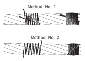
An eye splice may be used to terminate the loose end of a wire rope when forming a loop. The strands of the end of a wire rope are unwound a certain distance, then bent around so that the end of the unwrapped length forms an eye. The unwrapped strands are then plaited back into the wire rope, forming the loop, or an eye, called an eye splice.
A Flemish eye, or Dutch Splice, involves unwrapping three strands (the strands need to be next to each other, not alternates) of the wire and keeping them off to one side. The remaining strands are bent around, until the end of the wire meets the "V" where the unwrapping finished, to form the eye. The strands kept to one side are now re-wrapped by wrapping from the end of the wire back to the "V" of the eye. These strands are effectively rewrapped along the wire in the opposite direction to their original lay. When this type of rope splice is used specifically on wire rope, it is called a "Molly Hogan", and, by some, a "Dutch" eye instead of a "Flemish" eye.
Swaging is a method of wire rope termination that refers to the installation technique. The purpose of swaging wire rope fittings is to connect two wire rope ends together, or to otherwise terminate one end of wire rope to something else. A mechanical or hydraulic swager is used to compress and deform the fitting, creating a permanent connection. Threaded studs, ferrules, sockets, and sleeves are examples of different swaged terminations.
A wedge socket termination is useful when the fitting needs to be replaced frequently. For example, if the end of a wire rope is in a high-wear region, the rope may be periodically trimmed, requiring the termination hardware to be removed and reapplied. An example of this is on the ends of the drag ropes on a dragline. The end loop of the wire rope enters a tapered opening in the socket, wrapped around a separate component called the wedge. The arrangement is knocked in place, and load gradually eased onto the rope. As the load increases on the wire rope, the wedge become more secure, gripping the rope tighter.
Poured sockets are used to make a high strength, permanent termination; they are created by inserting the wire rope into the narrow end of a conical cavity which is oriented in-line with the intended direction of strain. The individual wires are splayed out inside the cone or "capel", and the cone is then filled with molten lead-antimony-tin (Pb80Sb15Sn5) solder or "white metal capping",zincpolyester resin compound.
Koetsier,Teun; Ceccarelli, Marc (2012). Explorations in the History of Machines and Mechanisms. Springer Publishing. p. 388. ISBN 9789400741324. Archived from the original on 31 March 2017. Retrieved 9 April 2014.
Donald Sayenga. "Modern History of Wire Rope". History of the Atlantic Cable & Submarine Telegraphy (atlantic-cable.com). Archived from the original on 3 February 2014. Retrieved 9 April 2014.


 8613371530291