
wire rope 101 factory
You might be surprised to learn that industrial cable has been around for thousands of years. Metal wires are mentioned in ancient textsdating back to 4000 BC, and archeologists have found industrial cables made of bronze used in Pompei!
The construction of industrial cable may have changed a bit over the past few millennia, but many of the properties of these steel wires has remained. Over the years, we have discovered ways to create more sturdy cables by adding iron alloys like Chromium to create stainless steel cables. Cables now also come in a range of sizes, lengths, and diameters to optimize their use for specific applications.
First and foremost, we need toexplain the differencesbetween wire ropes and industrial cable. While both of these pieces of hardware share many similar properties, they should not be used interchangeably. Yes, industrial cables are made of wires, but they are not the same as wire ropes.
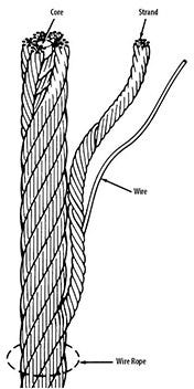
Wire ropes are constructed from wires that are woven together similarly to a fabricated rope. This creates a flexible but strong material that can be used to add support to an object. This is why wire ropes are primarily used for overhead lifting or securement and tie-downs.
Industrial cables on the other hand tend to be much thinner than wire ropes and much more flexible. They can be wrapped around or threaded through hooks and loops to hold items in place and are used for more permanent fixtures.
Just like wire ropes, industrial cables are constructed from strands made of a number of wires wrapped together. The general rule of thumb here is that the more wires in a strand or the more strands in the cable, the more flexible it will be.
Most steel cables are available in either a 7×7 or 7×19 construction. The first number communicates the number of strands used in the cable, while the second demonstrates the number of wires per strand. A 7×7 cable has 7 strands of 7 wires, while a 7×19 is 7 strands made of 19 wires each.
The interior strand of an industrial cable creates a supportive structure for the strands to wrap around. This core may be made of fibers, like hemp or polypropylene, wire strand, or an independent wire rope core (IWRC). Fiber cores are quite flexible, but not very durable and not recommended for heavy-duty applications. Wire ropes or IWRC add strength and crush resistance, making them ideal for construction use.
Another key categorization for cables is the material used to construct the wires. While industrial cables are always made from steel, there are different grades and finishes offered.
This is a ratio that compares the strength of the cable or wire rope to the working load. This helps to create a safety net for additional factors that can place stress on the cable, such as the speed of movement, friction, and types of fittings.
Frequent movement and abrasion on the wires of a cable will eventually damage the cable, compromising its strength. Be sure to consider the load and stress factors placed on the cable, such as load shock, friction, and constant bending.
Bergen Cable knows that different applications for wire rope present varying demands for strength, abrasion and corrosion resistance. To meet these requirements, the Fairfield. N.J.-based company produces wire rope in a number of different materials and styles — each with its own ideal applications.
For applications where corrosion is a concern, stainless steel wire rope is the best option. Type 302 (18 per cent chromium and eight per cent nickel alloy) is the most common grade accepted because of its corrosion resistance and high strength. Other frequently used stainless steel types are 304, 305, 316 and 321, each with its own set of pros and cons. Type 305, for example, is used where non-magnetic properties are required; however, there is a slight loss of strength. Users must determine where their priorities lie in the application, and if the compromise is worth it.
For applications where strength is required and corrosion resistance is not great enough to justify the cost of stainless steel, galvanized carbon steel is an option. Wires used in these wire ropes are individually coated with a layer of zinc, which offers some protection from corrosive elements.
In addition to wire rope material, cable construction is also a consideration. The greater the number of wires the strand or cable has, the more flexible it is. A 1×7 or a 1×19 strand, with seven and 19 wires respectively, is used as a fixed member, straight linkage or where flexing is minimal. The 1×7 offers the least stretch, while the 1×19 is fairly flexible and resists compressive forces.
Bergen Cable has the expertise to help its customers select the most appropriate wire rope for their applications. For more information, contact Bergen Cable.
Wire rope and cable are each considered a “machine”. The configuration and method of manufacture combined with the proper selection of material when designed for a specific purpose enables a wire rope or cable to transmit forces, motion and energy in some predetermined manner and to some desired end.
Two or more wires concentrically laid around a center wire is called a strand. It may consist of one or more layers. Typically, the number of wires in a strand is 7, 19 or 37. A group of strands laid around a core would be called a cable or wire rope. In terms of product designation, 7 strands with 19 wires in each strand would be a 7×19 cable: 7 strands with 7 wires in each strand would be a 7×7 cable.
Materials Different applications for wire rope present varying demands for strength, abrasion and corrosion resistance. In order to meet these requirements, wire rope is produced in a number of different materials.
Stainless Steel This is used where corrosion is a prime factor and the cost increase warrants its use. The 18% chromium, 8% nickel alloy known as type 302 is the most common grade accepted due to both corrosion resistance and high strength. Other types frequently used in wire rope are 304, 305, 316 and 321, each having its specific advantage over the other. Type 305 is used where non-magnetic properties are required, however, there is a slight loss of strength.
Galvanized Carbon Steel This is used where strength is a prime factor and corrosion resistance is not great enough to require the use of stainless steel. The lower cost is usually a consideration in the selection of galvanized carbon steel. Wires used in these wire ropes are individually coated with a layer of zinc which offers a good measure of protection from corrosive elements.
Cable Construction The greater the number of wires in a strand or cable of a given diameter, the more flexibility it has. A 1×7 or a 1×19 strand, having 7 and 19 wires respectively, is used principally as a fixed member, as a straight linkage, or where flexing is minimal.
Selecting Wire Rope When selecting a wire rope to give the best service, there are four requirements which should be given consideration. A proper choice is made by correctly estimating the relative importance of these requirements and selecting a rope which has the qualities best suited to withstand the effects of continued use. The rope should possess:Strength sufficient to take care of the maximum load that may be applied, with a proper safety factor.
Strength Wire rope in service is subjected to several kinds of stresses. The stresses most frequently encountered are direct tension, stress due to acceleration, stress due to sudden or shock loads, stress due to bending, and stress resulting from several forces acting at one time. For the most part, these stresses can be converted into terms of simple tension, and a rope of approximately the correct strength can be chosen. As the strength of a wire rope is determined by its, size, grade and construction, these three factors should be considered.
Safety Factors The safety factor is the ratio of the strength of the rope to the working load. A wire rope with a strength of 10,000 pounds and a total working load of 2,000 pounds would be operating with a safety factor of five.
It is not possible to set safety factors for the various types of wire rope using equipment, as this factor can vary with conditions on individual units of equipment.
The proper safety factor depends not only on the loads applied, but also on the speed of operation, shock load applied, the type of fittings used for securing the rope ends, the acceleration and deceleration, the length of rope, the number, size and location of sheaves and drums, the factors causing abrasion and corrosion and the facilities for inspection.
Fatigue Fatigue failure of the wires in a wire rope is the result of the propagation of small cracks under repeated applications of bending loads. It occurs when ropes operate over comparatively small sheaves or drums. The repeated bending of the individual wires, as the rope bends when passing over the sheaves or drums, and the straightening of the individual wires, as the rope leaves the sheaves or drums, causing fatigue. The effect of fatigue on wires is illustrated by bending a wire repeatedly back and forth until it breaks.
The best means of preventing early fatigue of wire ropes is to use sheaves and drums of adequate size. To increase the resistance to fatigue, a rope of more flexible construction should be used, as increased flexibility is secured through the use of smaller wires.
Abrasive Wear The ability of a wire rope to withstand abrasion is determined by the size, the carbon and manganese content, the heat treatment of the outer wires and the construction of the rope. The larger outer wires of the less flexible constructions are better able to withstand abrasion than the finer outer wires of the more flexible ropes. The higher carbon and manganese content and the heat treatment used in producing wire for the stronger ropes, make the higher grade ropes better able to withstand abrasive wear than the lower grade ropes.
Effects of Bending All wire ropes, except stationary ropes used as guys or supports, are subjected to bending around sheaves or drums. The service obtained from wire ropes is, to a large extent, dependent upon the proper choice and location of the sheaves and drums about which it operates.
A wire rope may be considered a machine in which the individual elements (wires and strands) slide upon each other when the rope is bent. Therefore, as a prerequisite to the satisfactory operation of wire rope over sheaves and drums, the rope must be properly lubricated.
Loss of strength due to bending is caused by the inability of the individual strands and wires to adjust themselves to their changed position when the rope is bent. Tests made by the National Institute of Standards and Technology show that the rope strength decreases in a marked degree as the sheave diameter grows smaller with respect to the diameter of the rope. The loss of strength due to bending wire ropes over the sheaves found in common use will not exceed 6% and will usually be about 4%.
The bending of a wire rope is accompanied by readjustment in the positions of the strands and wires and results in actual bending of the wires. Repetitive flexing of the wires develops bending loads which, even though well within the elastic limit of the wires, set up points of stress concentration.
The fatigue effect of bending appears in the form of small cracks in the wires at these over-stressed foci. These cracks propagate under repeated stress cycles, until the remaining sound metal is inadequate to withstand the bending load. This results in broken wires showing no apparent contraction of cross section.
Experience has established the fact that from the service view-point, a very definite relationship exists between the size of the individual outer wires of a wire rope and the size of the sheave or drum about which it operates. Sheaves and drums smaller than 200 times the diameter of the outer wires will cause permanent set in a heavily loaded rope. Good practice requires the use of sheaves and drums with diameters 800 times the diameter of the outer wires in the rope for heavily loaded fast-moving ropes.
It is impossible to give a definite minimum size of sheave or drum about which a wire rope will operate with satisfactory results, because of the other factors affecting the useful life of the rope. If the loads are light or the speed slow, smaller sheaves and drums can be used without causing early fatigue of the wires than if the loads are heavy or the speed is fast. Reverse bends, where a rope is bent in one direction and then in the opposite direction, cause excessive fatigue and should be avoided whenever possible. When a reverse bend is necessary larger sheaves are required than would be the case if the rope were bent in one direction only.
Stretch of Wire Rope The stretch of a wire rope under load is the result of two components: the structural stretch and the elastic stretch. Structural stretch of wire rope is caused by the lengthening of the rope lay, compression of the core and adjustment of the wires and strands to the load placed upon the wire rope. The elastic stretch is caused by elongation of the wires.
The structural stretch varies with the size of core, the lengths of lays and the construction of the rope. This stretch also varies with the loads imposed and the amount of bending to which the rope is subjected. For estimating this stretch the value of one-half percent, or .005 times the length of the rope under load, gives an approximate figure. If loads are light, one-quarter percent or .0025 times the rope length may be used. With heavy loads, this stretch may approach one percent, or .01 times the rope length.
The elastic stretch of a wire rope is directly proportional to the load and the length of rope under load, and inversely proportional to the metallic area and modulus of elasticity. This applies only to loads that do not exceed the elastic limit of a wire rope. The elastic limit of stainless steel wire rope is approximately 60% of its breaking strength and for galvanized ropes it is approximately 50%.
Preformed Wire Ropes Preformed ropes differ from the standard, or non-preformed ropes, in that the individual wires in the strands and the strands in the rope are preformed, or pre-shaped to their proper shape before they are assembled in the finished rope.
This, in turn, results in preformed wire ropes having the following characteristics:They can be cut without the seizings necessary to retain the rope structure of non-preformed ropes.
They are substantially free from liveliness and twisting tendencies. This makes installation and handling easier, and lessens the likelihood of damage to the rope from kinking or fouling. Preforming permits the more general use of Lang lay and wire core constructions.
Removal of internal stresses increase resistance to fatigue from bending. This results in increased service where ability to withstand bending is the important requirement. It also permits the use of ropes with larger outer wires, when increased wear resistance is desired.
Outer wires will wear thinner before breaking, and broken wire ends will not protrude from the rope to injure worker’s hands, to nick and distort adjacent wires, or to wear sheaves and drums. Because of the fact that broken wire ends do not porcupine, they are not as noticeable as they are in non-preformed ropes. This necessitates the use of greater care when inspecting worn preformed ropes, to determine their true condition.

AIRCRAFT WIRE ROPE 101 WIRE ROPE Cable .......................................................1-18 Abrasion and Bending ..............................1-4 7-Strand...................................................1-16 Block Twisting .......................................1-4–5 Bridge Rope ............................................1-16BRIDGE Calculating Drum Capacity .......................1-8 Cable .................................................1-18–20 Wire Rope ...............................................1-16 Common Abuses.......................................1-5 Corrosion Resistant.................................1-17CABLE Common Causes of Failure ......................1-6 Drag.........................................................1-13 Aircraft .....................................................1-18 Conversion Tables Metric/English .............1-8 Electrical Construction ............................1-14 Alloy.........................................................1-20 Cross Sections (Illustrations) ....................1-2 Elevator ...................................................1-14 Coated.....................................................1-20 Design and Construction...........................1-1 Flattened Strand......................................1-12 Stainless Steel ........................................1-19 Glossary ............................................1-21–22 Galvanized Structural Strand ..................1-16DRAG Inspection ..................................................1-3 Galvanized Wire Strand ..........................1-12 Rope........................................................1-13 Installation .................................................1-7 General Purpose .....................................1-10 Lay of Wire Rope .....................................1-1 Herringbone ............................................1-13DRILLING AND WELL WIRE ROPE.........1-15 High Performance ...................................1-12 Lubrication.................................................1-7ELEVATOR Matching Rope to Sheave and Drum....1-7–8 Logging ...................................................1-15 Wire Rope ...............................................1-14 Matching Sheave Groove to Rope ............1-8 Marine Application...................................1-14 Nominal Strength ......................................1-3 Oil/Gas Drilling ........................................1-15FLATTENED STRAND WIRE ROPE.........1-12 Operating...................................................1-7 Plastic Filled Valley..................................1-17HERRINGBONE Physical Properties ...................................1-6 Rotation Resistant...................................1-11 Wire Rope ...............................................1-13 Rope Strength Design Factors..................1-4 Stainless..................................................1-19LOGGING Selection Guide.........................................1-6 Strand Hoist ............................................1-13 Wire Rope ...............................................1-15 Sheave Inspection.....................................1-3 Surface Mining ........................................1-13 Weights .....................................................1-3 Swage .....................................................1-15METRIC/ENGLISH Tower Power............................................1-11 What Wire Rope Is... .................................1-1 Conversion Tables .....................................1-8 Tramway ..................................................1-14 Wire Grades ..............................................1-1MINING AND EXCAVATION WIRE ROPE 1-13 Underground Mining................................1-14MINING AND TRAMWAY WIRE ROPE .....1-14 Well Service ............................................1-15
ROTATION WIRE ROPE, GENERAL PURPOSE Resistant Wire Rope ...............................1-11 6 x 7 Classification ..................................1-10 6 x 19 Classification ................................1-10STAINLESS 6 x 19 Seale Steel Cable..............................................1-19 6 x 21 Filler WireSTRAND 6 x 25 Filler Wire Hoist Wire Rope ......................................1-13 6 x 26 Warrington Seale 6 x 31 Warrington SealSWAGED 6 x 36 Warrington Seale Wire Rope ...............................................1-15 6 x 37 Classification ................................1-10TOWER CRANE 6 x 41 Seale Filler Wire Wire Rope ...............................................1-11 6 x 41 Warrington Seale 6 x 49 Seale Warrington Seale
WWW.HANESSUPPLY.COM 1- A Buffalo - Headquarters: 716.826.2636 FAX: 716.826.4412 Hanes Supply of SC, Inc. Albany/NE Division: 518.438.0139 FAX: 518.438.5343 CCISCO: 843.238.1338 Rochester Division: 585.235.0160 FAX: 585.235.0229 FAX: 843.238.83371 NOTESWire Rope
1- B WWW.HANESSUPPLY.COM Buffalo - Headquarters: 716.826.2636 FAX: 716.826.4412 Hanes Supply of SC, Inc. Albany/NE Division: 518.438.0139 FAX: 518.438.5343 CCISCO: 843.238.1338 Rochester Division: 585.235.0160 FAX: 585.235.0229 FAX: 843.238.8337 Wire Rope 1 Wire Rope 101
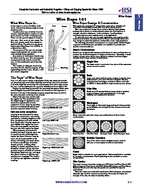
Wire RopeWhat Wire Rope Is... Wire Rope Design & ConstructionA wire rope is a piece of flexible, multi- Core Strand Wire ropes are composed of independent parts–wires, strands and cores-wired, stranded machinery made of many that continuously interact with each other during service.precision parts. Wire rope engineers design those parts in differing steel grades, finish- Usually a wire rope consists of a core es and a variety of constructions to attain the best balance of strength,member, around which a number of multi- abrasion resistance, crush resistance, bending fatigue resistance and cor-wired strands are “laid” or helically bent. rosion resistance for each application. To select the best wire rope for each application, one must know theThere are two general types of cores for required performance characteristics for the job and enough about wirewire rope - fiber cores an wire cores. The rope design to select the optimum combination of wire rope properties.fiber core may be made from natural or The following information is presented as a basic guide. Hanes Supplysynthetic fibers. The wire core can be an engineers and field service specialists are available to provide more spe-Independent Wire Rope Core (IWRC), or cific recommendations.a Strand Core (SC). Wire The purpose of the core is to provide Strand Constructionssupport and maintain the position of the Strands are designed with various combinations of wires and wire sizes toouter strands during operation. produce the desired resistance to fatigue and abrasion. Generally, a small Any number of multi-wired strands may number of large wires will be more abrasion resistant and less fatiguebe laid around the core. The most popular resistant than a large number of small wires.arrangement is six strands around thecore, as this combination gives the best Single Sizebalance. The basic strand construction has wires of the same The number of wires per strand may size wound around a center.vary from 3 to 91, with the majority of wire Wire Roperopes failing into the 7-wire, 19-wire, or37-wire strand categories.
SealeThe “lays” of Wire Rope Large outer wires with the same number of smaller inner wires around a core wire. Provides excellent abrasion“Lay” of a wire rope is simply a description of the way wires and strands resistance but less fatigue resistance. When used withare placed during construction. Right lay and left lay refer to the direction an IWRC, it offers excellent crush resistance over drums.of strands. Right lay means that the strands pass from left to right acrossthe rope. Left lay means just the opposite: strands pass from right to left. Regular lay and lang lay describe the way wires are placed within each Filler Wirestrand. Regular lay means that wires in the strands are laid opposite in Small wires fill spaces between large wires to producedirection to the lay of the strands. Lang lay means that wires are laid in crush resistance and a good balance of strength, flexibil-the same direction as the lay of the strands. ity and resistance to abrasion. Most of the wire rope used is rightlay, regular lay. This specification hasthe widest range of applications andmeets the requirements of most Warringtonequipment. In fact, other lay specifica- Outer layer of alternately large and small wires providestions are considered exceptions and good flexibility and strength but low abrasion and crushmust be requested when ordering. Left Lay REGULAR LAY resistance.Here are some exceptionsLang lay is recommended for many Many commonly used wire ropes use combinations of these basic con-excavating, construction, and mining structions.applications, including draglines, hoistlines, dredgelines and other similar Left Lay LANG LAYlines. Here"s why: Lang lay ropes aremore flexible than regular lay ropes.They also have greater wearing sur-face per wire than regular lay ropes. Where properly recommended,installed and used, lang lay ropes can Right Alternate Lay Seale Filler Wire Filler Wire Seale Warrington Seale Seale Warrington Sealebe used to greater advantage thanregular lay ropes. However, lang layropes are more susceptible to the Multiple Operationabuses of bending over small diame- One of the above strand designs may be covered withter sheaves, pinching in undersize one or more layers of uniform-sized wires.sheave grooves, crushing when wind-ing on drums, and failing due to Right Lay REGULAR LAYexcessive rotation. Left lay rope hasgreatest usage in oil fields on rod andtubing lines, blast hole rigs, and spud- Finishders where rotation of right lay rope Bright finish is suitable for most applications. Galvanized finish is availablewould loosen couplings. The rotation for corrosive environments. Plastic jacketing is also available on someof a left lay rope tightens a standard constructions.coupling. Right Lay LANG LAY Wire Grades The most common steel wire grades are: IPS (Improved Plow Steel), EIP (Extra Improved Plow Steel) and EEIP (Extra Extra Improved Plow Steel). Stainless Steels and other special grades are provided for special appli- cations. Most wire ropes are made with round wires. Both triangular and shaped wires are also used for special constructions. Generally, the higher the strength of the wire, the lower its ductility will be.
WWW.HANESSUPPLY.COM 1- 1 Buffalo - Headquarters: 716.826.2636 FAX: 716.826.4412 Hanes Supply of SC, Inc. Albany/NE Division: 518.438.0139 FAX: 518.438.5343 CCISCO: 843.238.1338 Rochester Division: 585.235.0160 FAX: 585.235.0229 FAX: 843.238.83371 Wire Rope Wire Rope 101Wire Rope
6x7 6 x 12 6 x 17 6 x 19 6 x 21 Poly Core (Marine Rope) Filler Wire 6 x 19 Seale Warrington Filler Wire
6 x 24 6 x 25 6 x 26 6 x 27* 6 x 31* 6 x 31 (Mooring Line) Filler Wire Warrington-Seale Seale Filler Wire Warrington-Seale
6 x 36 6 x 37* 6 x 41* 6 x 46 Filler Wire 6 x 36 6 x 41 Warrington-Seale Warrington Seale-Filler Wire Seale-Filler Wire Warrington-Seale
6 x 49* 6 x 49 6 x 61* 8 x 19* 8 x 25 6 x 55* Filler Wire-Seale Warrington-Seale Filler-Wire Seale Seale Filler Wire Seale-Warrington
6x8 6 x 25 6 x 30 6 x 42 (Tiller Rope) 5 x 19* 6 x 3 x 19 Style D Style B Style G (Marine Clad Rope) (Spring Lay Rope) Flattened Strand Flattened Strand Flattened Strand
1- 2 WWW.HANESSUPPLY.COM Buffalo - Headquarters: 716.826.2636 FAX: 716.826.4412 Hanes Supply of SC, Inc. Albany/NE Division: 518.438.0139 FAX: 518.438.5343 CCISCO: 843.238.1338 Rochester Division: 585.235.0160 FAX: 585.235.0229 FAX: 843.238.8337 Wire Rope 1 Wire Rope 101
Wire RopeAbrasion Resistance Fatigue Resistance Sheave Inspection ...DECREASES ...DECREASES with Smaller wires with Fewer wires Inspection of sheaves is a relatively simple, yet very vital task. A sheave groove gauge, usually obtainable from a wire rope manufacturer, is used to check the grooves in a sheave. Hold the gauge perpendicular to the ...INCREASES ...INCREASES with Larger wires surface of the groove to observe properly the groove size and contour, with More wires as in this illustration.
Allowable Rope 1/2 AllowableNominal Strengths & Weights Nominal Rope oversize Rope Oversize Dia. (in) (in) (in)Wire Rope 6 x 19 Class - 6 x 37 Class 0 - 3/4 + 1/32 + 1/64 Nominal Strength (Tons) 13/16 - 1-1/8 +3/64 +3/128 1-3/16 - 1-1/2 + 1/16 + 1/32 Dia. IPS EIPS Approx. Wt/Ft (lbs) 1-9/16 - 2-1/4 +3/32 + 3/64 (in) Fiber Core IWRC IWRC Fiber Core IWRC 2-5/16 - and larger +1/8 +1/16 3/16 1.55 1.67 – .059 .065 Photo shows new gauge and worn sheave. This new gauge 1/4 2.74 2.94 3.40 .105 .116 is designed with one-half the allowable oversize (see table). 5/16 4.26 4.58 5.27 .164 .18 Using the new gauge, when you do not see light, the sheave is OK. When you do see light under the 3/8 6.10 6.56 7.55 .236 .26 new gauge, the sheave should be replaced. 7/16 8.27 8.89 10.2 .32 .35 1/2 10.7 11.5 13.3 .42 .46 9/16 13.5 14.5 16.8 .53 .59 Sheaves Should be Checked for: 5/8 16.7 17.9 20.6 .66 .72 1. Correct groove diameter 3/4 23.8 25.6 29.4 .95 1.04 2. Roundness or contour to give proper support to the rope 7/8 32.2 34.6 39.8 1.29 1.42 1 41.8 44.9 51.7 1.68 1.85 3. Small holes, cracks, uneven surfaces, or other defects that might be 1-1/8 52.6 56.5 65.0 2.13 2.34 detrimental to the rope 1-1/4 64.6 69.4 79.9 2.63 2.89 4. Extreme deep wear 1-3/8 77.7 83.5 96. 3.18 3.50 1-1/2 92.0 98.9 114. 3.78 4.16 A sheave should also be checked to make sure it turns freely, is 1-5/8 107. 115. 132. 4.44 4.88 properly aligned, has no broken or cracked flanges, and has bearings that 1-3/4 124. 133. 153. 5.15 5.67 work properly. 1-7/8 141. 152. 174. 5.91 6.50 Drums should also be inspected for signs of wear that could damage 2 160. 172. 198. 6.72 7.39 rope. 2-1/8 179. 192. 221. 7.59 8.35 Plain-faced or smooth drums can develop grooves or impressions that 2-1/4 200. 215. 247. 8.51 9.36 prevent rope from winding properly. Repair by resurfacing the face or 2-3/8 222. 239. 274. 9.48 10.4 2-1/2 244. 262. 302. 10.5 11.6 replacing the lagging. 2-5/8 268. 288. 331. 11.6 12.8 Scrubbing will occur if the rope tends to close wind. If the tendency is to 2-3/4 292. 314. 361. 12.7 14.0 open winding, the rope will encounter abnormal abuse as the second layer 2-7/8 317. 341. 393. 13.9 15.3 forces itself down between the open wraps of the first layer on the drum. 3 – 370. 425. – 16.6 Operating with a smooth drum calls for special care. Be sure the rope is 3-1/8 – 399. 458. – 18.0 always tightly wound and thread layed on the first layer. Any loosening of 3-1/4 – 429. 492. – 19.5 the line is easily observed as the winding will be bad and the rope will be 3-3/8 – 459. 529. – 21.0 3-1/2 – 491. 564. – 22.6 coming off with a series of “bad spots.” Grooved drums should be examined for tight or corrugated grooves andAvailable galvanized at 10% lower strengths, or in equivalent strengths on special for differences in depth or pitch that could damage the second and subse-request quent layers. Worn grooves can develop extremely sharp edges that shave away small particles of steel from the rope. Correct this condition by grind-Inspection–The key to longer, safer wire rope use ing or filing a radius to replace the sharp edge. Drum flanges, as well as the starter, filler and riser strips, should beAny wire rope in use should be inspected on a regular basis. You have too checked. Excessive wear here often causes unnecessary rope abuse atmuch at stake in lives and equipment to ignore thorough examination of the change of layers and cross-over points.the rope at prescribed intervals. Other places of contact such as rollers, scrub boards, guides and end The purpose of inspection is to accurately estimate the service life and attachments should also be inspected.strength remaining in a rope so that maximum service can be had withinthe limits of safety. Results of the inspection should be recorded to provide Measure the widest diametera history of rope performance on a particular job. On most jobs wire rope Ropes and sheave grooves must be precisely fitted to each other to getmust be replaced before there is any risk of failure. A rope broken in serv- the most service out of your wire ropeice can destroy machinery and curtail production. It can also kill. dollar. Make measurement of rope Because of the great responsibility involved in ensuring safe rigging on diameter a normal part of your inspec-equipment, the person assigned to inspect should know wire rope and its tion program.operation thoroughly. Inspections should be made regularly and the results There"s only one right way to meas-recorded. ure rope diameter: use machinist"s When inspecting the rope, the condition of the drum, sheaves, guards, calipers and be sure to measure thecable clamps and other end fittings should be noted. The condition of widest diameter. These drawings com-these parts affects rope wear: any defects detected should be repaired. pare the right way with the wrong way. To ensure rope soundness between inspections, all workers should par- This method is not only useful forticipate. The operator can be most helpful by watching the ropes under his measuring the diameter of a new rope,control. If any accident involving the ropes occurs, the operator should but also for determining the amount of Right Way. Set Wrong Way.immediately shut down his equipment and report the accident to his super- the machinist’s This is the wear and compression that has caliper to read wrong way tovisor. The equipment should be inspected before resuming operation. occurred while the rope has been in the widest diam- measure wire The Occupational Safety and Health Act has made periodic inspection use. Accurate recording of this informa- eter. Vernier rope diameter.mandatory for most wire rope applications. We can help you locate regula- tion is essential in helping to decide scale reads to Widest diametertions that apply to most applications, give us a call! when to replace wire rope. 1/128th of an is not being inch. read.Just looking at the rope Is not enoughWhen an inspector takes a look at a rope, he may see sections showingexcessive wear. By flagging the rope, he can quickly determine where therope is rubbing or contacting parts of the equipment, and then repair,replace, or modify the condition causing the wear.
WWW.HANESSUPPLY.COM 1- 3 Buffalo - Headquarters: 716.826.2636 FAX: 716.826.4412 Hanes Supply of SC, Inc. Albany/NE Division: 518.438.0139 FAX: 518.438.5343 CCISCO: 843.238.1338 Rochester Division: 585.235.0160 FAX: 585.235.0229 FAX: 843.238.83371 Wire Rope Wire Rope 101Wire Rope
Abrasion and Bending manufacturers have established standards for sheave sizes to be used The “X-Chart” - Abrasion Resistance Vs. Bending Fatigue with various rope constructions. To secure the most economical service, it is important that the suggested size of sheaves given here be used. Resistance While there is a possibility, there is little likelihood that an application can be found for which there is a precisely suitable wire rope–one that can sat- isfy every indicated requirement. As with all engineering design problems, feasible solutions demand Rope Strength Design Factors compromise to some degree. At times, it becomes necessary to settle for The rope strength design factor is the ratio of the rated strength of the less than optimum resistance to abrasion in order to obtain maximum flexi- rope to its operating stress. If a particular rope has a rated strength of bility; the latter being a more important requirement for the given job. A 100,000 lbs. and is working under an operating stress of 20,000 lbs., it typical example of this kind of trade-off would be in selecting a highly flexi- has a rope strength design factor of 5. It is operating at one-fifth or 20% ble rope on an overhead crane. Conversely, in a haulage installation, a of its rated strength. rope with greater resistance to abrasion would be chosen despite the fact Many codes refer to this factor as the “Safety Factor” which is a mis- that such ropes are markedly less flexible. leading term, since this ratio obviously does not include the many facets Two compelling factors that govern most decisions as to the selection of of an operation which must be considered in determining safety. a wire rope are abrasion resistance, and resistance to bending fatigue. Wire rope is an expendable item - a replacement part of a machine or Striking a proper balance with respect to these two important characteris- installation. For economic and other reasons, some installations require tics demands judgment of a very high order. A graphic presentation of just ropes to operate at high stresses (low rope strength design factors). On such comparison of qualities between the most widely used rope construc- some installations where high risk is involved, high rope strength design tions and others is given by means of X-chart. factors must be maintained. However, operating and safety codes exist for Referring to this chart when selecting a rope, the mid-point (at the X) most applications and these codes give specific factors for usage. When a comes closest to an even balance between abrasion resistance and resist- machine is working and large dynamic loadings (shock loadings) are ance to bending fatigue. Reading up or down along either leg of the X, the imparted to the rope, the rope strength design factor will be reduced inverse relationship becomes more apparent as one quality increases and which could result in overstressing of the rope. Reduced rope strength the other decreases. design factors frequently result in reduced service life of wire rope. O.S.H.A. (A.N.S.I.) Removal Criteria 5. ANSI Safety Codes, Standards Effect of Sheave Size and Requirements–rope must be removed from service when diame- Wire ropes are manufactured in a great variety of constructions to meet ter loss or wire breakage occurs as follows: the varying demands of wire rope usage. Where abrasion is an important factor, the rope must be made of a coarse construction containing relative- Diameter Loss ly large wires. In other cases, the great amount of bending to which the Original Loss rope is subjected is more important. Here, a more flexible construction, Dia. (in) (in) containing many relatively small wires, is required. In either case, however, 5/16 & Smaller 1/64 if the rope operates over inadequate size sheaves, the severe bending 3/8 – 1/2 1/32 9/16 –3/4 3/64 stresses imposed will cause the wires to break from fatigue, even though 7/8 – 1-1/8 1/16 actual wear is slight. The smaller the diameter of the sheave, the sooner 1-1/4 – 1-1/2 3/32 these fatigue breaks will occur and the shorter rope life becomes. No. of Wire Breaks Another undesirable effect of small sheaves is accelerated wear of both No. broken Wires No. Broken Wires rope and sheave groove. The pressure per unit area of rope on sheave In Running Ropes In Standing Ropes groove for a given load ANSI In One In One In One At End is inversely proportional No. Equipment Rope Lay Strand Rope Lay Connection to the size of the B30.2 Overhead & Gantry Cranes 12 4 NS** NS** No. of Outside Wires Per Strand
6 Le 6x7 sheave. In other words, B30.4 Portal, Tower & Pillar Cranes 6 3 3 2 a t the smaller the sheave B30.5 Crawler, Locomotive & Truck Cranes 6 3 3 2 9 st • ates 6x19 S Re re the greater the rope B30.6 Derricks 6 3 3 2 10 sist G 6 X 21 FW an n • pressure per unit area B30.7 Base Mounted Drum Hoists 6 3 3 2 ce s io Flattened 12 to ra Strand on the groove. Both B30.8 Floating Cranes & Derricks 6 3 3 2 Be Ab A10.4 Personnel Hoists 6* 3 2* 2 12 nd 6x25 FW sheaves and rope life to in A10.5 Material Hoists 6* NS** NS** NS** ce g Fa can obviously be pro- 12 an tig 6x31 WS longed by using the * Also remove for 1 valley break. OSHA requires monthly record keeping of wire rope s ist ue 14 Re •G 6x36 WS proper diameter sheave condition. t • rea ** NS = Not Specified 16 Leas te st 6x49 FWS for the size and con- struction of rope. Note: Current industry recommendations & OSHA standards based upon the use of 18 6x64 SFWS steel sheaves. The manufacturer of plastic or synthetic sheaves or liners should be Sheave diameter can The Wire Rope industry refers to this as the X-Chart. It consulted to their recommendation on the safe application of their product, and possi- serves to illustrate the inverse relationship between abra- also influence rope ble revision in rope inspection criteria when used with their product. sion resistance & resistance to bending fatigue in a rep- strength. When a wire resentative number of the most widely used wire ropes. rope is bent around a sheave, there is a loss of effective strength due Proper Sheave and Drum Sizes to the inability of the Suggested Min. individual strands and Block Twisting Construction D/d* ratio D/d* ratio wires to adjust them- Block twisting or “cabling” is one of the most frequently encountered wire 6x7 72 42 selves entirely to their rope problems in the construction field. When this problem occurs, the 19x7 or 18x7 changed position. Tests wire rope is most often blamed, and other equally important factors in the 51 34 Rotation Resistant show that rope strength operation are overlooked. 6x19 Seale 51 34 efficiency decreases to 6x27 H flattened strand 45 30 Personnel experienced with handling of wire rope know that convention- a marked degree as the al wire ropes will twist or unlay slightly, when a load is applied. In a reeved 6x31 V flattened strand 45 30 sheave diameter is 6x21 filler wire 45 30


 8613371530291