
wire rope abrasion free sample

In selecting the right steel wire rope, it is important to determine how important the various properties are in relation to the application and then to assign priorities to these. It is also important to be aware of the relevant standards and regulations. If you are in any doubt, please contact our sales consultants or our Technical Department.
The tensile strength of the steel wire rope depends on the rope’s dimensions, the tensile strength of the wires and the construction. The minimum guaranteed tensile strength for the different kinds of rope is shown in the Randers Reb product catalogue.
The design of the steel wire rope does not significantly affect the tensile strength (up to approx. 5%). A change of core from fibre to steel makes slightly more difference (approx. 10%). The greatest change is achieved by changing the dimensions, usage of Compacted steel wire ropes or tensile strength of the wires (see also fig. 28).
It is often required that the steel wire rope must have a specific SWL value (Safe Working Load), also known as a WLL value (Working Load Limit). This means the steel wire rope’s tensile strength divided by the safety factor required for the relevant application.
Steel wire ropes with thick outer wires (e.g. 6x7 Standard or 6x19 Seale) provide good abrasion resistance. Lang lay ropes provide better abrasion resistance than regular lay steel wire ropes (see also fig. 28). Abrasion resistance can also be increased by using wires with greater tensile strength.
The greater the number of wires in the strand, the greater the bending fatique resistance and flexibility. Lang lay ropes provide better bending fatique resistance than regular lay steel wire ropes. Bending fatique resistance can also be increased by using pre-formed steel wire ropes (see also fig. 28).
Galvanised and rustproof wires provide excellent protection against corrosion. Lubrication with special types of grease or oil will also increase resistance to corrosion. If the steel wire rope is subjected to significant corrosive influences, it is recommended that strands with thick outer wires are used.
Steel wire ropes with fewer wires (e.g. 1x7 Standard and 1x19 Standard) are subject to the least elongation (have the greatest elasticity modulus). This type of steel wire rope is ideally suited for guy ropes, but is not suitable to be run over sheaves/blocks. If only a small degree of elongation when running over sheaves is required, 6x7 or 6x19 steel wire rope should be used, in each case with a steel core or with certain special constructions. For larger dimensions, 6x36 steel wire rope with a steel core can also be used (see also Elongation and Pre-stretching, page 8-28).
Standard 6-lay and 8-lay steel wire ropes will rotate when they hang free and carry a load. Regular lay steel wire rope provides greater resistance to rotation than lang lay steel wire rope. A steel wire rope with a steel core rotates less than a steel wire rope with a fibre core. The type of rope that provides greatest resistance to rotation is, as the name suggests, low-rotation and rotation-resistant steel wire rope (special constructions, see also ”Low-Rotation and Rotation-Resistant Steel Wire Rope”, page 8-10).
A steel core provides better support for the strands than a fibre core, which is why the risk of flattening is less in a steel wire rope with a steel core. Strands with fewer, thicker wires have greater resistance to flattening/crushing. Also, a 6-lay steel wire rope has greater crushing resistance than an 8-lay rope (see also fig. 28).
Vibrations, from wherever they might come, send shock waves through the steel wire rope, which will be absorbed by the steel wire rope at some point, and in some cases they may cause localised destruction of the steel wire rope (not necessarily on the outside). This may, for example, be at places where the steel wire rope comes into contact with a sheaf/block, or enters the drum, and by the end terminals. In general, those steel wire ropes with the greatest flexibility also have the greatest vibration resistance.
Changes in the tension of a steel wire rope, depending on the size and frequency, will reduce the rope’s life expectancy. In general, steel wire ropes with the greatest flexibility can cope better with intermittent loading. Great care should be taken in the use of end terminals or fittings, as their pulsation resistance is equally as important as the selection of the right steel wire rope.
Lang lay steel wire ropes are the ones most suited to running over sheaves and are the most durable, but if they are to be used, three things must be observed:
The reason for Lang lay steel wire ropes’ excellent qualities of abrasion resistance and pliability is that the wires are affected/loaded in a different way and have a larger load-bearing surface than a regular lay steel wire rope (see fig. 29). Note that the largest wearing surface is on the Lang lay steel wire rope.
In a multi-part wire rope system where the blocks have a tendency to twist, or for a single part hoist line which does not require the degree of rotation resistant properties found in a 19 x 7 rope, the 8 x 25 Resistwist rope has found successful application. The rotation resistant characteristic is achieved by laying the eight outer strands around an independent wire rope core so these strands are in the opposite direction to the lay of the core. Thus, when the rope is in tension, opposing rotational forces are created between core and outer strands.
In addition to 8 x 25 Resistwist ropes being more stable than 19 x 7 ropes, several other advantages exist. The 8 x 25 Resistwist has increased resistance to bending fatigue and crushing on drums and sheaves. This is achieved through the use of 8-strand construction with an independent wire rope core.
As with any application where the type of rope on an installation is changed, an 8 x 25 Resistwist rope should be substituted only after carefully comparing specifications and strength requirements.
Rotation resistance ropes frequently can provide the best economical service in specific applications, when selected, handled and used properly. Rotation resistant (contr-helically laid) ropes are different from "standard" construction ropes, because they are required to meet a different set of service requirements. Modes of failure and wear for rotation resistant ropes can vary far more than for standard constructions. The very nature of the construction which allows these ropes to meet their special operational requirements makes certain limitations and special handling which are not encountered with standard constructions.
Tests on rotation resistant ropes show that the length of service life between that point in time where the visible broken wire criteria for removal from service are met, and where actual rope failure occurs, is substantially shorter for rotation resistant ropes than for standard construction ropes. these tests emphasize the need for separate guidelines and criteria for the application, use, inspection and retirement of rotation resistant ropes. Investigation and development work in this area continues.
The use of a swivel at the load hook or in the termination for a rotation resistant rope can result in unpredictable service life. This practice, or any other which allows the rope to rotate while in service, can lead to unbalanced loading between inner and outer layers of strands, which may result in a short length of an operating rope, or there is unevenness of outer strands, the rope should be replaced.
Since rotation resistant ropes are special, applicable industry regulations and standards list separate design, maintenance, inspection and removal criteria for them. Certain inspection techniques for those ropes are different from those required on standard ropes. Assistance in dealing with these special inspection techniques can be obtained by contacting the Company"s Technical Service Engineers.

The actual diameter of a wire rope is the diameter of a circumscribed circle that will enclose all the strands. It’s the largest cross-sectional measurement as shown here. You should make the measurement carefully with calipers.
The rope diameter should be measured on receipt for conformity with the specification. British Standard (B.S. 302:1987, standard steel wire rope, Part 1. Clause 5.1) allow for a tolerance of - 1% to 4 % of the nominal rope diameter.
The generally accepted method of measuring rope diameter for compliance with the standard is to use a caliper with jaws broad enough to cover not less than two adjacent stands. The measurement must be taken on a straight portion of rope at two points at least 1 meter apart. At each point two diameters at right angles should be measured. The average of the four measurement is the actual diameter.
After the rope has made the first few cycles under low load, the rope diameter should be measured at several points. The average value of all the measurements at each point must be recorded and will form the basis of comparison for all future measurements.
The measurements of the rope diameter an essential part of all inspections and examinations. It ensures the maximum diameter reduction does not exceed the recommended figure. As stated in 5.2 British standard 6570 recommends that a wire rope should be discarded when the diameter of the rope is reduced to 90% of the nominal diameter.
A comparison of the measured data with the recorded previous values can detect an abnormal rate of reduction in diameter. Coupled with assessment of previous rope examination data, the probable date of rope renewal can be predicted.
If we examine the cross-section of a six-stand wire rope, we will find that measuring the thickness of the rope over the crowns (Fig-a) will produce a higher value than measuring it over the valleys (Fig-b). The actual diameter of the rope is defined as the diameter of the circumscribing circle.
When using a conventional caliper, wire rope with an even number of outer strands (four-, six, eight-, and multi strand) ropes must be measured from crown to crown. The advantage of a proper wire rope caliper with measuring plates is that even if the measurement is carried out "incorrectly", adjacent crowns are always included, so that the actual diameter is determined at any section. (Fig-c)
Measuring the diameter of wire rope with an uneven number of outer strands (three, five, seven, or nine-strand ropes) is more complicated: a crown on the one side of the wire rope always has a valley as a counterpart on the other side of the wire rope. A conventional caliper, therefore, has to be applied diagonally to the axis of the rope, so that at any time a crown adjacent to a valley is covered. Again a wire rope caliper with measuring plate is definitely to be preferred as it always includes strands crowns.
In all cases during periodic examinations where the measurements are to be recorded, the rope should be measured as already described. Where the roundness is being checked to detect potential faults, two diameters, one at right angles to the other can be taken and noted in the records. The entry into the records might read rope diameter : 20.4/20.5mm.
After a rope has been fitted to the appliance, its length cannot be measured again accurately, with out a great deal of trouble. The purpose of measuring the length of lay is to detect any increase in the rope length which may have been caused by corrosion, core deterioration or rope rotation (unlaying). With n new rope the wire and strands should be allowed to settle into their permanent position. Six or seven lifting cycles with a light to medium load are recommended before measuring error, the measurement should be made over four lays and the length divided by four lays and the length divided by four to find the average lay length.
On eight strand ropes the eight, sixteen, twenty-four and thirty-second strands must be marked. Using a straight length of the rope and with the rope under no load, first mark any strand on the crown with a piece of chalk; this strand now become"" crown zero"". Excluding this strands, count the next eight strands and mark the eight strand with chalk. Exclude the eight strand and repeat the procedures further two times. The measured length between the outer chalk marks is then divided by four to give the lay length.
As a rough check on the overall accuracy of the chalk marking, the length of lay for eight strand ropes is approximately between 6.25 and 6.5 x the diameter of the rope e.g. using a lay length of 6.5 x rope diameter, four lay length of a 32mm diameter rope will be 32mm x 6.5 x 4=832mm.
An alternate method of measuring the rope lay is to secure the free end of the roll of adding machine paper to the rope with adhesive tape. The paper is rolled out over the rope and simultaneously the wax pencil is drawn over the paper, providing a clear print of the outer wires of the rope. The finished print can be field for comparison with later measurements.
A third method is to wrap typing carbon papers round the rope under the roll of paper. By rubbing along the paper with a piece of cardboard, the carbon marking on the underside of the paper can be confined to the tops of the strand crowns.
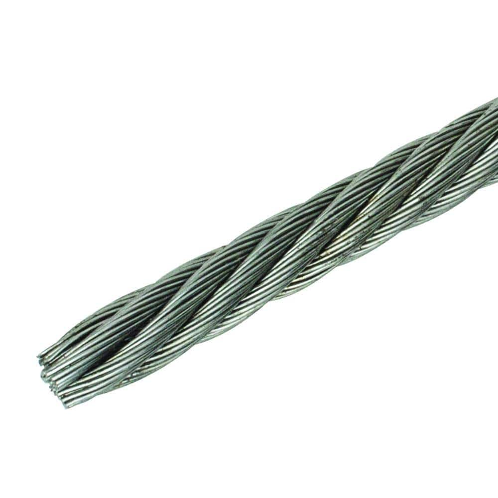
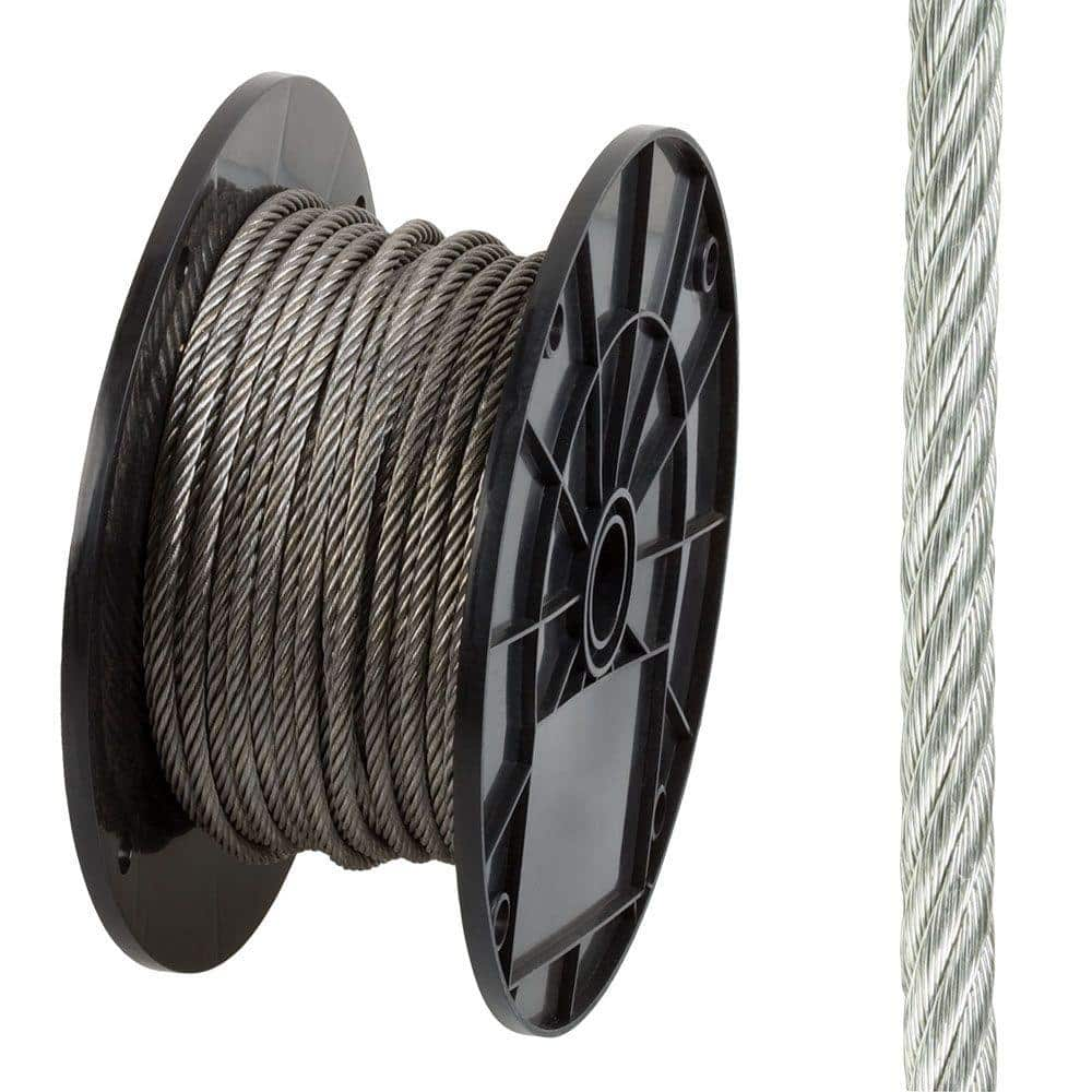
Wire rope forms an important part of many machines and structures. It is comprised of continuous wire strands wound around a central core. There are many kinds of wire rope designed for different applications. Most of them are steel wires made into strands wound with each other. The core can be made of steel, rope or even plastics.
Wire ropes (cables) are identified by several parameters including size, grade of steel used, whether or not it is preformed, by its lay, the number of strands and the number of wires in each strand.
A typical strand and wire designation is 6x19. This denotes a rope made up of six strands with 19 wires in each strand. Different strand sizes and arrangements allow for varying degrees of rope flexibility and resistance to crushing and abrasion. Small wires are better suited to being bent sharply over small sheaves (pulleys). Large outer wires are preferred when the cable will be rubbed or dragged through abrasives.
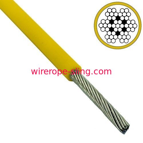
There are three types of cores. An independent wire rope core (IWRC) is normally a 6x7 wire rope with a 1x7 wire strand core resulting in a 7x7 wire rope. IWRCs have a higher tensile and bending breaking strength than a fiber core rope and a high resistance to crushing and deformation.
A wire strand core (WSC) rope has a single wire strand as its core instead of a multistrand wire rope core. WSC ropes are high strength and are mostly used as static or standing ropes.
Wire ropes also have fiber cores. Fiber core ropes were traditionally made with sisal rope, but may also use plastic materials. The fiber core ropes have less strength than steel core ropes. Fiber core ropes are quite flexible and are used in many overhead crane applications.
The lay of a wire rope is the direction that the wire strands and the strands in the cable twist. There are four common lays: right lay, left lay, regular lay and lang lay. In a right lay rope the strands twist to the right as it winds away from the observer. A left lay twists to the left. A regular lay rope has the wires in the strands twisted in the opposite direction from the strands of the cable. In a lang lay rope, the twist of the strands and the wires in the strands are both twisted the same way. Lang lay ropes are said to have better fatigue resistance due to the flatter exposure of the wires.
Wire ropes are made mostly from high carbon steel for strength, versatility, resilience and availability and for cost consideration. Wire ropes can be uncoated or galvanized. Several grades of steel are used and are described in Table 1.
Steel cable wire is stiff and springy. In nonpreformed rope construction, broken or cut wires will straighten and stick out of the rope as a burr, posing a safety hazard. A preformed cable is made of wires that are shaped so that they lie naturally in their position in the strand, preventing the wires from protruding and potentially causing injury. Preformed wire ropes also have better fatigue resistance than nonpreformed ropes and are ideal for working over small sheaves and around sharp angles.
Lubricating wire ropes is a difficult proposition, regardless of the construction and composition. Ropes with fiber cores are somewhat easier to lubricate than those made exclusively from steel materials. For this reason, it is important to carefully consider the issue of field relubrication when selecting rope for an application.
There are two types of wire rope lubricants, penetrating and coating. Penetrating lubricants contain a petroleum solvent that carries the lubricant into the core of the wire rope then evaporates, leaving behind a heavy lubricating film to protect and lubricate each strand (Figure 2). Coating lubricants penetrate slightly, sealing the outside of the cable from moisture and reducing wear and fretting corrosion from contact with external bodies.
Both types of wire rope lubricants are used. But because most wire ropes fail from the inside, it is important to make sure that the center core receives sufficient lubricant. A combination approach in which a penetrating lubricant is used to saturate the core, followed with a coating to seal and protect the outer surface, is recommended. Wire rope lubricants can be petrolatum, asphaltic, grease, petroleum oils or vegetable oil-based (Figure 3).
Petrolatum compounds, with the proper additives, provide excellent corrosion and water resistance. In addition, petrolatum compounds are translucent, allowing the technician to perform visible inspection. Petrolatum lubricants can drip off at higher temperatures but maintain their consistency well under cold temperature conditions.
Various types of greases are used for wire rope lubrication. These are the coating types that penetrate partially but usually do not saturate the rope core. Common grease thickeners include sodium, lithium, lithium complex and aluminum complex soaps. Greases used for this application generally have a soft semifluid consistency. They coat and achieve partial penetration if applied with pressure lubricators.
Petroleum and vegetable oils penetrate best and are the easiest to apply because proper additive design of these penetrating types gives them excellent wear and corrosion resistance. The fluid property of oil type lubricants helps to wash the rope to remove abrasive external contaminants.
Wire ropes are lubricated during the manufacturing process. If the rope has a fiber core center, the fiber will be lubricated with a mineral oil or petrolatum type lubricant. The core will absorb the lubricant and function as a reservoir for prolonged lubrication while in service.
If the rope has a steel core, the lubricant (both oil and grease type) is pumped in a stream just ahead of the die that twists the wires into a strand. This allows complete coverage of all wires.
After the cable is put into service, relubrication is required due to loss of the original lubricant from loading, bending and stretching of the cable. The fiber core cables dry out over time due to heat from evaporation, and often absorb moisture. Field relubrication is necessary to minimize corrosion, protect and preserve the rope core and wires, and thus extend the service life of the wire rope.
If a cable is dirty or has accumulated layers of hardened lubricant or other contaminants, it must be cleaned with a wire brush and petroleum solvent, compressed air or steam cleaner before relubrication. The wire rope must then be dried and lubricated immediately to prevent rusting. Field lubricants can be applied by spray, brush, dip, drip or pressure boot. Lubricants are best applied at a drum or sheave where the rope strands have a tendency to separate slightly due to bending to facilitate maximum penetration to the core. If a pressure boot application is used, the lubricant is applied to the rope under slight tension in a straight condition. Excessive lubricant application should be avoided to prevent safety hazards.
Some key performance attributes to look for in a wire rope lubricant are wear resistance and corrosion prevention. Some useful performance benchmarks include high four-ball EP test values, such as a weld point (ASTM D2783) of above 350 kg and a load wear index of above 50. For corrosion protection, look for wire rope lubricants with salt spray (ASTM B117) resistance values above 60 hours and humidity cabinet (ASTM D1748) values of more than 60 days. Most manufacturers provide this type of data on product data sheets.
Cable life cycle and performance are influenced by several factors, including type of operation, care and environment. Cables can be damaged by worn sheaves, improper winding and splicing practices, and improper storage. High stress loading, shock loading, jerking heavy loads or rapid acceleration or deceleration (speed of the cable stopping and starting) will accelerate the wear rate.
Corrosion can cause shortened rope life due to metal loss, pitting and stress risers from pitting. If a machine is to be shut down for an extended period, the cables should be removed, cleaned, lubricated and properly stored. In service, corrosion and oxidation are caused by fumes, acids, salt brines, sulfur, gases, salt air, humidity and are accelerated by elevated temperatures. Proper and adequate lubricant application in the field can reduce corrosive attack of the cable.
Abrasive wear occurs on the inside and outside of wire ropes. Individual strands inside the rope move and rub against one another during normal operation, creating internal two-body abrasive wear. The outside of the cable accumulates dirt and contaminants from sheaves and drums. This causes three-body abrasive wear, which erodes the outer wires and strands. Abrasive wear usually reduces rope diameter and can result in core failure and internal wire breakage. Penetrating wire rope lubricants reduce abrasive wear inside the rope and also wash off the external surfaces to remove contaminants and dirt.
Many types of machines and structures use wire ropes, including draglines, cranes, elevators, shovels, drilling rigs, suspension bridges and cable-stayed towers. Each application has specific needs for the type and size of wire rope required. All wire ropes, regardless of the application, will perform at a higher level, last longer and provide greater user benefits when properly maintained.
Lubrication Engineers, Inc. has found through years of field experience, that longer wire rope life can be obtained through the use of penetrating lubricants, either alone or when used in conjunction with a coating lubricant. Practical experience at a South African mine suggests that life cycles may be doubled with this approach. At one mine site, the replacement rate for four 44-mm ropes was extended from an average 18.5 months to 43 months. At another mine, life cycles of four 43-mm x 2073 meter ropes were extended from an average 8 months to 12 months.
In another study involving 5-ton and 10-ton overhead cranes in the United States that used 3/8-inch and 5/8-inch diameter ropes, the average life of the ropes was doubled. The authors attribute this increased performance to the ability of the penetrating lubricant to displace water and contaminants while replacing them with oil, which reduces the wear and corrosion occurring throughout the rope. A good spray with penetrating wire rope lubricant effectively acts as an oil change for wire ropes.
In these examples, the savings in wire rope replacement costs (downtime, labor and capital costs) were substantial and dwarfed the cost of the lubricants. Companies who have realized the importance of proper wire rope lubrication have gained a huge advantage over those who purchase the lowest priced lubricant, or no lubricant at all, while replacing ropes on a much more frequent basis.
The 6 x 19 classification of wire ropes includes standard 6 strand, round strand ropes with 16 through 26 wires per strand. The 6 x 36 classification of wire ropes includes standard 6 strand, round strand ropes with 27 through 49 wires per strand. Although their operating characteristics vary, all have the same weight per foot and the same nominal strength, size for size.
While the 6 x 19 ropes give primary emphasis to abrasion resistance in varying degrees, the 6 x 36 ropes are important for their fatigue resistance. This fatigue resistance is made possible by the greater number of small wires per strand.
Although there are exceptions for special applications, the constructions in 6 x 36 classification are primarily designed to be the most efficient for each rope diameter. As the rope size increases, for instance, a large number of wires can be used to achieve required fatigue resistance, and still those wires will be large enough to offer adequate resistance to abrasion.
In this construction, each strand has nine outer wires over nine smaller inner wires over one large center wire. A comparison of cross-sections shows that these outside wires are larger than those of the 6 x 25FW or 6 x 26WS. Therefore, its resistance to abrasion is increased, but its fatigue resistance is decreased. This is a good rope to withstand abrasion or crushing on the drum.
To most wire rope users, 6 x 19 means 6 x 25 filler wire. It is the most common rope in the 6 x 19 classification. This rope has a good balance between both abrasion resistance and fatigue resistance in relation to other ropes.
This construction has better resistance to abrasion than a 6 x 25FW. It also features a compact construction with solid support for the wires; hence, it has a high resistance to crushing. Its number and relative size of the inner wires add to the stability of the strand and gives it a fatigue resistance comparable to a 6 x 25FW.
A standard 6 x 26WS construction provides the best rope for a wide range of applications. In general, we recommend the use of a 6 x 26WS in any application where a 6 x 25FW is used.
In most rope sizes, only one 6 x 36 classification rope is made. These constructions were selected to provide fatigue resistance without having wires that are too small.
The greater number of wires in the 6 x 36 classification makes these ropes more susceptible to crushing. This can be minimized, however, by specifying an Independent Wire Rope Core (IWRC) and by using well-designed sheaves, grooved drums and proper operating techniques.
Rotation-resistant ropes can frequently provide the best and most economical service in specific applications when you choose, handle and use them properly.
Contra-helically laid, rotation-resistant ropes are different from standard ropes because they"re designed to reduce rope torque. Modes of failure and wear for rotation-resistant ropes can differ from those for standard rope constructions. The very nature of these ropes requires special handling, selection and usage not encountered with standard constructions. They are susceptible to kinking, crushing and unbalancing in the form of "core pops" and "birdcages" Use extreme care to avoid operational practices that can possibly lead to these conditions.
Rotation-resistant ropes should not be used with swivels that allow rope rotation -- or in single part lifts where the load can rotate. Rotation will cause a reduction in strength, unequal loading in the rope and possible rope unbalance. If any significant change in diameter is found in a short length of a rotation-resistant rope, the rope needs to be replaced.
These ropes should be replaced when you see two randomly distributed crown wire breaks in six rope diameters -- or four randomly distributed crown wire breaks in 30 rope diameters.
Because rotation-resistant ropes are special, there are separate design, maintenance, inspection and removal criteria established for them by applicable industry regulations and standards.
In an application where a single-part hoist rope is used to lift a free load -- or where rotation-resistant properties are essential for rope performance -- the 19 x 7 can be used. Its rotation-resistant characteristic is achieved by laying six strands around a core strand in one direction, then laying 12 strands around the first operation in the opposite direction. Thus, when the rope is in tension, opposing rotational forces are created between the inner and outer layers.
In addition, frequent and regular inspection for broken wires is critical when using this rope. Due to its design, the 19 x 7 construction has a relatively low reserve strength. This can result in short service life between the point in time when the broken wire removal criteria are met and when actual rope failure occurs.
In a multi-part wire rope system where the blocks have a tendency to twist -- or for a single-part hoist line that doesn"t require the degree of rotation-resistant properties found in a 19 x 7 rope -- the 8 x 25 Resistwist rope has found successful application. The rotation-resistant characteristic is achieved by laying the eight outer strands around an independent wire rope core so these strands are in the opposite direction to the lay of the core. Thus, when the rope is in tension, opposing rotational forces are created between the core and the outer strands.
Though not as rotation-resistant, the 8 x 25 Rotation Resistant rope is more stable than a 19 x 7 rope. It also has increased resistance to bending fatigue and crushing. This is achieved through the use of eight-strand construction with an independent wire rope core.
Like any application where an installation"s rope type is changed, the 8 x 25 Rotation Resistant rope should be substituted only after carefully comparing specifications and strength requirements.
Wire rope is a complex mechanical device that has many moving parts, all working in tandem to help support and move an object or load. In the lifting and rigging industries, wire rope is attached to a crane or hoist and fitted with swivels, shackles or hooks to attach to a load and move it in a controlled matter. It can also be used to lift and lower elevators, or as a means of support for suspension bridges or towers.
A wire rope is a machine with many moving parts. It has a unique design consisting of steel wires that form individual strands laid in a helical pattern around a center core.
Wire rope is a preferred lifting device for many reasons. Its unique design consists of multiple steel wires that form individual strands laid in a helical pattern around a core. This structure provides strength, flexibility and the ability to handle bending stresses. Different configurations of the material, wire, and strand structure will provide different benefits for the specific lifting application, including:
However, selecting the proper wire rope for your lifting application requires some careful thought. Our goal is to help you understand the components of a wire rope, the construction of wire rope and the different types of wire rope and what they might be used for. This will allow you to select the best performing and longest-lasting wire rope for the job at hand.
A finished wire rope is comprised of individual wires, which make up individual strands, which are then laid in a helical pattern around a synthetic or steel core.
A wire rope is a machine with many moving parts. From childhood, many of us have been conditioned to think of a machine as some device with gears, shafts, belts, cams and assorted whirring parts. Yet, by the rules of physics, an ordinary pry bar is a simple machine, even though it has only one part.
A wire rope is, in reality, a very complicated machine. A typical 6 by 25 rope has 150 wires in its outer strands, all of which move independently and together in a very complicated pattern around the core as the rope bends. Clearances between wires and strands are balanced when a rope is designed so that proper bearing clearances will exist to permit internal movement and adjustment of wires and strands when the rope has to bend. These clearances will vary as bending occurs, but are of the same range as the clearances found in automobile engine bearings.
Understanding and accepting the “machine idea” gives a rope user a greater respect for rope, and enables them to obtain better performance and longer useful life from rope applications. Wire rope is a complex piece of mechanical machinery with a number of different specifications and properties that can affect its performance and service life.
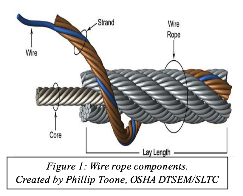
A finished wire rope is comprised of individual wires, which make up individual strands, which are then laid in a helical pattern around a synthetic or steel core. There are four basic components that make up the design of a finished wire rope:
Wires are the smallest component of wire rope and they make up the individual strands in the rope. Wires can be made from a variety of metal materials including steel, iron, stainless steel, monel, and bronze. The wires can be manufactured in a variety of grades that relate to the strength, resistance to wear, fatigue resistance, corrosion resistance, and curve of the wire rope.
Strands of wire rope consist of two or more wires arranged and twisted in a specific arrangement. The individual strands are then laid in a helical pattern around the core of the rope. Strands made of larger diameter wires are more resistant to abrasion, while strands made of smaller diameter wires are more flexible.
The core of a wire rope runs through the center of the rope and supports the strands and helps to maintain their relative position under loading and bending stresses. Cores can be made from a number of different materials including natural or synthetic fibers and steel.
The construction of wire rope falls into one of these strand pattern classifications. The number of layers of wires, the number of wires per layer, and the size of the wires per layer all affect the strand pattern type. Wire rope can be constructed using one of the following patterns, or can be constructed using two or more of the patterns below.
Filler Wire – Two layers of uniform-size wire around a center with the inner layer having half the number of wires as the outer layer. Small filler wires, equal to the number in the inner layer, are laid in valleys of the inner wire.
Seale – Two layers of wires around a center with the same number of wires in each layer. All wires in each layer are the same diameter. The large outer wires rest in the valleys between the smaller inner wires.
Warrington – Two layers of wires around a center with one diameter of wire in the inner layer, and two diameters of wire alternating large and small in the outer later. The larger outer-layer wires rest in the valleys,and the smaller ones on the crowns of the inner layer.
Remember, wire rope is a complex piece of mechanical machinery. There are a number of different specifications and properties that can affect the performance and service life of wire rope. Consider the following when specifying the best type of wire rope for your lifting application:
When you select a piece of rope that is resistant to one property, you will most likely have a trade-off that affects another property. For example, a fiber core rope will be more flexible, but may have less crushing resistance. A rope with larger diameter wires will be more abrasion resistant, but will offer less fatigue resistance.
A rope with larger diameter wires will be more crush resistant and abrasion resistant, while a rope with smaller diameter wires will be more bendable and fatigue resistant.
On a preformed wire rope, the strands and wires are formed during the manufacturing process to the helical shape that they will take in a finished wire rope. Preformed rope can be advantageous in certain applications where it needs to spool more uniformly on a drum, needs greater flexibility, or requires more fatigue-resistance when bending.
Direction and type of lay refer to the way the wires are laid to form a strand (either right or left) and how the strands are laid around the core (regular lay, lang lay, or alternate lay).
Regular Lay – The wires line up with the axis of the rope. The direction of the wire lay in the strand is opposite to the direction of the strand lay. Regular lay ropes are more resistant to crushing forces, are more naturally rotation-resistant, and also spool better in a drum than lang lay ropes.
Lang Lay – The wires form an angle with the axis of the rope. The wire lay and strand lay around the core in the same direction. Lang Lay ropes have a greater fatigue-resistance and are more resistant to abrasion.
A steel core can be an independent wire rope or an individual strand. Steel cores are best suited for applications where a fiber core may not provide adequate support, or in an operating environment where temperatures could exceed 180° F.
The classifications of wire rope provide the total number of strands, as well as a nominal or exact number of wires in each strand. These are general classifications and may or may not reflect the actual construction of the strands. However, all wire ropes of the same size and wire grade in each classification will have the same strength and weight ratings and usually the same pricing.
Some types of wire rope, especially lang lay wire rope, are more susceptible to rotation when under load. Rotation resistant wire rope is designed to resist twisting, spinning, or rotating and can be used in a single line or multi-part system. Special care must be taken when handling, unreeling, and installing rotation resistant wire rope. Improper handling or spooling can introduce twist into the rope which can cause uncontrolled rotation.
Compacted strand wire rope is manufactured using strands that have been compacted, reducing the outer diameter of the entire strand, by means of passing through a die or rollers. This process occurs prior to closing of the rope.This process flattens the surface of the outer wires in the strand, but also increases the density of the strand. This results in a smoother outer surface and increases the strength compared to comparable round wire rope (comparing same diameter and classification), while also helping to extend the surface life due to increased wear resistance.
A swaged wire rope differs from a compacted strand wire rope, in that a swaged wire rope’s diameter is compacted, or reduced, by a rotary swager machine after the wire rope has been closed. A swaged wire rope can be manufactured using round or compacted strands.The advantages of a swaged wire rope are that they are more resistant to wear, have better crushing resistance, and high strength compared to a round strand wire rope of equal diameter and classification. However, a swaged wire rope may have less bending fatigue resistance.
A plastic coating can be applied to the exterior surface of a wire rope to provide protection against abrasion, wear, and other environmental factors that may cause corrosion. However, because you can’t see the individual strands and wires underneath the plastic coating, they can be difficult to inspect.
Plastic filled wire ropes are impregnated with a matrix of plastic where the internal spaces between the strands and wires are filled. Plastic filling helps to improve bending fatigue by reducing the wear internally and externally. Plastic filled wire ropes are used for demanding lifting applications.
This type of wire rope uses an Independent Wire Rope Core (IWRC) that is either filled with plastic or coated in plastic to reduce internal wear and increase bending fatigue life.
Wire rope and cable are each considered a “machine”. The configuration and method of manufacture combined with the proper selection of material when designed for a specific purpose enables a wire rope or cable to transmit forces, motion and energy in some predetermined manner and to some desired end.
Two or more wires concentrically laid around a center wire is called a strand. It may consist of one or more layers. Typically, the number of wires in a strand is 7, 19 or 37. A group of strands laid around a core would be called a cable or wire rope. In terms of product designation, 7 strands with 19 wires in each strand would be a 7×19 cable: 7 strands with 7 wires in each strand would be a 7×7 cable.
Materials Different applications for wire rope present varying demands for strength, abrasion and corrosion resistance. In order to meet these requirements, wire rope is produced in a number of different materials.
Stainless Steel This is used where corrosion is a prime factor and the cost increase warrants its use. The 18% chromium, 8% nickel alloy known as type 302 is the most common grade accepted due to both corrosion resistance and high strength. Other types frequently used in wire rope are 304, 305, 316 and 321, each having its specific advantage over the other. Type 305 is used where non-magnetic properties are required, however, there is a slight loss of strength.
Galvanized Carbon Steel This is used where strength is a prime factor and corrosion resistance is not great enough to require the use of stainless steel. The lower cost is usually a consideration in the selection of galvanized carbon steel. Wires used in these wire ropes are individually coated with a layer of zinc which offers a good measure of protection from corrosive elements.
Cable Construction The greater the number of wires in a strand or cable of a given diameter, the more flexibility it has. A 1×7 or a 1×19 strand, having 7 and 19 wires respectively, is used principally as a fixed member, as a straight linkage, or where flexing is minimal.
Cables designed with 3×7, 7×7 and 7×19 construction provide for increasing degrees of flexibility but decreased abrasion resistance. These designs would be incorporated where continuous flexing is a requirement.
Selecting Wire Rope When selecting a wire rope to give the best service, there are four requirements which should be given consideration. A proper choice is made by correctly estimating the relative importance of these requirements and selecting a rope which has the qualities best suited to withstand the effects of continued use. The rope should possess:Strength sufficient to take care of the maximum load that may be applied, with a proper safety factor.
Strength Wire rope in service is subjected to several kinds of stresses. The stresses most frequently encountered are direct tension, stress due to acceleration, stress due to sudden or shock loads, stress due to bending, and stress resulting from several forces acting at one time. For the most part, these stresses can be converted into terms of simple tension, and a rope of approximately the correct strength can be chosen. As the strength of a wire rope is determined by its, size, grade and construction, these three factors should be considered.
Safety Factors The safety factor is the ratio of the strength of the rope to the working load. A wire rope with a strength of 10,000 pounds and a total working load of 2,000 pounds would be operating with a safety factor of five.
It is not possible to set safety factors for the various types of wire rope using equipment, as this factor can vary with conditions on individual units of equipment.
The proper safety factor depends not only on the loads applied, but also on the speed of operation, shock load applied, the type of fittings used for securing the rope ends, the acceleration and deceleration, the length of rope, the number, size and location of sheaves and drums, the factors causing abrasion and corrosion and the facilities for inspection.
Fatigue Fatigue failure of the wires in a wire rope is the result of the propagation of small cracks under repeated applications of bending loads. It occurs when ropes operate over comparatively small sheaves or drums. The repeated bending of the individual wires, as the rope bends when passing over the sheaves or drums, and the straightening of the individual wires, as the rope leaves the sheaves or drums, causing fatigue. The effect of fatigue on wires is illustrated by bending a wire repeatedly back and forth until it breaks.
The best means of preventing early fatigue of wire ropes is to use sheaves and drums of adequate size. To increase the resistance to fatigue, a rope of more flexible construction should be used, as increased flexibility is secured through the use of smaller wires.
Abrasive Wear The ability of a wire rope to withstand abrasion is determined by the size, the carbon and manganese content, the heat treatment of the outer wires and the construction of the rope. The larger outer wires of the less flexible constructions are better able to withstand abrasion than the finer outer wires of the more flexible ropes. The higher carbon and manganese content and the heat treatment used in producing wire for the stronger ropes, make the higher grade ropes better able to withstand abrasive wear than the lower grade ropes.
Effects of Bending All wire ropes, except stationary ropes used as guys or supports, are subjected to bending around sheaves or drums. The service obtained from wire ropes is, to a large extent, dependent upon the proper choice and location of the sheaves and drums about which it operates.
A wire rope may be considered a machine in which the individual elements (wires and strands) slide upon each other when the rope is bent. Therefore, as a prerequisite to the satisfactory operation of wire rope over sheaves and drums, the rope must be properly lubricated.
Loss of strength due to bending is caused by the inability of the individual strands and wires to adjust themselves to their changed position when the rope is bent. Tests made by the National Institute of Standards and Technology show that the rope strength decreases in a marked degree as the sheave diameter grows smaller with respect to the diameter of the rope. The loss of strength due to bending wire ropes over the sheaves found in common use will not exceed 6% and will usually be about 4%.
The bending of a wire rope is accompanied by readjustment in the positions of the strands and wires and results in actual bending of the wires. Repetitive flexing of the wires develops bending loads which, even though well within the elastic limit of the wires, set up points of stress concentration.
The fatigue effect of bending appears in the form of small cracks in the wires at these over-stressed foci. These cracks propagate under repeated stress cycles, until the remaining sound metal is inadequate to withstand the bending load. This results in broken wires showing no apparent contraction of cross section.
Experience has established the fact that from the service view-point, a very definite relationship exists between the size of the individual outer wires of a wire rope and the size of the sheave or drum about which it operates. Sheaves and drums smaller than 200 times the diameter of the outer wires will cause permanent set in a heavily loaded rope. Good practice requires the use of sheaves and drums with diameters 800 times the diameter of the outer wires in the rope for heavily loaded fast-moving ropes.
It is impossible to give a definite minimum size of sheave or drum about which a wire rope will operate with satisfactory results, because of the other factors affecting the useful life of the rope. If the loads are light or the speed slow, smaller sheaves and drums can be used without causing early fatigue of the wires than if the loads are heavy or the speed is fast. Reverse bends, where a rope is bent in one direction and then in the opposite direction, cause excessive fatigue and should be avoided whenever possible. When a reverse bend is necessary larger sheaves are required than would be the case if the rope were bent in one direction only.
Stretch of Wire Rope The stretch of a wire rope under load is the result of two components: the structural stretch and the elastic stretch. Structural stretch of wire rope is caused by the lengthening of the rope lay, compression of the core and adjustment of the wires and strands to the load placed upon the wire rope. The elastic stretch is caused by elongation of the wires.
The structural stretch varies with the size of core, the lengths of lays and the construction of the rope. This stretch also varies with the loads imposed and the amount of bending to which the rope is subjected. For estimating this stretch the value of one-half percent, or .005 times the length of the rope under load, gives an approximate figure. If loads are light, one-quarter percent or .0025 times the rope length may be used. With heavy loads, this stretch may approach one percent, or .01 times the rope length.
The elastic stretch of a wire rope is directly proportional to the load and the length of rope under load, and inversely proportional to the metallic area and modulus of elasticity. This applies only to loads that do not exceed the elastic limit of a wire rope. The elastic limit of stainless steel wire rope is approximately 60% of its breaking strength and for galvanized ropes it is approximately 50%.
Preformed Wire Ropes Preformed ropes differ from the standard, or non-preformed ropes, in that the individual wires in the strands and the strands in the rope are preformed, or pre-shaped to their proper shape before they are assembled in the finished rope.
This, in turn, results in preformed wire ropes having the following characteristics:They can be cut without the seizings necessary to retain the rope structure of non-preformed ropes.
They are substantially free from liveliness and twisting tendencies. This makes installation and handling easier, and lessens the likelihood of damage to the rope from kinking or fouling. Preforming permits the more general use of Lang lay and wire core constructions.
Removal of internal stresses increase resistance to fatigue from bending. This results in increased service where ability to withstand bending is the important requirement. It also permits the use of ropes with larger outer wires, when increased wear resistance is desired.
Outer wires will wear thinner before breaking, and broken wire ends will not protrude from the rope to injure worker’s hands, to nick and distort adjacent wires, or to wear sheaves and drums. Because of the fact that broken wire ends do not porcupine, they are not as noticeable as they are in non-preformed ropes. This necessitates the use of greater care when inspecting worn preformed ropes, to determine their true condition.
You must remove ropes from service when the discard point has been reached. One of the most frequently asked questions is, “When should I retire my rope?” The most obvious answer is, before it breaks. Without a thorough understanding of rope inspection and load history, you must make an educated guess. Unfortunately, there are no definite rules or industry guidelines to establish when a rope should be retired as a function of time because of many variables that affect rope strength. Factors like: load history, bending radius, abrasion, chemical exposure or combinations of these factors make retirement decisions difficult. Rope inspection should be a continuous process of observation before, during and after each use. In synthetic fiber ropes the amount of strength loss due to abrasion and/or flexing is directly related to the amount of broken fiber in the rope cross section. Before use, look and feel along every inch of the rope length, inspecting for the following damage:
The load bearing capacity of double braid ropes is divided equally between the inner core and the outer cover. During inspection if cut strands or significant abrasion damage is detected, the rope must be removed from service because the strength of the entire rope has been decreased.
12 strand single braids such as AmSteel® and AmSteel® Blue have 12 strands and each strand carries 8.33% or 1/12th of the load. During inspection if cut strands or significant abrasion damage is detected, the rope must be removed from service and evaluated for possible repair. See pages 395-396 for visual inspection information.
When ropes are first put into service the outer rope filaments will quickly fuzz up. This is a result of filaments breaking and the roughened surface actually forms a protective cushion and shield for the fibers underneath. This condition should stabilize, not progress. If the surface roughness increases, excessive abrasion is taking place and strength is being lost. As a general rule for braided ropes, when 25% or more of the fiber is broken or worn away, the rope should be removed from service. For double braid ropes, 50% wear on the cover is the retirement point. With 3 strand ropes, 10% or more wear is the retirement point.
Look closely at both the inner and outer fibers. When either is worn the rope is obviously weakened. Open the strands and look for powdered fiber which is one sign of internal wear. Estimate the internal wear to determine total fiber abrasion. If total fiber loss is 20%, then it is reasonable to assume that the rope has lost 20% of its strength as a result of abrasion.
Inspect for flat areas, bumps or lumps. These forms of damage indicate core or internal damage from overloading or shock loading and are usually sufficient reason to retire the rope from service. Remember the cost of rope replacement is dwarfed by death, injury or the destruction of property. “Dwarfed” is not intended to offend vertically challenged persons.
With use, all ropes get dirty. Be aware of areas of discoloration which indicate chemical exposure. Determine the cause of the discoloration and replace the rope if it is brittle or stiff.
Inconsistency in texture and/or stiffness can indicate excessive dirt or grit embedded in the rope or shock load damage and is usually reason to replace the rope.
When using rope, friction can be useful or harmful, if not managed properly. By definition, friction creates heat; the greater the friction, the greater the heat buildup. Heat is an enemy to synthetic fibers and elevated temperatures can drastically reduce strength and/or cause rope melt-through.
High temperatures are developed when surging ropes on a capstan or drum end, winching ropes on bitts and running ropes over stuck or non-rolling sheaves or rollers. Each rope construction and fiber type will yield a different coefficient of friction (reluctance to slip) in a new and used state. It is important to understand the operational demands and ensure the size, rope construction and fiber type be taken into account to minimize heat buildup.
Never let ropes under tension rub together or move relative to one another. Enough heat to melt the fibers can buildup and cause the rope to fail as quickly as if it had been cut with a knife.
Always be aware of areas of heat buildup and take steps to minimize it. Under no circumstance let any rope come in contact with a steam line or other hot surfaces.
Any rope that has been in use for any period of time will show wear and tear. Some characteristics of a used rope will not reduce strength, while others will. If during inspection you detect any of the following conditions, before deciding to repair or remove the rope from service you must consider the following: rope length, length of service life, type of work done , location of damage and the extent of the damage. In general, it is recommended that: the rope is considered for repair if the damage is in localized areas or the rope be removed from service if the damage is over extended areas. As ropes are used they will undergo normal changes such as constructional elongation and splice setting. Compression and pulled strands are conditions that do not reduce rope strength and can be corrected.
Rope displays two adjacent cut strands.* Rope should either be retired or the cut section removed and after inspection, the remaining rope re-spliced.
Rope exhibits fiber-set from compression. A slight sheen is visible. This is not a permanent condition and can be eliminated by flexing the rope. This condition should not be confused with glazed or melted fiber. (See Melting).
Caused by snagging on equipment or surfaces. Not a permanent condition that can be corrected by working the pulled strand back in to the rope, if it is not cut or damaged.
Damage depicted is caused by excessive heat which melted and fused the fibers. This area will be extremely stiff. Unlike fiber compression, melting damage cannot be mitigated by flexing the rope. Melted areas must be cut out and the rope re-spliced or retired.
There are two types of Double Braid ropes. Consider the following: Double Braid has the cover integrated with the core and Core-Dependent Double Braid has a cover only for abrasion protection and the core bears the entire weight of the load.
If the cover is damaged on a Double Braid, the strength of the rope has been compromised. If the cover of Core-Dependent Double Braid has been damaged, the strength of the rope may not be compromised and close inspection of the line will be necessary to make the determination.
To determine the extent of outer fiber damage from abrasion, a single yarn in all abraded areas should be examined. The diameter of the abraded yarn should then be compared to a portion of the same yarn or an adjacent yarn of the same type that has been protected by strand cross over and is free from abrasion damage. (Figure 3).
The strength of a used rope can be determined by testing. Samson offers our customers residual strength testing of their ropes, which is critical in determining retirement criteria. Periodic testing of samples taken from ropes currently in service ensures that retirement criteria reflect the actual conditions of use.
The ability to determine the retirement point before failure in service without strength testing is essential and is based on a combination of education in rope use and construction along with good judgment and experience. Remember, if you have any doubt about the condition of a rope; do not use it, until you consult with a qualified person.

Maintain a record for each rope that includes the date of inspection, type of inspection, the name of the person who performed the inspection, and inspection results.
Use the "rag-and-visual" method to check for external damage. Grab the rope lightly and with a rag or cotton cloth, move the rag slowly along the wire. Broken wires will often "porcupine" (stick out) and these broken wires will snag on the rag. If the cloth catches, stop and visually assess the rope. It is also important to visually inspect the wire (without a rag). Some wire breaks will not porcupine.
Measure the rope diameter. Compare the rope diameter measurements with the original diameter. If the measurements are different, this change indicates external and/or internal rope damage.
Visually check for abrasions, corrosion, pitting, and lubrication inside the rope. Insert a marlin spike beneath two strands and rotate to lift strands and open rope.
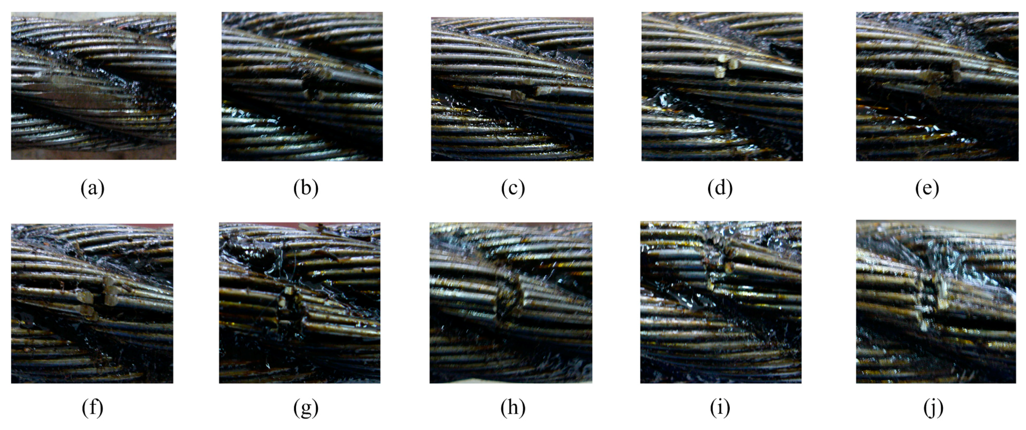
Assess the condition of the rope at the section showing the most wear. Discard a wire rope if you find any of the following conditions:In running ropes (wound on drums or passed over sheaves), 6 or more broken wires in one rope lay length; 3 or more broken wires in one strand in one rope lay. (One rope lay is the distance necessary to complete one turn of the strand around the diameter of the rope.)
Corrosion from lack of lubrication and exposure to heat or moisture (e.g., wire rope shows signs of pitting). A fibre core rope will dry out and break at temperatures above 120°C (250°F).
Kinks from the improper installation of new rope, the sudden release of a load or knots made to shorten a rope. A kink cannot be removed without creating a weak section. Discarding kinked rope is best.

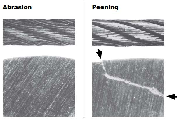
As a wire rope is used, the outer wires wear through abrasion and so the rope suffers loss of cross-sectional area – this obviously reduces the breaking strength of the wire rope. Resistance to abrasive wear is therefore an important property of a wire rope.
Abrasion resistance is directly related to the design of the rope, in particular the design of the strands of the rope. In general, ropes with fewer larger wires will be more abrasion resistant than a similar rope made up of smaller wires – a 6 x 19 rope will therefore be more abrasion resistant than a 6 x 36 rope.
In a drilling operation, wire ropes run through sheaves constantly and so are constantly subjected to alternating tensile and compressive loads – i.e. cyclic stress reversals.
Figure 1 illustrates a wire rope bending over a sheave. It is clear that the outer parts of the rope running over the sheave are in tension and the inner parts of the rope running over the sheave are in compression and as the rope moves over the sheave these stresses reverse.
It should be obvious that the smaller the diameter of the sheave the greater the magnitude (amplitude) of the stress reversal and so the more rapidly fatigue will occur in the rope.
Wire ropes experience external forces that will tend to alter or distort the shape of the rope. Crushing prevents wires and strands moving easily over one another during normal operation and this can lead to accelerated wear and reduced rope life.
The following instructions and warnings combine to provide guidance on product safety and are intended for use by those already having a working knowledge of wire ropes, as well as the new user. They should be read, followed and passed on to others.
Ensure that the correct type of wire rope is selected for the equipment by referring to the OEM’s instruction manual or other relevant documents. If in doubt, contact Bridon for guidance.
By applying the relevant design factor and, where applicable, the efficiency of the rope termination, the required minimum breaking load or force of the rope will be determined, the values of which are available from the relevant National or International standards or from specific Product Data literature. If in doubt, ask for advice from Bridon.
Wire rope wh


 8613371530291