
wire rope anchorage free sample
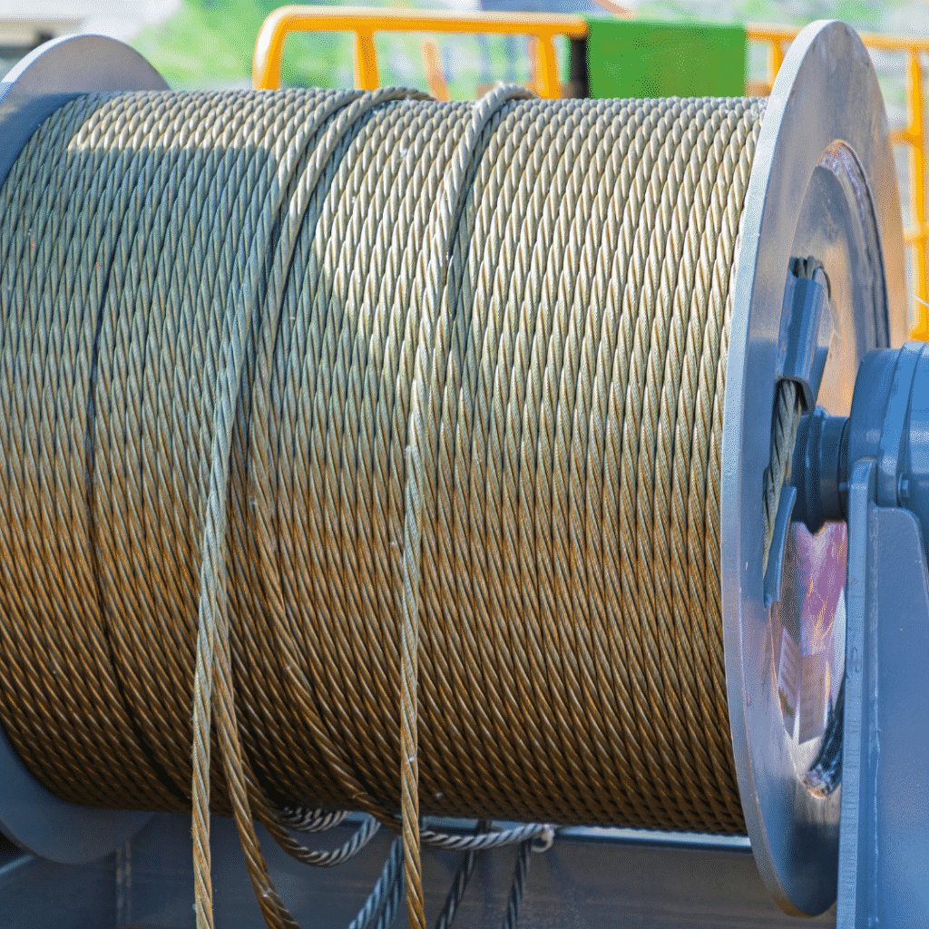
Nantong Fasten Metals Products Co., LTD is located in the coastal open city—Nantong which is in the lower area of the Yangtze River. We are a professional corporation which produces a variety of standards and types of galvanized steel wire rope, ungalvanized steel wire rope, steel-wire, stranded wire and spring steel wire. Our products mainly exported to Southeast Asia, the United States, Europe, the Middle East, Africa and other countries.

The following instructions and warnings combine to provide guidance on product safety and are intended for use by those already having a working knowledge of wire ropes, as well as the new user. They should be read, followed and passed on to others.
Ensure that the correct type of wire rope is selected for the equipment by referring to the OEM’s instruction manual or other relevant documents. If in doubt, contact Bridon for guidance.
By applying the relevant design factor and, where applicable, the efficiency of the rope termination, the required minimum breaking load or force of the rope will be determined, the values of which are available from the relevant National or International standards or from specific Product Data literature. If in doubt, ask for advice from Bridon.
Wire rope which bends around sheaves, rollers or drums will deteriorate through ‘bending fatigue’. Reverse bending and high speed will accelerate theprocess. Therefore, under such conditions select a rope with high bending fatigue resistance. Refer to Product Data Information, and if in doubt, ask for advice.
Abrasion weakens the rope by removing metal from both the inner and outer wires. Therefore, a rope with large outer wires should normally be selected.
Rope with a large number of small wires is more susceptible to corrosion than rope with a small number of large wires. Therefore, if corrosion is expected to have a significant effect on rope performance. The rope may have to be lubricated frequently in service or a galvanized rope may be selected.
‘Cabling’ of rope reeving due to block rotation can occur if the rope is incorrectly selected. Applications involving high lifts are particularly vulnerable to this condition, therefore, ropes specifically designed to resist rotation need to be selected.
Ropes which have high rotation characteristics must not be selected unless both ends of the rope are fixed or the load is guided and unable to rotate.
Ropes In the event that it is necessary to connect one rope to another (in series), it is essential that they have the required strength, are of the same type and both have the same lay direction (i.e. connect ‘right’ lay to ‘right’ lay).
Rope length and/or difference in length between two or more ropes used in a set may be a critical factor and must be considered along with rope selection.
Wire rope will elongate under load. Other factors, such as temperature, rope rotation and internal wear, will also have an effect. These factors should also be considered during rope selection.
Single layer round strand rope is normally supplied preformed. However, if a non-preformed rope is selected then personnel responsible for its installation and/or maintenance need to take particular care when handling such rope, especially when cutting.
Wire rope with a steel core should be selected if there is any evidence to suggest that a fiber core will not provide adequate support to the outer strands and/or if the temperature of the working environment may be expected to exceed 180°F.
For operating temperatures above 200°F, de-rating of the minimum breaking force of the rope is necessary (e.g. between 200°F and 400°F reduce by 10%; between 400°F and 600°F reduce by 25%; between 600°F and 800°F reduce by 35%).
Certain types of rope end terminations also have limiting operating temperatures and the manufacturer or Bridon should be consulted where there is any doubt. Ropes with aluminum ferrules must not be used at temperatures in excess of 300°F.
Unwrap the rope and examine the rope immediately after delivery to check its identification and condition and verify that it is in accordancewith the details on the Certificates and/or other relevant documents.
Check the rope diameter and examine any rope terminations to ensure that they are compatible with the equipment or machinery to which they are to be fitted.
Never store wire rope in areas subject to elevated temperatures as this may seriously affect its future performance. In extreme cases, its original as-manufactured strength may be severely reduced rendering it unfit for safe use.
Failure to do so may result in the rope becoming contaminated with foreign matter and start the onset of corrosion before the rope is even put to work.
Support the reel on a simple A-frame or cradle located on ground, which is capable of supporting the total mass of rope and reel. Ensure that the rope is stored where it is not likely to be affected by chemical fumes, steam or other corrosive agents.
Examine ropes in storage periodically and, when necessary, apply a suitable dressing which is compatible with the manufacturing lubricant. Contact the rope supplier, Bridon or original equipment manufacturer’s (OEM) manual for guidance on types of dressings available, methods of application and equipment for the various types of ropes and applications.
Ensure that the rope is stored and protected in such a manner that it will not be exposed to any accidental damage either during the storage period or when placing the rope in or taking it out of storage.
Failure to carry out or pay attention to any of the above could result in a loss of strength and/or a reduction in performance. In extreme cases, the rope may be unfit for safe use.
Failure to wear suitable protective clothing and equipment may result in skin problems from over exposure to certain types of rope lubricants and dressings; burns from sparks, rope ends, molten lubricants and metals when cutting ropes or preparing sockets for re-use; respiratory or other internal problems from the inhalation of fumes when cutting ropes or preparing sockets for re-use; eye injuries from sparks when cutting ropes; lacerations to the body from wire and rope ends; bruising of the body and damage to limbs due to rope recoil, backlash and any sudden deviation from the line of path of rope.
Ensure that the correct rope has been supplied by checking to see that the description on the Certificate is in accordance with that specified in the purchaser’s order.
For verification purposes, measure the diameter by using a suitable rope vernier fitted with jaws broad enough to cover not less than two adjacent strands. Take two sets of measurements spaced at least 3′ apart, ensuring that they are taken at the largest cross-sectional dimension of the rope. At each point, take measurements at right angles to each other
Examine the rope visually to ensure that no damage or obvious signs of deterioration have taken place during storage or transportation to the installation site.
Note:Grooves must have clearance for the rope and provide adequate circumferential support to allow for free movement of the strands and facilitate bending. When grooves become worn and the rope is pinched at the sides, strand and wire movement is restricted and the ability of the rope to bend is reduced.
When a new rope is fitted, a variation in size compared with the old worn rope will be apparent. The new rope may not fit correctly into the previously worn groove profile and unnecessary wear and rope distortion is likely to occur. This may be remedied by machining out the grooves before the new rope is installed. Before carrying out such action, the sheaves or drum should be examined to ensure that there will be sufficient strength remaining in the underlying material to safely support the rope.
If the coil is too large to physically handle it may be placed on a ‘swift’ turntable and the outside end of the rope pulled out allowing the coil to rotate.
Never pull a rope away from a stationary coil as this will induce turn into the rope and kinks will form. These will adversely affect rope performance.
Pass a shaft through the reel and place the reel in a suitable stand, which allows it to rotate and be braked to avoid overrun during installation. Where multi-layer coiling is involved, it may be necessary for the reel to be placed in equipment which has the capability of providing a back tension in the rope as it is being transferred from reel to drum. This is to ensure that the underlying (and subsequent) laps are wound tightly on the drum.
A kink can severely affect the strength of a six strand rope and can result in distortion of a Rotation Resistant rope leading to its immediate discard.
Ensure that the reel stand is mounted so as not to create a reverse bend during reeving (i.e. for a winch drum with an overlap rope, take the rope off the top of the reel).
Ensure that any equipment or machinery to be roped is correctly and safely positioned and isolated from normal usage before installation commences. Refer to the OEM’s instruction manual and the relevant ‘Code of Practice’.
When releasing the outboard end of the rope from a reel or coil, ensure that this is done in a controlled manner. On release of the bindings and servings used for packaging, the rope will want to straighten itself from its previously bent position. Unless controlled, this could be a violent action. Stand clear.
If installing the new rope with the aid of an old one, one method is to fit a wire rope sock (or stocking) to each of the rope ends. Always ensure that the open end of the sock (or stocking) is securely attached to the rope by a serving or alternatively by a clip. Connect the two ends via a length of fiber rope of adequate strength in order to avoid turn being transmitted from the old rope into the new rope. Alternatively, a length of fiber or steel rope of adequate strength may be reeved into the system for use as a pilot / messenger line. Do not use a swivel during the installation of the rope.
Monitor the rope carefully as it is being pulled into the system and make sure that it is not obstructed by any part of the structure or mechanism which may cause the rope to come free.
Take particular care and note the manufacturer’s instructions when the rope is required to be cut. Apply secure servings on both sides of the cut mark.
Ensure that the length of serving is at least equal to two rope diameters. (Note:Special servings are required for spiral ropes, i.e. spiral strand and locked coil.)
One serving either side of the cut is normally sufficient for preformed ropes. For non-preformed ropes, (i.e. Rotation Resistant ropes) a minimum of two servings each side of the cut will be necessary.
Arrange and position the rope in such a manner that at the completion of the cutting operation the rope ends will remain in position, thus avoiding any backlash or any other undesirable movement.
Cut the rope with a high speed abrasive disc cutter. Other suitable mechanical or hydraulic shearing equipment may be used although not recommended when a rope end is required to be welded or brazed.
Ensure adequate ventilation to avoid any build-up of fumes from the rope and its constituent parts including any fiber core (natural or synthetic) any rope lubricant(s) and any synthetic filling and/or covering material.
Rope produced from carbon steel wires in the form shipped is not considered a health hazard. During subsequent processing (e.g. cutting, welding, grinding, cleaning), dust and fumes may be produced which contain elements which may affect exposed workers.
The products used in the manufacture of steel wire ropes for lubrication and protection present minimal hazard to the user in the form shipped. The user must however, take reasonable care to minimize skin and eye contact and also avoid breathing their vapor and mist.
When terminating a rope end with a wedge socket, ensure that the rope tail cannot withdraw through the socket by securing a clamp to the tail or by following the manufacturer’s instructions. The tail length should be a minimum of 20 rope diameters for all Rotation Resistant wire rope and a minimum of 6 rope diameters for 6 and 8 strand ropes.
The loop back method uses a rope grip and the loop should be lashed to the live part of rope by a soft wire serving or tape to prevent flexing of the rope in service.
When coiling a rope on a plain (or smooth) barrel drum, ensure that each lap lies tightly against the preceding lap. The application of tension in the rope greatly assists in the coiling of the rope.
The direction of coiling of the rope on the drum is important, particularly when using plain barrel drums, and should be related to the direction of lay of the rope in order to induce close coiling.
When multi-layer spooling has to be used it should be realized that after the first layer is wound on a drum, the rope has to cross the underlying rope in order to advance across the drum in the second layer. The points at which the turns in the upper layer cross those of the lower layer are known as the cross-over points and the rope in these areas is susceptible to increased abrasion and crushing. Care should be taken when installing a rope on a drum and when operating a machine to ensure that the rope is spooled and layered correctly.
Check the state of re-usable rope end terminations for size, strength, defects and cleanliness before use. Nondestructive testing may be required depending on the material and circumstances of use. Ensure that the termination is fitted in accordance with the OEM’s instruction manual or manufacturer’s instructions. When re-using a socket and depending on its type and dimensions, the existing cone should be pressed out. Otherwise, heat may be necessary.
‘Run in’ the new rope by operating the equipment slowly, preferably with a low load, for several cycles. This permits the new rope to adjust itself gradually to working conditions.
Note:Unless otherwise required by a certifying authority, the rope should be in this condition before any proof test of the equipment or machinery is carried out.
If samples are required to be taken from the rope for subsequent testing and/or evaluation, it is essential that the condition of the rope is not disturbed. Refer to the instructions given in 4.12 and, depending on the rope type and construction, any other special manufacturer’s instructions.
Inspect the rope and related equipment at the beginning of every work period at least daily in most instances and particularly following any incident which could have damaged the rope or installation.
The entire length of rope should be inspected and particular attention paid to those sections that experience has proven to be the main areas of deterioration. Excessive wear, broken wires, distortion and corrosion are the usual signs of deterioration. For a more detailed examination, special tools are necessary, which will also facilitate internal inspection.
In the case of ropes working over drums or sheaves, it is particularly necessary to examine those areas entering or leaving the grooves when maximum loads (i.e. shock loads) are experienced, or those areas which remain for long periods in exposed places, such as over a jib head sheave.
On some running ropes, but particularly relevant to standing ropes (e.g. pendant ropes), the areas adjacent to terminations should be given special attention by rope diameter measurements and visual examination for broken wires and corrosion.
Note:Shortening the rope repositions the areas of maximum deterioration in the system. Where conditions permit, begin operating with a rope which has a slightly longer length than necessary in order to allow for periodic shortening.
When a non-preformed rope or multi-layer rope is used with a wedge socket and is required to be shortened, it is essential that the end of the rope is secured by welding or brazing before the rope is pulled through the main body of the socket to its new position.
Slacken the wedge in the socket. Pass the rope through the socket by an amount equivalent to the crop length or sample required. Note that the original bent portion of the rope must not be retained within the wedge socket. Replace the wedge and pull up the socket. Prepare and cut in accordance with section 4.12. Ensure that the rope tail cannot withdraw through the socket, see section 4.13.
Failure to observe this instruction will result in a significant deterioration in the performance of the rope and could render the rope completely unfit for further service.
In cases where severe rope wear takes place at one end of a wire rope, the life of the rope may be extended by changing round the drum end with the load end, i.e. turning the rope ‘end for end’ before deterioration becomes excessive.
Remove broken wires as they occur by bending backwards and forwards using a pair of pliers until they break deep in the valley between two outer strands. Wear protective clothing, such as overalls, industrial gloves, helmet, eye protectors and safety footwear during this operation.
Do not shear off the ends of broken wires with pliers as this will leave an exposed jagged edge, which is likely to damage other wires in the rope and lead to premature removal of the rope from service. Failure to wear adequate protective clothing could result in injury.
Note:Broken wires are a normal feature of service, more so towards the end of the rope’s life, resulting from bending fatigue and wear. The local break up of wires may indicate some mechanical fault in the equipment.
Do not operate an appliance if for any reason (e.g. rope diameter, certified breaking force, rope construction, length or strength and type of rope termination) the wire rope and its termination is considered unsuitable for the required duty.
Do not operate an appliance if the wire rope fitted has become distorted, been damaged or has deteriorated to a level such that discard criteria has been reached or is likely to be reached prior to normal expected life based on historical performance data.
Do not carry out any inspection, examination, dressing / lubrication, adjustment or any other maintenance of the rope while it is suspending a load, unless otherwise stated in the OEM’s instruction manual or other relevant documents.
Do not carry out any inspection or maintenance of the rope if the appliance controls are unattended unless the surrounding area has been isolated or sufficient warning signs have been posted within the immediate vicinity. If the appliance controls are attended, the authorized person must be able to communicate effectively with the driver or controller of the appliance during the inspection process.
The use of cleaning fluids (particularly solvent based) is likely to ‘cut back’ the existing rope lubricant leading to a greater quantity of lubricant accumulating on the surface of the rope. This may create a hazard in appliances and machinery which rely on friction between the rope and the drive sheave (e.g. elevators, friction winders and ski lifts).
Lubricants selected for in-service dressing must be compatible with the rope manufacturing lubricant and should be referenced in the OEM’s instruction manual or other documents approved by the owner of the appliance. If in doubt, contact Bridon.
Note:The authorized person carrying out a rope inspection must be capable of recognizing the potential loss of safe performance of such a rope in comparison with lubricated rope.
The authorized person responsible for carrying out wire rope maintenance must ensure that the ends of the rope are secure. At the drum end, this will involve checking the integrity of the anchorage and ensuring that there are at least three dead wraps tightly spooled.
Damage to, or removal of, component parts (mechanical or structural) caused by abnormal contact with wire rope can be hazardous to the safety of the appliance and/or the performance of the rope (e.g. damage to the drum grooving such that spooling is erratic and/or the rope is ‘pulled down’ into underlying layers, which might cause a dangerous condition or, alternatively, cause localized rope damage at ‘cross-over’ positions, which might then radically affect performance; loss / removal of wear plates protecting the structure leading to major structural damage by cutting and/or failure of the wire rope due to mechanical severance).
Following any periodic examination or routine or special inspection where any corrective action is taken the Certificate should be updated and a record made of the defects found, the extent of the changes and the condition of the rope.
Apply the following procedures for the selection and preparation of samples, from new and used lengths of rope, for the purpose of examination and testing to destruction.
Check that the rope end, from which the sample will be taken, is secured by welding or brazing. If not, select the sample length further away from the rope end and prepare new servings.
Handle the rope in accordance with the instructions given in Section 4. Serve the rope using the buried wire technique and apply a rope clamp or grip as close to the cut mark as practically possible. Do not use solder to secure the servings.
The rope should be cut with a high speed abrasive disc cutter or an oxyacetylene torch. Weld the rope ends of the sample as described in section 4.12, after which the clamp or grip can be removed.
The identification of the rope must be established and the sample suitably marked and packed. It is recommended that the 10′ sample is retained straight and secured to a wood pallet for transportation.
Failure to comply with these procedures will result in measured breaking force values which are not truly representative of the actual strength of the rope.
Note:The authorized competent person should also be familiar with the latest versions of ANSI, ASME or ISO Standards. Other standards and instructions covering rope discard may also be applicable. In the case of synthetic sheaves (or synthetic linings), refer to the OEM’s instruction manual or contact the sheave (or lining) manufacturer for specific discard criteria.
If a wire rope is removed from service at a level of performance substantially different to historically established performance data and without any obvious reason(s), contact Bridon for further guidance.
Only qualified and experienced personnel, taking the appropriate safety precautions and wearing the appropriate protective clothing, should be responsible for removing the wire rope.
Store discarded rope in a safe and secure location or compound and ensure that it is suitably marked to identify it as rope which has been removed from service and not to be used again.
Discarded rope can be a danger (e.g. protruding broken wires, excessive grease / lubricant and rope mass) to personnel and equipment if not handled correctly and safely during disposal.
(1) Lifelines, lanyards and deceleration devices should be attached to an anchorage and connected to the body-belt or body harness in the same manner as they would be when used to protect employees.
(3) For lanyard systems, the lanyard length should be 6 feet plus or minus 2 inches (1.83 m plus or minus 5 cm) as measured from the fixed anchorage to the attachment on the body belt or body harness.
(4) For rope-grab-type deceleration systems, the length of the lifeline above the centerline of the grabbing mechanism to the lifeline"s anchorage point should not exceed 2 feet (0.61 m).
(5) For lanyard systems, for systems with deceleration devices which do not automatically limit free fall distance to 2 feet (0.61 m ) or less, and for systems with deceleration devices which have a connection distance in excess of 1 foot (0.3 m) (measured between the centerline of the lifeline and the attachment point to the body belt or harness), the test weight should be rigged to free fall a distance of 7.5 feet (2.3 m) from a point that is 1.5 feet (.46 m) above the anchorage point, to its hanging location (6 feet below the anchorage). The test weight should fall without interference, obstruction, or hitting the floor or ground during the test. In some cases a non-elastic wire lanyard of sufficient length may need to be added to the system (for test purposes) to create the necessary free fall distance.
(ii) Lanyard length should be 6 feet plus or minus two inches (1.83 m plus or minus 5 cm) as measured from the fixed anchorage to the attachment on the body belt or body harness.
(iii) The test weight should fall free from the anchorage level to its hanging location (a total of 6 feet (1.83 m) free fall distance) without interference, obstruction, or hitting the floor or ground during the test.
(2) "Rope-grab-type deceleration devices." (i) Devices should be moved on a lifeline 1,000 times over the same length of line a distance of not less than 1 foot (30.5 cm), and the mechanism should lock each time.
(a) "Selection and use considerations." (1) The kind of personal fall arrest system selected should match the particular work situation, and any possible free fall distance should be kept to a minimum. Consideration should be given to the particular work environment. For example, the presence of acids, dirt, moisture, oil, grease, etc., and their effect on the system, should be evaluated. Hot or cold environments may also have an adverse effect on the system. Wire rope should not be used where an electrical hazard is anticipated. As required by the standard, the employer must plan to have means available to promptly rescue an employee should a fall occur, since the suspended employee may not be able to reach a work level independently.
(d) "Employee training considerations." Thorough employee training in the selection and use of personal fall arrest systems is imperative. Employees must be trained in the safe use of the system. This should include the following: application limits; proper anchoring and tie-off techniques; estimation of free fall distance, including determination of deceleration distance, and total fall distance to prevent striking a lower level; methods of use; and inspection and storage of the system. Careless or improper use of the equipment can result in serious injury or death. Employers and employees should become familiar with the material in this Appendix, as well as manufacturer"s recommendations, before a system is used. Of uppermost importance is the reduction in strength caused by certain tie-offs (such as using knots, tying around sharp edges, etc.) and maximum permitted free fall distance. Also, to be stressed are the importance of inspections prior to use, the limitations of the equipment, and unique conditions at the worksite which may be important in determining the type of system to use.
(e) "Instruction considerations." Employers should obtain comprehensive instructions from the supplier as to the system"s proper use and application, including, where applicable:
(6) Proper hook-up, anchoring and tie-off techniques, including the proper dee-ring or other attachment point to use on the body belt and harness for fall arrest;
(g) "Inspection considerations." As required by 1926.502(d)(21), personal fall arrest systems must be regularly inspected. Any component with any significant defect, such as cuts, tears, abrasions, mold, or undue stretching; alterations or additions which might affect its efficiency; damage due to deterioration; contact with fire, acids, or other corrosives; distorted hooks or faulty hook springs; tongues unfitted to the shoulder of buckles; loose or damaged mountings; non-functioning parts; or wearing or internal deterioration in the ropes must be withdrawn from service immediately, and should be tagged or marked as unusable, or destroyed.
(h) "Tie-off considerations." (1) One of the most important aspects of personal fall protection systems is fully planning the system before it is put into use. Probably the most overlooked component is planning for suitable anchorage points. Such planning should ideally be done before the structure or building is constructed so that anchorage points can be incorporated during construction for use later for window cleaning or other building maintenance. If properly planned, these anchorage points may be used during construction, as well as afterwards.
(i) Properly planned anchorages should be used if they are available. In some cases, anchorages must be installed immediately prior to use. In such cases, a registered professional engineer with experience in designing fall protection systems, or another qualified person with appropriate education and experience should design an anchor point to be installed.
(ii) In other cases, the Agency recognizes that there will be a need to devise an anchor point from existing structures. Examples of what might be appropriate anchor points are steel members or I-beams if an acceptable strap is available for the connection (do not use a lanyard with a snaphook clipped onto itself); large eye-bolts made of an appropriate grade steel; guardrails or railings if they have been designed for use as an anchor point; or masonry or wood members only if the attachment point is substantial and precautions have been taken to assure that bolts or other connectors will not pull through. A qualified person should be used to evaluate the suitable of these "make shift" anchorages with a focus on proper strength.
(2) Employers and employees should at all times be aware that the strength of a personal fall arrest system is based on its being attached to an anchoring system which does not reduce the strength of the system (such as a properly dimensioned eye-bolt/snap-hook anchorage). Therefore, if a means of attachment is used that will reduce the strength of the system, that component should be replaced by a stronger one, but one that will also maintain the appropriate maximum arrest force characteristics.
(3) Tie-off using a knot in a rope lanyard or lifeline (at any location) can reduce the lifeline or lanyard strength by 50 percent or more. Therefore, a stronger lanyard or lifeline should be used to compensate for the weakening effect of the knot, or the lanyard length should be reduced (or the tie-off location raised) to minimize free fall distance, or the lanyard or lifeline should be replaced by one which has an appropriately incorporated connector to eliminate the need for a knot.
(4) Tie-off of a rope lanyard or lifeline around an "H" or "I" beam or similar support can reduce its strength as much as 70 percent due to the cutting action of the beam edges. Therefore, use should be made of a webbing lanyard or wire core lifeline around the beam; or the lanyard or lifeline should be protected from the edge; or free fall distance should be greatly minimized.
(5) Tie-off where the line passes over or around rough or sharp surfaces reduces strength drastically. Such a tie-off should be avoided or an alternative tie-off rigging should be used. Such alternatives may include use of a snap-hook/dee ring connection, wire rope tie-off, an effective padding of the surfaces, or an abrasion-resistance strap around or over the problem surface.
(6) Horizontal lifelines may, depending on their geometry and angle of sag, be subjected to greater loads than the impact load imposed by an attached component. When the angle of horizontal lifeline sag is less than 30 degrees, the impact force imparted to the lifeline by an attached lanyard is greatly amplified. For example, with a sag angle of 15 degrees, the force amplification is about 2:1 and at 5 degrees sag, it is about 6:1. Depending on the angle of sag, and the line"s elasticity, the strength of the horizontal lifeline and the anchorages to which it is attached should be increased a number of times over that of the lanyard. Extreme care should be taken in considering a horizontal lifeline for multiple tie-offs. The reason for this is that in multiple tie-offs to a horizontal lifeline, if one employee falls, the movement of the falling employee and the horizontal lifeline during arrest of the fall may cause other employees to fall also. Horizontal lifeline and anchorage strength should be increased for each additional employee to be tied off. For these and other reasons, the design of systems using horizontal lifelines must only be done by qualified persons. Testing of installed lifelines and anchors prior to use is recommended.
(7) The strength of an eye-bolt is rated along the axis of the bolt and its strength is greatly reduced if the force is applied at an angle to this axis (in the direction of shear). Also, care should be exercised in selecting the proper diameter of the eye to avoid accidental disengagement of snap-hooks not designed to be compatible for the connection.
(j) "Snap-hook considerations." (1) Although not required by this standard for all connections until January 1, 1998, locking snaphooks designed for connection to suitable objects (of sufficient strength) are highly recommended in lieu of the nonlocking type. Locking snaphooks incorporate a positive locking mechanism in addition to the spring loaded keeper, which will not allow the keeper to open under moderate pressure without someone first releasing the mechanism. Such a feature, properly designed, effectively prevents roll-out from occurring.
(2) As required by 1926.502(d)(6), the following connections must be avoided (unless properly designed locking snaphooks are used) because they are conditions which can result in roll-out when a nonlocking snaphook is used:
(vi) Improper dimensions of the dee-ring, rebar, or other connection point in relation to the snaphook dimensions which would allow the snaphook keeper to be depressed by a turning motion of the snaphook.
(l) "Elongation and deceleration distance considerations." Other factors involved in a proper tie-off are elongation and deceleration distance. During the arresting of a fall, a lanyard will experience a length of stretching or elongation, whereas activation of a deceleration device will result in a certain stopping distance. These distances should be available with the lanyard or device"s instructions and must be added to the free fall distance to arrive at the total fall distance before an employee is fully stopped. The additional stopping distance may be very significant if the lanyard or deceleration device is attached near or at the end of a long lifeline, which may itself add considerable distance due to its own elongation. As required by the standard, sufficient distance to allow for all of these factors must also be maintained between the employee and obstructions below, to prevent an injury due to impact before the system fully arrests the fall. In addition, a minimum of 12 feet (3.7 m) of lifeline should be allowed below the securing point of a rope grab type deceleration device, and the end terminated to prevent the device from sliding off the lifeline. Alternatively, the lifeline should extend to the ground or the next working level below. These measures are suggested to prevent the worker from inadvertently moving past the end of the lifeline and having the rope grab become disengaged from the lifeline.
(n) "Other considerations." Because of the design of some personal fall arrest systems, additional considerations may be required for proper tie-off. For example, heavy deceleration devices of the self-retracting type should be secured overhead in order to avoid the weight of the device having to be supported by the employee. Also, if self-retracting equipment is connected to a horizontal lifeline, the sag in the lifeline should be minimized to prevent the device from sliding down the lifeline to a position which creates a swing hazard during fall arrest. In all cases, manufacturer"s instructions should be followed.

Lanyard means a flexible line of rope, wire rope, or strap that generally has a connector at each end for connecting the body belt or body harness to a deceleration device, lifeline, or anchorage.
Lifeline means a component of a personal fall protection system consisting of a flexible line for connection to an anchorage at one end so as to hang vertically (vertical lifeline), or for connection to anchorages at both ends so as to stretch horizontally (horizontal lifeline), and serves as a means for connecting other components of the system to the anchorage.
Personal fall arrest system means a system used to arrest an employee in a fall from a walking-working surface. It consists of a body harness, anchorage, and connector. The means of connection may include a lanyard, deceleration device, lifeline, or a suitable combination of these.
Rope grab means a deceleration device that travels on a lifeline and automatically, by friction, engages the lifeline and locks so as to arrest the fall of an employee. A rope grab usually employs the principle of inertial locking, cam/lever locking, or both.
Travel restraint (tether) line means a rope or wire rope used to transfer forces from a body support to an anchorage or anchorage connector in a travel restraint system.
Travel restraint system means a combination of an anchorage, anchorage connector, lanyard (or other means of connection), and body support that an employer uses to eliminate the possibility of an employee going over the edge of a walking-working surface.


 8613371530291