
wire rope bolt ends free sample

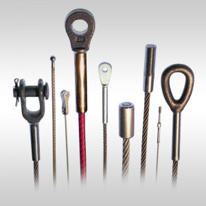
Lexco® Cable offers a large selection of wire rope and aircraft cable hardware and tools. Our hardware items are made for attaching cable and wire rope to structures, supports, and other cables and wire ropes. Unlike our cable fittings, this hardware is not crimped or swaged to the wire rope or cable but is attached through other means, generally through an eyehole on the hardware itself. Our tools are designed to make working with and attaching aircraft cable, wire rope, and hardware faster, easier, and safer.
All of our aircraft cable and wire rope hardware is available in bulk quantities or as part of a complete cable assembly. We specialize in cable assembly fabrication to save you time and money in additional production costs.
Request a quote for the aircraft cable or wire rope hardware items or tools you need, or contact Lexco® for more information. If you cannot find the hardware items or tools that you need in our online inventory, please contact your Lexco® Cable sales representative. We’ll be happy to help you find the ideal product for your application.

Wire rope is an extremely versatile mechanical device that can be used to help support and move an object or load. Whether for use on cranes or for other lifting applications, it’s important to have a solid understanding of the rigging components that are being used to attach to and lift a load.
As a rigger or end-user of wire rope, it’s necessary to understand the types of wire rope end termination, or treatments that can be used at the ends of a length of wire rope—one of the most common being wire rope clips.
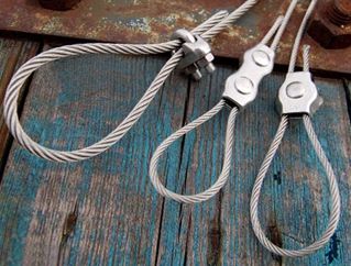
Wire rope clips can be used to form a load bearing eye at the end of a cable or wire rope, or to connect two cables together with a lap splice. Wire rope clips are popular because they can be installed in the field and provide 80-90% efficiency of the rope breaking strength, depending on the diameter of the wire rope.
As a general guideline, they are NOT to be used for making slings, as ASME B30.9 Slingsstandard states: “Mechanical wire rope terminations requiring periodic adjustment to maintain efficiency shall not be used to fabricate slings.”
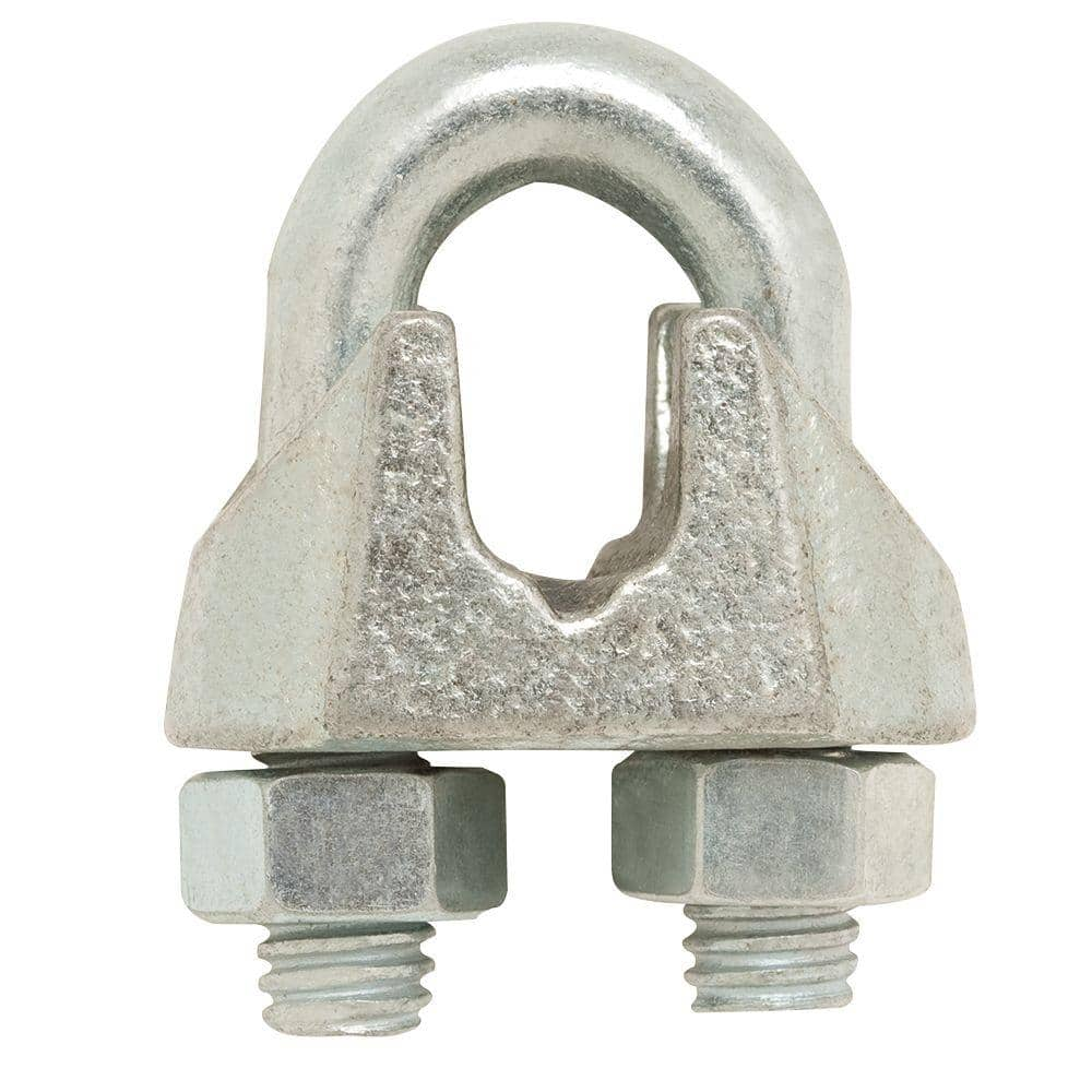
There are two main types of wire rope clips—U-Bolt and double saddle clips. U-Bolt wire rope clips are the most common and may be made of forged or malleable metal.
This type of wire rope clip is essentially a U-bolt, two nuts, and a metal base (saddle) that can be made from forged steel or cast iron. Careful consideration and attention must be given to the way U-bolt type wire rope clips are installed.
The base of the wire rope clip is made from forged steel. Forged clips are heated and hammered into the desired shape—resulting in a consistent grain structure in the steel. Forged wire rope clips are used for critical, heavy-duty, overhead loads such as winch lines, crane hoist lines, support lines, guy lines, towing lines, tie downs, scaffolds, etc.
Malleable wire rope clips are used for making eye termination assemblies only with right regular lay wire rope and only for light duty uses with small applied loads, such as hand rails, fencing, guard rails, etc. The base of the wire rope clips is made from malleable cast iron, which may fracture under heavy use and does not have the desirable metal properties of steel, or the beneficial grain structure that a forged base has.
Unfortunately, it is not uncommon to see a wire rope clip applied incorrectly. Some of the most common mistakes include:Not torquing to the manufacturer’s expectations
Wire rope clips require the use of a torque wrench in order to function properly. Torquing the nuts on the clips too much or too little can cause the clip to fail. If the clip is over-torqued, it could damage the threads of the wire rope. If the clip is under-torqued, the holding power of the clip is diminished and the wire rope could slip through.
There are a minimum number of clips required for use related to the wire rope diameter. Using less than the number of specified clips could result in decreased efficiency and possible failure.
Depending on the number and size of the wire rope clips, there is a proportional amount of space required between the placement on each clip on the rope.
There are two sides of a U-Bolt style wire rope clip: the saddle and the U-Bolt. When securing a wire rope eye, it is important to place the clip on the correct end of the rope.
A saying commonly used in rigging to help remember this is: “Never saddle a dead horse!” In other words, never put the saddle on the dead end of the rope.
The turnback is the portion of the wire rope eye that runs from the end of the bearing eye to the live end. Having less than the suggested amount of turnback will decrease the efficiency of the wire rope eye and could lead to failure.
It is important to be sure you are using the correct wire rope clip—forged or malleable wire rope clips—for the application. Malleable clips can only be used for non-critical uses, such as tension rope to form a perimeter around a parking lot.
If the use is critical—an application where, if there is a failure, you have potential injury or loss of life or damage to property—a forged clip must be used.
The clip size used—whether it be 1/8”, 3”, or otherwise—must match the diameter size of the wire rope. If it doesn’t, the wire rope could slip out of the clip.
After installing clips, it is necessary to regularly cycle the rope and retighten the clips. Monitoring the torque on the nuts is important, as they will loosen over repeated use.
Basic steps for installing a wire rope clip include:First, wrap the wire rope around the thimble or to form the eye, and turn back the correct amount of rope—as specified by the manufacturer.
Apply the first wire rope clip at the end of the dead end, with one base width of space. Use a torque wrench to tighten the nuts on the wire rope clip.
When applying the second clip (if required), place it as close to the eye loop or thimble as possible. Again, be sure to properly tighten the nuts of the clip with a torque wrench.
Wire rope clips are a common and necessary piece of rigging hardware when it comes to using wire rope and forming end terminations. They are used to form a wire rope eye or to connect two cables together. It’s important to understand how to correctly install a wire rope clip, as incorrect installation leads to decreased efficiency in the wire rope assembly.
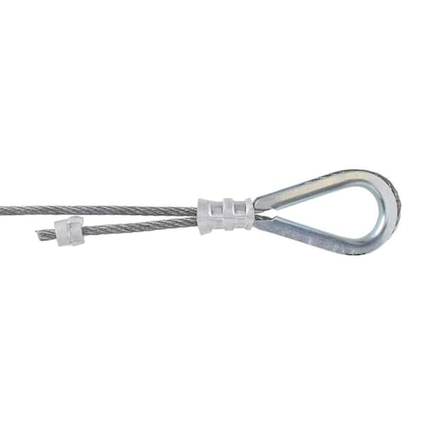
Wire rope thimbles also known as cable thimbles, are used for making reinforce loop(eyelet) with grips, clips or clamps by preventing fraying caused by friction at the bearing anchor point to protect and extend the service life of the wire rope or sling. They are just one of the many types of wire rope fittings (ferrules, wire rope clips, terminals, etc.).
Wire rope thimbles are available in a variety of strengths and materials(carbon steel and stainless steel, see our post on Surface Finish: 4 Common Types You Should Know) but mainly they come in two different duty grades.
If you use it in high moisture or corrosive environments, recommend our stainless steel wire rope thimbles which can offer resistance to corrosion on the surface, particularly in marine applications.
Simply wrap the end of the wire rope around the outer groove of the thimble, lace the dead end of the wire rope past the U-bolt of the wire rope grips or a wire rope ferrule crimp to hold onto the bearing anchor point at the end of the thimble to prevent fraying caused by friction.
Once in place, put another wire rope clip as near the loop you just wrapped over the thimble. Turn nuts firmly but do not yet tighten to the proper torque, we recommend using a crimping/swaging tool to compress the ferrule firmly onto the rope to hold your thimble loop securely.
Alternatively, you can use a wire rope ferrule crimp to secure your thimble in place. this method is quick and easy to install. For further information on installation using a wire rope ferrule please – click here
Wire rope thimbles are used in conjunction with cable and rope to protect the eyes and will allow for smooth rope guiding around natural curves. So that the most important thing is to make sure the thimble eye securely fastened. Here are some tips for correctly using wire rope thimble:
Make sure that the cable thimbles size properly and securely fastened in the eye of the loop, not too loose or too tighten, so they can create an extra layer of support to connect with other properly sized rigging fittings.
While you are using a vinyl coated cable, you should multiply the actual size of the cable, usually use a larger size thimble than normal, for the actual diameter is the thickness of the vinyl coating plus the inside wire rope diameter. For example, if you are using a 5/16″ vinyl coated cable that is coated to 3/8″ diameter, you’d want to use a 3/8″ wire rope thimble.

While these clips are not designed to be used in an overhead lifting situation (swage sleeves should be used instead), wire rope clips are heavy-duty wire rope clips that used for sustaining overhead loads. Examples include guy lines, support lines, scaffolding, etc.
U.S. Cargo Control offers two types of clips: standard (or U-Bolt) and fist-grip (or "double saddle"). Our line includes high-quality clips that work for any situation, including:
Install the first clip at the dead end side of the rope. The "U" side of the clip must always cover the dead end of the rope, and the "saddle" side of the clip on the live end of the rope. Place the nuts of the clip and tighten them using a torque wrench.
Place more clips on the rope if you need more than two on the wire rope. Be sure to space them evenly between the end clips. Finally, tighten the end clips and apply tension to reach the recommended torque for the wire rope.
(1) Cable laid and 6 x 19 and 6 x 37 slings shall have a minimum clear length of wire rope 10 times the component rope diameter between splices, sleeves or end fittings.
(c) Safe Operating Temperatures. Fiber core wire rope slings of all grades shall be permanently removed from service if they are exposed to temperatures in excess of 200o F. When nonfiber core wire rope slings of any grade are used at temperatures above 400o F, or below minus 60o F, the sling manufacturer"s recommendations shall be followed.
(3) Where rope clip attachments are used, they shall be made with U-bolts on the dead or short end of the rope and the saddle on the live end. The minimum number of clips for end attachments shall be not less than indicated in manufacturer"s tables, but in no case shall be less than three for any permanent installation. Clips shall be drop-forged steel. The clips shall be spaced at a distance equal to at least six times the diameter of the rope. All clip or clamp bolts shall be kept tight after tightening while rope is under tension.

(a) Factor of Safety. All rope to be used for regular hoisting shall be wire rope providing a factor of safety not less than five to one for material hoist and ten to one for personnel hoist when new, which shall be calculated by dividing the breaking strength of the wire rope as given in the manufacturer"s published tables, by the total load to be hoisted including the total weight of the wire rope in the shaft when fully let out, plus a proper allowance for impact and acceleration.
(b) Wire Rope Fastenings. Every wire rope used for hoisting shall be securely fastened at both ends and when in use shall not be fully unwound; at least three full turns shall remain on the drum so as to protect the end fastening at drum from overload. The wire rope end at the cage, skip or bucket shall be securely fastened by a properly made tapered socket joint, by an eye in the wire rope made with an oval thimble and wire rope clips, or by another method acceptable to the Division for this or similar service. If the wire rope clip method is used, the spacing and number used shall be as shown in Table - 1 for U-Bolts and in Table - 2 for Fist-Grip clips based upon using RRL or RLL wire rope, 6 x 19 or 6 x 37 Class, FC or IWRC; IPS or XIP. If Seale construction or similar large outer wire type construction in the 6 x 19 Class is to be used for sizes 1 inch and larger, add one additional clip. If a pulley (sheave) is used for turning back the wire rope, add one additional clip.
The number of clips shown also applies to rotation-resistant RRL wire rope, 8 x 19 Class, IPS, XIP, sizes 1-1/2 inch and smaller; and to rotation-resistant RRL wire rope, 19 x 7 Class, IPS, XIP (sizes 1-3/4 inch and smaller for U-Bolts and size 1-1/2 inch and smaller for Fist Grips).
(d) Splicing. Spliced wire rope shall not be used, except that the end may be attached to the load by the thimble and/or clip method, as provided in subsection (b) of this section.
(1) A safety hook, shackle or other means providing closed design protection shall form the attachment between rope and a bucket, cage, skip or load. The attachment shall be made so that the force of the hoist pull, vibration, misalignment, release of lift force, or impact will not disengage the connection. Moused or open-throat hooks with light safety latches do not meet this requirement.
(2) All wire rope fittings and connections shall be in accordance with the manufacturers" specifications and compatible with the type of wire rope used.
(g) Drum Flanges. The drum of any hoist used for hoisting shall have flanges which extend at least 2 inches radially beyond the last layer of rope when all the rope is coiled on the drum.
The present invention relates to a wire rope clip. In particular, the present invention is directed to a two-piece bolt and saddle for wire rope clips, which will grip and secure to the exterior surface of a rope or cable.
Previously existing wire rope clips have been forged and comprised of two identical clamps, each having a long threaded leg and an orifice for receiving a threaded leg of the corresponding clamp. The forged pieces were designed to be assembled together for clamping a wire rope. An example of such a wire rope clip is a FIST GRIP® clip manufactured by The Crosby Group, Inc.
Another example of a wire rope clamp is shown in U.S. Pat. No. 3,333,303 to St. Pierre. The St. Pierre wire rope clamp is constructed of two identical forgings secured together by a pair of conventional bolts. The St. Pierre wire rope clamp eliminates the need to forge a long leg on the clamps by replacing the leg with a standard bolt that passes through apertures formed within the clamps. The clamps are provided with a sunken hexhead socket for making the bolt heads non-rotatable. Although the sunken hexhead provided on the forged piece prevents rotation of the bolt, the sunken hexhead does not secure the bolts within the apertures of the unassembled clamps. Since the bolts are free to slide in or out of a clamp, difficulties arise in assembling the completed wire rope clamp.
It is an additional object to provide a wire rope clamp wherein a bolt is non-rotatable and is removably secured in a respective saddle so that the wire rope saddle may be assembled with greater ease without the difficulties associated with unintentional bolt disengagement from the saddle.
The wire rope clip of the present invention includes a first and second bolt each having a head, a threaded end and a plurality of splines. The splines are fashioned on the bolts proximate the head. The first bolt is received in a first orifice fashioned in a first saddle. The second bolt is received in a first orifice fashioned in a second saddle. The bolts are preferably press fit into the orifices whereby the splines on the bolts engage the walls of the first orifices so that the bolts are removably secured therein. The splines not only prevent rotation of the bolts, but also keep the bolts secured into their respective saddles.
Additionally, each saddle has a second orifice fashioned therein. The second orifice of the first saddle is for receiving the threaded end of the second bolt. The second orifice of the second saddle is for receiving the threaded end of the first bolt. The saddles are secured together by means of a first nut and a second nut that bias against the base of the second saddle and the base of the first saddle, respectively. Both the first saddle and the second saddle have a rope engaging surface fashioned between their respective first orifice and second orifice. Each rope engaging surface is fashioned on the surface opposite the base of each saddle. The wire rope clip is preferably constructed such that the first orifice on the first and second saddles are provided with a chamfered recess proximate the base of each respective saddle for receiving bolts having countersunk heads. By constructing the wire rope clip in this manner, the heads of the first and second bolts are flush with the base of the first and second saddles.
By constructing the two identical saddles, and securing the saddles together by means of the first bolt and the second bolt, a wire rope may be securely clamped by the wire rope clip.
Referring to the drawings in detail. FIG. 1 illustrates a preferred embodiment of first saddle 10 and first bolt 12 of the wire rope clip. First saddle 10 is provided with first orifice 14 and second orifice 16. Additionally, first saddle 10 is provided with rope engaging surface 18 and base 20 formed on an opposite side thereof.
In the preferred embodiment, first orifice 14 is formed having a chamfered recess 22 in base 20. First orifice 14 receives first bolt 12. First bolt 12 is preferably provided with head 24, threaded end 26 and splines 28. The splines 28 in the present embodiment are parallel to the axis of the first bolt. The head 24 is preferably countersunk to correspond with chamfered recess 22. Splines 28 or ribs engage wall 30 of first orifice 14. The splines 28 interfere with or dig into wall 30 of first orifice 14 for preventing first bolt 12 from rotating within first orifice 14 and for securing first bolt 12 within first orifice 14.
Although FIG. 1 displays first saddle 10 and first bolt 12, it is to be understood that, in the preferred embodiment, a second saddle and a second bolt are identical thereto and function in the same manner.
Referring to FIG. 2, an exploded side elevation view of a wire rope clip is provided. First saddle 10 is shown with first bolt 12 affixed thereto. First bolt 12 preferably is press fit within first orifice 14. It is noted that chamfered recess 22 receives countersunk head 24 as shown in FIG. 1, thereby resulting in flush surface 32. Opposite first saddle 10 is second saddle 34. Second saddle 34 is shown with second bolt 36 affixed thereto. Second bolt 36 is preferably press fit within first orifice 38 formed in second saddle 34. Additionally, second orifice 40 is provided in second saddle 34.
Second saddle 34 is provided with rope engaging surface 42 on one side and base 44 on an opposite side. Similar to first saddle 10, second saddle 34 also has a chamfered recess for receiving a countersunk head of second bolt 36. Second bolt 36 includes a threaded end 46 and splines or ribs, similar to first bolt 12. The union of the chamfered recess of second saddle 34 and the corresponding countersunk head of second bolt 36 result in flush surface 48 on base 44 of second saddle 34.
Threaded end 26 of first bolt 12 passes through second orifice 40 of second saddle 34 and engages first nut 50. Similarly, threaded end 46 of second bolt 36 passes through second orifice 16 of first saddle 10 for engaging second nut 52. First nut 50 biases against base 44 of second saddle 34 and second nut 52 biases against base 20 of first saddle 10. Therefore, rope engaging surface 18 of first saddle 10 is positioned opposite rope engaging surface 42 of second saddle 34. Rope engaging surfaces 18 and 42 are designed to engage a wire or other type of rope therebetween to secure the rope therein.
By utilizing the wire rope clip of the invention, first nut 50 and second nut 52 can be installed in such a way as to enable an operator to swing a wrench in a full arc for fast installation.
In practice, first bolt 12 is press fit or forced within first saddle 10 and splines 28 engage wall 30 within first orifice 14 of first saddle 10. Splines 28 prevent first bolt 12 from rotating within first saddle 10. Additionally, splines 28 removably secure first bolt 12 within first orifice 14. A similar assembly is constructed with respect to second saddle 34 and second bolt 36. By providing splines 28 for engaging wall 30 of first orifice 14 and for engaging the wall of second orifice 38 of second saddle 34, an operator is not inconvenienced by accidental disengagement of first bolt 12 from first sadole 10 and/or accidental disengagement second bolt 36 from second saddle 34.
First saddle 10 is positioned such that rope engaging surface 18 engages a wire rope and positions second saddle 34 such that threaded end 26 of first bolt 12 passes through second orifice 40 of second saddle 34. Additionally, second saddle 34 is positioned such that rope engaging surface 42 also engages a wire rope. First nut 50 is then threaded over threaded end 26 of first bolt 12 and second nut 52 is threaded onto threaded end 46 of second bolt 36. In this manner, two pieces of wire rope may be securely clamped by the wire rope clip of the present invention.
The wire rope clips may be utilized on turnback loops formed from a single piece of cable or to splice two pieces of wire rope together. It is to be understood that the wire rope clips may also be utilized for other applications where traditional wire rope clips have been utilized.

Employers must not use improved plow-steel wire rope and wire-rope slings with loads in excess of the rated capacities (i.e., working load limits) indicated on the sling by permanently affixed and legible identification markings prescribed by the manufacturer.
An eye splice made in any wire rope shall have not less than three full tucks. However, this requirement shall not operate to preclude the use of another form of splice or connection which can be shown to be as efficient and which is not otherwise prohibited.
Wire rope shall not be used if, in any length of eight diameters, the total number of visible broken wires exceeds 10 percent of the total number of wires, or if the rope shows other signs of excessive wear, corrosion, or defect.
Except for eye splices in the ends of wires and for endless rope slings, each wire rope used in hoisting or lowering, or in pulling loads, shall consist of one continuous piece without knot or splice.
Cable laid and 6 × 19 and 6 × 37 slings shall have a minimum clear length of wire rope 10 times the component rope diameter between splices, sleeves or end fittings.
Fiber core wire rope slings of all grades shall be permanently removed from service if they are exposed to temperatures in excess of 200 °F (93.33 °C). When nonfiber core wire rope slings of any grade are used at temperatures above 400 °F (204.44 °C) or below minus 60 °F (15.55 °C), recommendations of the sling manufacturer regarding use at that temperature shall be followed.
Wire rope slings shall have permanently affixed, legible identification markings stating size, rated capacity for the type(s) of hitch(es) used and the angle upon which it is based, and the number of legs if more than one.
- They could be used in loading and unloading of goods,mining equipment,forestry machinery,land transportation,hoisting machinery and etcSpecifications:Name: Wire Rope Clip
Size:M6Note:How thick the wire rope, please choose how thick the clip For example, 3mm steel wire rope please choose M3 sizePackage Content:10pcs Wire Rope ClipNote:- Please allow minor errors due to manual measurement. Thanks for your understanding.


 8613371530291