
wire rope break test free sample

The lifetime of wire rope is crucial in industry manufacturing, mining, and so on. The damage can be detected by using appropriate nondestructive testing techniques or destructive tests by cutting the part. For broken wires classification problems, this work is aimed at improving the recognition accuracy. Facing the defects at the exterior of the rope, a novel method for recognition of broken wires is firstly developed based on magnetic and infrared information fusion. A denoising method, which is adopted for magnetic signal, is proposed for eliminating baseline signal and wave strand. An image segmentation method is employed for parting the defects of infrared images. Characteristic vectors are extracted from magnetic images and infrared images, then kernel extreme learning machine network is applied to implement recognition of broken wires. Experimental results show that the denoising method and image segmentation are effective and the information fusion can improve the classification accuracy, which can provide useful information for estimating the residual lifetime of wire rope.
Wire ropes play an important role in many fields such as cranes, oil drilling rigs, elevators, and mine hoist. The safety of wire ropes is closely related to people’s life and resources loss as well as the normal operation of industry. Because of the complex structure of wire ropes and the diversity of application environment, it is difficult to evaluate the health of wire ropes in service [1, 2]. Thus, it is necessary to effectively and accurately perform the quantitative nondestructive testing (NDT) of wire rope by adopting proper methods.
At present, the NDT methods of wire rope include electromagnetic [3, 4], X-ray [5], acoustic [6–9], and optical [10] method [1]. X-ray apparatus has radioactive contamination; acoustic method detects wire rope by striking, which is simple but one-sided; CCD camera optical testing method can directly show the real defects through imaging, but it is susceptible to oil pollution; because of high sensitivity, high speed, and low cost, electromagnetic NDT method is widely used [11–14]. However, no single nondestructive testing technique can identify all kinds of defects. Infrared nondestructive testing does not contain dangerous radiation and has characteristic of noncontact; thus, it has widely applied in solving real problems in numerous areas [15].In addition, its popular application areas contain building sector [16, 17], aeronautics and astronautics [18], chemical industry [19], food [20], cultural heritage [21], and so on. Munoz et al. [22, 23] determined heat source dissipation from infrared thermographic measurements based on the heat diffusion equation provided by thermodynamics principles and identified damage evolution in carbon fibre reinforced composites combing acoustic emission and infrared thermography.
Magnetic flux leakage (MFL) detection of wire rope mainly includes the forward calculation model of MFL detection, pretreatment of MFL signal, and inversion of defect [24]. For example, Yan et al. [25] employed a three-dimensional finite element method (FEM) to analyze MFL signals. This method provided theoretical guidance for detection signal analysis and hardware design. Based on the magnetic dipole model, Yang [2] created the leakage magnetic field analysis models of single wire fracture, surface broken wire, and internal broken wire of wire rope, which provided the theoretical basis for the quantitative analysis of wire rope. Zhao and Zhang [11, 12] made FEM on the distribution of magnetic flux leakage of typical broken wire defects in steel cables, and obtained the relationship between MFL and detection distance, damage size, and internal broken wire. In [13, 14], a magnetic dipole model was established to design the prototype, which provided a theoretical basis for the quantification of defects. Through the FEM model of wire rope and the FEM simulation under different broken wires, DU et al. [26] studied the influence of different broken wires on the safety coefficient of wire rope.
Because actual MFL detection signals are polluted by many noise sources, it is necessary to preprocess the signals in order to reconstruct the defects. Zhang et al. [27, 28] utilized wavelet based on compressed sensing to denoise the strand wave, but it restored a lot of noise; then, they combined the Hilbert-Huang Transform (HHT) and Compressed Sensing Wavelet Filtering (CSWF) to reduce various background noises. Zheng and Zhang [29] exploited wavelet soft threshold to inhibit the noise; nevertheless, the denoising effect is poor. Then Zheng and Zhang [30] implemented Variational Mode Decomposition (VMD) and a wavelet transformation to remove noise from the raw MFL signals, which can effectively eliminate noise. Hong et al. [31] proposed an adaptive wavelet threshold denoising method based on a new threshold function, which achieved good denoising effect on the MFL signal of wire rope. To realize the visualization of defects, Zhao [13] utilized an adaptive notch filtering algorithm for suppressing wave noise.
To visualize and quantify defects and realize quantitative detection of broken wires, researchers need to implement defect inversion. In order to perform defect inversion, numerous scholars have used various methods. Through adopting the wavelet super-resolution reconstruction technique, the resolution of defect grayscale was improved in [32]. Zhang and Tan [33] proposed a super-resolution (SR) reconstruction method based on Tikhonov regular multiframe, which can effectively remain image features of defects while the axial resolution was reduced and circumferential resolution was increased. In [28, 32], researchers implemented classification of defects by adopting back propagation (BP) neural networks. However, BP was easy to fall into local minimum, which can lead to problems such as network underfitting and insufficient generalization ability. Wan et al. [34] investigated the theory on optimal wavelet packet with the Least Squares Support Vector Machine (LS-SVM) to diagnose elevator faults, which was then validated by the experiment. Zheng and Zhang and Qin et al. [29, 35] took the Support Vector Machine (SVM) with a radial basis function classified to conduct the fault pattern recognition, whereas this method was not very effective.
The researchers [15, 36] investigated the failures of steel ropes and defect of ferromagnetic specimens by means of thermovision. In [15], since the measurements required extremely sensitive thermovision technology, the method can detect the tight of ropes at certain conditions. In [34], the researchers developed a new active thermography technique, which can detect the defect in ferromagnetic steel specimens. The fusion of infrared and other information is effective and widely used. Kee and Oh et al. [16] combined air-coupled impact-echo and infrared thermography. It can improve effectiveness of the individual test data. Data fusion of ground-penetrating radar and infrared thermography improved the accuracy of detecting defects [37]. The researchers [38] combined finite element analysis with experimental data from infrared thermography, which provided accurate means to assess quantitatively the size and position of thermal imperfections. According to these, it is demonstrated that data fusion is effective. In this paper, fused data based on infrared thermography and magnetic is utilized to detect the number of broken wires.
Electromagnetic NDT for wire rope is susceptible to hardware design and magnetic signal processing. In [13, 14], the location and number of sensors can affect the quality of acquisition signal. Insufficient quantity will lead to the serious loss of MFL signal, while dense placement of sensors can lead to serious signal interference, resulting in difficulty of noise reduction. Meanwhile, the small broken wire defect information may be drowned out by noise. However, thermal infrared is a visualization method, which can intuitively grasp the surface damage state of wire rope and be closer to the actual damage pattern than magnetic data. Meanwhile, it is without the shortcomings of magnetic detection method and it can make up for the loss of small defects in magnetic information. Thus, the combination of the two methods supply more information for the damage and can avoid the loss of defect information.
To improve classification accuracy of broken wires and provide a reference for evaluating the service life of wire rope, the combination of infrared information and magnetic information is put forward for the first time to perform quantitative identification of wire rope. To processing magnetic signal, an algorithm based on Wavelet Total Variation (WATV) is proposed to remove noise from the raw MFL signals. The noise from high-frequency magnetic leakage, baseline drift, and strand waves can be suppressed by the proposed algorithm. To separate defects from infrared images, an image processing method based on distance is presented. After extracting statistical texture, invariant moment characteristics, and color moment, a fusion method based on kernel extreme learning machine (KELM) of decision level fusion is proposed to combine magnetic and infrared information. Experiment results show that the information fusion based on magnetic and infrared can improve the recognition rate of broken wires.
In the next sections, the platform to get data, the processing for magnetic data, steps for extracting infrared information, and recognition for broken wires after information fusion will be introduced in turn. In this paper, major innovations are as follows: (1) the proposed denoising algorithm based on WATV can eliminate noise generated by channel imbalance, the structure of wire ropes, and so on; (2) an infrared image segmentation algorithm based on distance is presented; and (3) information fusion combined magnetic with infrared to perform classification is firstly adopted.
In this part, through processing and fusing magnetic signal and infrared image, the classification for six kinds of broken wires is implemented. In this experiment, the number of broken wires is one, two, three, four, five, and seven. Many wires are wound into a strand, then it is wounded into a wire rope. The damage of the wire rope is related to the geometry and winding mode of the wire rope [1, 2, 13]. As shown in Figure 1, the structure of the wire rope is with a diameter of 28 mm. The length of the wire ropes is 6.5 m. The specimens used are 185, where the number of training samples is 139 and testing number is 46. The number of broken wires is from 1 to 5 and 7 wires, where the number of every samples set of broken wires is 30, 30, 32, 34, 35, and 34. The width of samples contains 2 mm, 5 mm, and 1.5 cm. The depth of defects is 1 mm. The type of defect is shown in Figure 2.
When there is no defect on wire rope and materials of the wire rope are uniform and identical, the magnetic flux through the cross-section of the wire rope should be equal in the axial direction. If there is a defect, the permeability at the defect becomes smaller, the magnetic field only passes through the air field and then returns to the inside of the wire rope; thus, magnetic leakage on surface is formed [12–14]. According to this principle, a magnetic flux leakage detection device is designed. Data collection contains magnetic signal acquisition and thermal infrared image acquisition. The specific devices and collecting procedures are as follows: the magnetic data acquisition device adopted contains Unsaturated Magnetic Excitation (UME) source, an array of 18 Giant Magnetoresistance (GMR) sensors, data acquisition unit, data storage, and control system [33].
As shown in Figure 4, data collection steps are as follows: After loading unsaturated magnetic field on wire rope, the weak MFL signal can be obtained through equal-space sampling. As the acquisition system moves along the axial direction of the wire rope, the photoelectric encoder produces the pulses. Then, the control system collects the defect information from 18 channels according to pulses. And the final magnetic data is stored in the SD card.
Because the rate of infrared radiation from defect location is different from that from nondefect location, the damage of wire rope can be detected. Infrared information acquisition system, as shown in Figure 5(a), includes heating unit and data collection. The heating unit is composed of the metal tube and tight wires. The metal tube is 40 mm in diameter and 20 cm in length. Wire is adopted to heat the metal tube. Infrared thermography is adopted to capture the images of defect information. The angle of camera should be adjusted according to the location of the defects to maintain the distance between the defect and the camera lens constant. The camera we adopted is thermal imager FLUKE TIX 660. The thermal resolution of the infrared camera is -20°C-1200°C. The distance between wire rope and camera is cm. The specific processes are as follows: after the wire is energized, the wire rope temperature rises by heating the metal tube. When the temperature of fault is maintained at about (°C), the defect images are taken by the infrared camera. Single images are acquired through the device shown in Figure 5(a). After installing the thermal infrared camera on the tripod, the defective part is heated, and the images of wire rope surface defect are obtained by panning the tripod. The focus of the image is formed by centering the defect and fixing the distance between the defect and the camera. The captured raw infrared picture is shown in Figure 5(b). (The defect is marked by a box.)
Infrared image acquisition: (a) schematic of infrared data acquisition device; (b) the raw infrared picture of defect; (c) thermal infrared image capture system; (d) testing platform for wire rope.
Using the system mentioned in Figure 4, raw UME signals can be obtained. As shown in Figure 6. Raw UME signals including incoherent baseline caused by channel imbalance, system noise, and strand wave noise produced by structure of wire rope should be filtered out to obtain pure defects information.
To eliminate the effect of uneven excitation on wire ropes and convert all the data with a uniform standard, normalization is necessary. Normalization is the basis of data visualization; hence, equation (18) is adopted to stretch the defects between 0–255.
Because circumferential data is acquired from 18 sensor channels, circumferential resolution is much lower than the axial one. The pixel count in circumferential is 18; however, the pixel count in axial is more than ten thousand. Three spline interpolations is employed to enhance the circumferential resolution, which increases the pixel count from 18 to 300. In addition, the procedure contributes to realize the visualization of defect images. The schematic of data after interpolations is shown in Figure 10. Then, we obtain gray image of leakage magnetic by converting the double data to unit 8. Figure 11 shows the grayscale image of a wire rope’s leakage magnetic field.
The image after texture filtering also exists strand wave, which makes trouble for feature extraction. The distances between strand waves are fixed according to the structure of wire rope, and the defects are located between strand waves. Therefore, an algorithm based on distance is proposed to part the damage. The algorithm can be described as follows:
(1)After binarization of image , locate the maximum and minimum values of the row and column with pixel value of 1 in the image, respectively. Then the image , as shown in Figure 13, is obtained: ( and are the maximum and minimum of line; and are the maximum and minimum of column).(2)For each line of image, find and :(3)Compute the distances for blocks whose pixel value is 1 by(4)For each line of the image , if the distance is between 10 and 70 and the block is larger than 12 (which can avoid the effect of oil pollution), maintain the line or set the line to zero. (The distance of two strands in wire rope is consist and strand wave shown in the image is also consist. Meanwhile, in order to reduce the effect of oil pollution on the segmentation defect, we choose the distance between 10 and 70 and the block larger than 12.)(5)Extract the defects of infrared images by finding the locations from that meet (4).
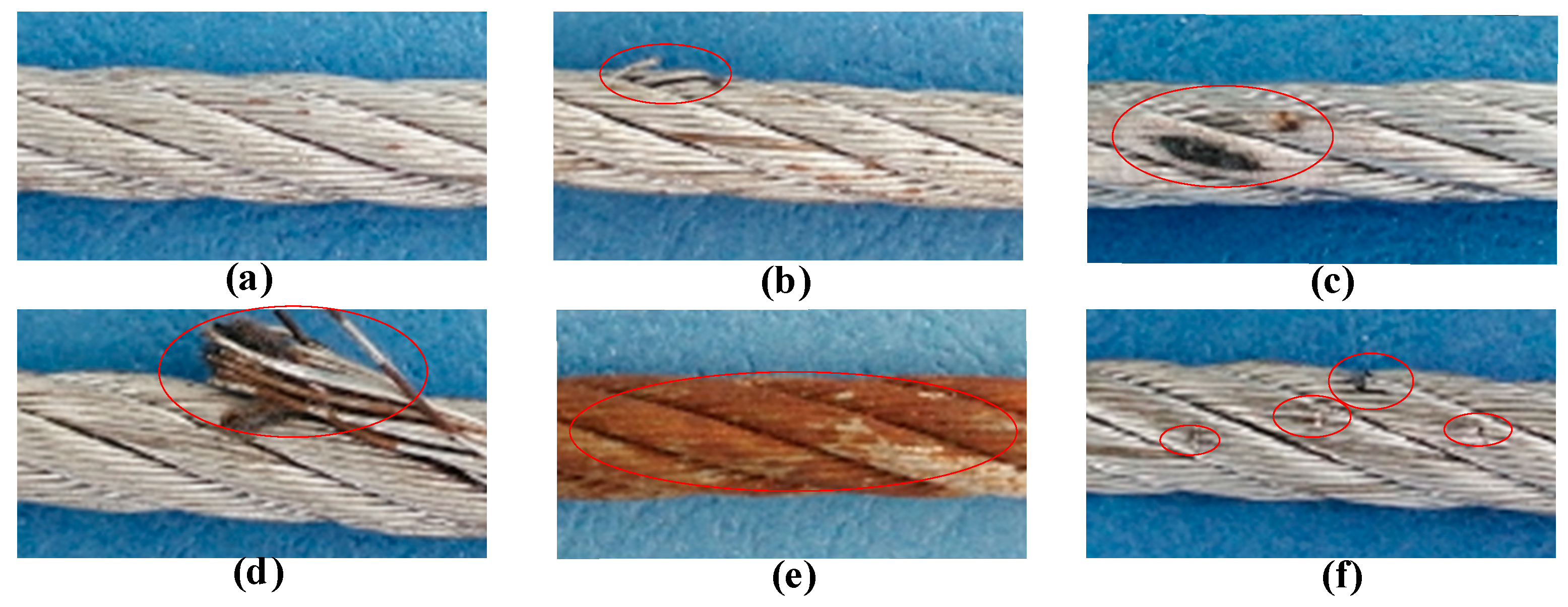
Image of broken wires (infrared image, magnetic image, and photo of the tested wire part from left to right): (a) one broken wire; (b) two broken wires; (c) three broken wires; (d) four broken wires; (e) five broken wires; (f) seven broken wires.
The defect images from UME and infrared have high dimension, which will reduce the speed of classification. Redundancy between features can also be disastrous for networks. Thus, it is necessary to employ proper features to implement recognition. Tan and Zhang [33] had proven that average contrast, third-order moment, conformance, and entropy were more sensitive than other texture features and odd order invariant moments were more sensitive than other moments. Thus, in this experiment, a part of statistical texture features and odd order invariant moments from the magnetic images and the color moments and areas from the infrared images are selected.
When completing classification via magnetic features only, a part of statistical texture features and odd order invariant moments is adopted. If the magnetic and infrared information are combined to classify the broken wires, we added the color moments and area of infrared images as features.3.3.2. Fusion Based on KELM
Infrared data is closer to the actual damage pattern than magnetic data and provides more color information; however, different sizes of same broken wires may lead to low accuracy. Magnetic data with the same broken wires has similar visual image. Thus, the combination of the two methods can supply more information for the damage and improve the classification accuracy.
Through Table 1, it is demonstrated that as the number of test samples increases, the quality of the results gets better. When selecting model 2 to present the speed of classifiers, the result of fusion speed is as shown in Table 2. In Table 1, the fusion results of RBF and KELM are better than BP and KNN. Meanwhile, fusion speed of KELM shown in Table 2 is the best. Thus, through analyzing the result in Tables 1 and 2, it is obvious that KELM is reliable. The research for the performance of recognition algorithms and classification results will be presented in the next section.
In this part, the classification results are presented using different recognition algorithms. KELM has advantages of high running speed and good generalization, we adopted it to implement the recognition of 6 classes of broken wires. In this section, the defects by magnetic information, infrared data, and combination of the magnetic and infrared information are classified, respectively, which proves that the information fusion is more effective. For KELM, the penalty coefficient C and kernel parameter are adjusted from the set and . The KELM network is trained by a set of 139 randomly selected specimens, and the others are the testing samples.
For UME, the average of two error accuracy of 20 random train/test splits with different parameters are reported in Table 3. Different parameters will lead to different identification accuracy. When and , the recognition accuracy rate is the highest; however, the average training accuracy is only 82.3%. The average training accuracy reaches 96.7% and the recognition accuracy is 91.2% when and . Table 3 presents the average of two error recognition accuracy of 20 randomly generated train/test splits based on the fusion of magnetic and infrared. When the training accuracy is higher than 90%, the highest accuracy is 98.4%.
Figure 17 shows the absolute error distribution of one group testing result when and . The training accuracy of two methods are all higher than 90%. When the magnetic information only exists in the network, the maximum error is 5. When the infrared information only exists in the network, the maximum error is also 5. And the most errors are concentrated in one and two broken wires. However, when the fusion features contain in the network, the maximum error is 2, and the recognition accuracy is higher. It is obvious that there are fewer errors using the fused features than that adopting magnetic features only and infrared only. Therefore, these testing results demonstrate that the fusion of magnetic and infrared not only is feasible but also can improve the recognition accuracy of broken wires.
Several recognition algorithms are applied to the MFL data: BP neural network [28, 29, 32], RBF algorithm [27], and KNN algorithm [30]. The data for recognition is the same as that used in the KELM network. Tables 4–6 show the recognition results for each method when the limiting error is 2 wires.
From Tables 3–6, it is obvious that the fused data yielded much better classification results than magnetic data. In this paper, neural networks are considered reliable when the training accuracy is higher than 90%. (Note that KNN has no training process and the algorithm finds samples in the training set closest to the test sample based on a distance measurement [30, 45].) Therefore, the highest recognition rates are presented in Table 7. Table 7 presents the best results of four classifiers using only magnetic data, infrared data, and fused data. It is obvious that the result for fused data is higher than magnetic and infrared.
The research promotes recognition rate of broken wires and makes contributions to estimating the residual lifetime of wire rope. The two information can overcome the loss of small defects in magnetic signal noise reduction. The system we utilized have good performance facing the defects at the exterior of the rope. However, the thermal infrared acquisition system needs to be perfected to realize the image information acquisition of the whole wire rope. Furthermore, we have not been able to create defects inside of the wire rope. We will simulate the situation when the defect is inside the wire rope through analysis in future work. Meanwhile, efficient noise reduction algorithm is also one of the focuses of future research.
Maintain a record for each rope that includes the date of inspection, type of inspection, the name of the person who performed the inspection, and inspection results.
Use the "rag-and-visual" method to check for external damage. Grab the rope lightly and with a rag or cotton cloth, move the rag slowly along the wire. Broken wires will often "porcupine" (stick out) and these broken wires will snag on the rag. If the cloth catches, stop and visually assess the rope. It is also important to visually inspect the wire (without a rag). Some wire breaks will not porcupine.
Measure the rope diameter. Compare the rope diameter measurements with the original diameter. If the measurements are different, this change indicates external and/or internal rope damage.
Visually check for abrasions, corrosion, pitting, and lubrication inside the rope. Insert a marlin spike beneath two strands and rotate to lift strands and open rope.
Assess the condition of the rope at the section showing the most wear. Discard a wire rope if you find any of the following conditions:In running ropes (wound on drums or passed over sheaves), 6 or more broken wires in one rope lay length; 3 or more broken wires in one strand in one rope lay. (One rope lay is the distance necessary to complete one turn of the strand around the diameter of the rope.)
Corrosion from lack of lubrication and exposure to heat or moisture (e.g., wire rope shows signs of pitting). A fibre core rope will dry out and break at temperatures above 120°C (250°F).
Kinks from the improper installation of new rope, the sudden release of a load or knots made to shorten a rope. A kink cannot be removed without creating a weak section. Discarding kinked rope is best.


 8613371530291