
wire rope bridge design price

Bridges are the best way to connect two tree house platforms to each other. We also build bridges from the ground up to a tree house or from a back deck out to a tree house. Construction of a short rope bridge is a reasonably simple task. However, some suspension bridges span great distances and require more serious design & construction practices.
If you would like to build your own cable bridge like the ones we build, then check out the treehouse bridge kits at Treehouse Supplies. They do require assembly, but instructions and support are included.
The costs for small bridges in between tree house platforms normally range from $3000 to $20,000. The costs for large cable bridges can be between $60,000 and $500,000. The big price ranges are because the length and site specific factors can make the cost vary greatly. Remember that large bridges such as canyon crossings will require site visits, careful measurements, engineering, and large towers and/or footings to ensure safety.
Bridges can be made from different combinations of materials such as rope, cable, chain, steel, and wood. The choice is made based on the required strength, the intended use of the bridge, and the aesthetic preference of the owner or designer. Our preferred method is to use cable for the main suspension, and then netting on the sides to prevent little bridge visitors from falling off as they traverse. On shorter bridges, we can consider alternate methods such as a rope only bridge. Larger, more serious cable suspension bridges may require concrete footings, towers, and stiffer walking surfaces than wood planks.
Trees are very strong, but they are not accustomed to resisting large lateral forces. They can support a great deal of weight, especially near to the ground. The trouble is, with larger suspension bridges, the long upper cables are attached high in the tree and pull not straight down but inward to the center of the bridge. This is quite unnatural and with medium to large bridges, the limits of the trees can be exceeded even when guy wires are attached appropriately. In such cases, towers are erected to support each side of the bridge. These towers must be designed by qualified engineers in order to make sure that appropriate materials are custom fabricated for each bridge project.
To get started, we normally need to see the site, take measurements, and tell you what we can and can’t do for you, and what it will cost. We do charge for such site feasibility studies, and the fees are based on our travel costs and time spent on the visit. If you would like to get a free estimate before paying for the feasibility study, then please get us some preliminary information such as the rough topography, pictures, the length, and any other site specific factors that will help us give you an estimate in the form of an expected price range. Our estimates for rope, cable, or suspension bridges that are of reasonable length between two appropriate sized trees are generally pretty accurate, but for larger bridges, we normally can’t commit to the final price until we see it.
I’ve had several inquiries lately about the cost of building my bridge. I left prices out of my book because it depends on the current market and what is available in your local supply market. But here is what it would cost today to build this bridge near Eugene, Oregon.
*** Cable Locking System: *** Depends on where you have them made. Here they are about $12.50 each: 18 CLS pcs. per 1/2 bridge length @ $12.50 ea. $225.00
Be sure to check out my new book, Building a Small Cable Suspension Bridge. There is a link to purchase it here: http://www.wildcatman.com. There is also a link there to contact me.

Longer span Rope Bridges can be anchored across rivers, lakes and even canyons. Perfect for going tree-to-tree in woodlands, for Tree-Top Walkways and for adding that extra air of excitement in gardens, woodlands, resorts and adventure parks.
Short span Rope Bridges are perfect for treehouses and the ideal go-between when adding platforms or play ‘islands’. Adds real adventure and fantasy plus a playful connection to our whole world of play.
Our Log Rope Bridges are a perfect solution where a treehouse adventure starts from the lawn or woodland floor, leading upwards to a treehouse or platform. Our Log Rope Bridges make an awesome treehouse or platform entrance.
Suspended Rope Bridges can offer a perfect solution when looking to cross over large areas, such as rivers, lakes, ponds and even canyons. They also provide an exciting and flexible design option in Adventure Parks.
We work from anchor points established at each end, using either a zero-impact certified and proprietary ground buried anchor system or suitable ground buried concrete ‘pads’ with integrated structural anchor plates, that are designed and fabricated at our workshop. Typically, if suitable trees are available, we can ‘anchor’ to trees at each end of the Rope Bridge using tree-friendly webbing slings or rope soft-shackles.
In every project, the anchor points can always run longer than the actual Rope Bridge span, allowing us to also integrate ground-based deck platforms (with balustrades if necessary) at each end. This not only creates a truly impressive looking ‘start’ and ‘finish’ to the Rope Bridge, it also helps us to negotiate the height of the Rope Bridge above water, should there be any relevant issues with flood forecasts.
The most common lengths of Rope Bridges we have installed has been anywhere from 5m up to 45m. But if you’re thinking of something on a grander scale, that’s not a problem at all.
We have designed and installed 45m long Rope Bridges that span across rivers and canyons, and on one project, even installed a Rope Bridge directly into granite boulders when the availability of ground anchors or nearby trees was not an option. Whatever your wish our teams at Treehouse Life will always look for a way to make it work.
As ever, with Rope Bridge design and build, the key to structural integrity and design success is very much down to the lay of the land at the proposed location. While we can initially work from location photos to advise and consult regarding your Rope Bridge options, we do offer an on-site visit consultancy so that we can to discuss all opportunities.
Structurally, suspended Rope Bridges work from anchor-to-anchor using structural steel cables or ropes with all elements suspended inbound on the structural lines, including the round timber uprights at each end that are required for the rope-work balustrades.
This is what we call a ‘floating Rope Bridge’ solution, which allows us to work with our own Rope Bridge system in many unique and incredible locations both throughout the UK and around the world.
Our fixed-beam Rope Bridges are a perfect design solution to reach a treehouse or link up multiple platforms or decks. The purpose of the integrated fixed-beam is simply to hold the two ends apart; it typically sits at half-height within the rope balustrades, but can also sit lower or even closer to the upper ‘hand-rail‘.
On this particular Rope Bridge design and installation solution, because the ‘stress-and-strain‘ between the two fixed points is taken up by the fixed-beam, we support the timber walkway treads underneath with ropes that are fixed at each end to a round timber beam.
Structurally perfect and beautiful in design, Fixed-Beam Rope Bridges for treehouses, platforms and decks can add a whole other dimension of fantasy and imaginative play.
With the bridge always sitting level end-to-end, it is possible for us to increase (or decrease) the overall height by installing an additional step up and/or down at either end (usually 300mm).
Although this is a fully integrated Rope Bridge design and installation, there is however a limit to the distance the bridge can actually cover. This is determined by the length of the actual fixed- beams we use; a 3m span or less works perfectly, although there are some other excellent options if a span of up to 6m long is required.
Overall, the structural integrity is always going to be heavily dependent upon what is available at each end of the bridge – so our advice (based on years of experience) would always be for a Rope Bridge to be integral to an overall design rather than being an add-on after everything else has been built.
Include some Climbing Walls, Zip Wires and Fireman’s Poles as part of your child’s treehouse world and you will create the ultimate adventure and fantasy land and a playful connection to a whole world of possibilities – the perfect setup for every family back garden or school playground.
Our Log Rope Bridges are a perfect solution for every magical journey, starting each new treehouse adventure right from the middle of the lawn or woodland floor, and leading it all the way upwards to a treehouse or platform.
What better entrance could there be, than feeling those butterflies of excitement and the rush of make-believe from the moment you place your foot on that very first log and then cross the Rope Bridge into a faraway kingdom or land.
When incorporating a change in height into our designs, using flat Rope Bridge ‘slats’ simply wouldn’t do the job; too much of a gradient and the bridge would literally turn into a slide! The answer is in the use of round timber logs set inbound on ropes or steel cables, providing the intrepid climber with suitable ‘steps’ whilst they hold onto the rope balustrades.
Typically, with Rope Bridges up to approximately 4.8m in length (which is ideal for a Rope Bridge entrance), we integrate a fixed-beam into the Rope Bridge to hold the two ends apart.
The route up and into a treehouse needs to be exciting and imaginative and very much a part of the play journey itself and this is where the magic begins. Log Rope Bridges offer that perfect – not to mention most adventurous – entrance to any garden or backyard treehouse play-set or platform decks.
Treetop Walkways by Treehouse Life are able to find new pathways up high in the tree canopy. View nature from the branches within touching distance of leaves and wildlife alike. Safe, functional and exciting these bridges are a magical way to enjoy time in the woods.
Awesome Rope Bridge addition for a woodland treehouse project. A beautiful construction that spans across a river, for extra excitement. Beautiful wooden Rope Bridge made of pinewood and natural hemp rope
A selection of Treetop Walkway Bridges by Treehouse Life. These stunning bridges act as large hammocks, perfect for woodland relaxation and fun. Immense enjoyment and excitement for adventurers of all ages. Wonderful adventure play equipment by Treehouse Life.
A stunning collection of professional Rope Bridges accompanied with 4-sided rope ladders. An incredible way to walk around the tree canopy in a safe and exciting way. Brilliant for adding new pathways high in the tree canopy close to nature and wildlife. The hanging V-shaped Hammock Bridges are wonderful for relaxing and laying down in as well as a ton of fun.
School project completed with triple Rope Ladders and a Treetop-Trail Rope Bridge, a brilliant way to encourage active play in the great outdoors getting children to interact with nature.
Scottish adventure park equipped with our Treetop Walkway. Walk around the woodland with ease reaching the tree canopy and wildlife, these bridges are immense fun and make an awesome experience.
With Rope Bridge projects worldwide this is one of a number of projects in Ibiza. Following a site consultation, we set up the whole project to be delivered door-to-door by sea container with our key-skills team from the UK and a local labour team.
Such an incredible Rope Bridge built for the National Trust. Designed and made to cross over an impressive river this bridge is exciting and fun. Giving access to new land across the river this bridge is a great addition to the property. Superb fun, safe and adventurous these bridges bring Indiana Jones to mind. Amazing stuff by Treehouse Life.
Beautiful garden project on the amazing island of Jersey. In a wonderful family garden setting Treehouse Life created a long Rope Bridge spanning across a pond, also an exciting Zip Wire for young adventurers to enjoy.
Aerial adventure course with a Tree Canopy Walkway. Travel through the woods and between trees up high in the canopy. Explore canopy wildlife and nature in a safe and functional Treetop Rope Bridge.
A seriously impressive Rope Bridge built in an amazing rural setting. Spanning across a small ravine and surrounded by an established woodland this is an incredible way to walk within the trees. Built with top-quality materials these bridges are fun and built to last.
A superb gallery showcasing some stunning rope bridges and treetop walkways for an Oxford treehouse project. Nestled in a wonderful woodland this adventure play treehouse hosts many different play options and encourages hours of fun in the great outdoors.
Amazing aerial adventure park, built in surrounding woodlands and nature. With Treetop Walkway bridges, Rope Ladders, Zip Wires and Tree Swings this play area hosts a wealth of exciting play equipment.
A Tree-top Walkway taking an adventure journey through the woodland and the opportunity to Zip Wire across a lake and bring the button seat back for the next go.
Great photos of Treehouses fitted with Treetop Walkway Rope Bridges. The best way to experience nature up high in the canopy. Get a sense of adventure and exploration using these safe and exciting rope bridges.
A stunning Rope Bridge built for the National Trust. At their amazing Sheffield Park Estate, this bridge opens new pathways to woodlands that were previously unreachable. It is an exciting way to walk around the estate and definitely gets adrenaline going. Functional, safe and fun these bridges are superb and amazing to look at.
The UK’s longest and highest treetop walkway at Groombridge Place in Kent. Walking in a deep within a 2.1m ‘V’ shaped safety netting and tree-to-tree in a free-flowing, suspended and ‘floating’ soft ‘hammock-style’ experience. Wild deer adventuring in the woods underneath whilst in a beautifully relaxed and quiet place to observe nature.
Incredible suspended tree canopy platform. The perfect way to view the surrounding woodland from a high vantage point. Use the treetop walkway bridges to reach the wooden deck and look out to see birds and wildlife. Built within an RSPB nature reserve you can spot, bats, rare birds and other woodland creatures.
“I would highly recommend Treehouse Life. Their design for a play area for my children was well thought out and fitted perfectly into the space we had. They were quick to install and the quality of the materials and the overall build is exceptional. My children love playing there, so in short it was well worth it.”
“Treehouse Life Ltd created a stunning Treehouse and Rope Bridge for our garden project in Lancashire, The Old Vicarage. The structure is a timeless addition to the garden and is loved by the family. As a garden feature, a destination and a source of play it is just perfect. We have had many enquiries and admiring comments regarding the Treehouse, in fact it features in some of our most popular photos on Houzz. The project was a finalist at the Northern Design Awards in 2015. We would highly recommend Paul and his team to any client and hope very much to join forces in the near future.”
"We hired Paul and his team to build a Rope Bridge in the Seychelles on the site of a Spa we are constructing for a 5 star resort. We are very pleased with the efficient quality service and we were provided with and the end result looks fantastic."
Established in the year1992, we, Apicon Real Infra Pvt. Ltd. (M/s Aquatic Pumps Industries) an ISO 9001 : 2015 certified company engaged in fabrication & installation of suspension bridge, wireless tower, industrial pressure vessels, storage tanks, industrial storage tanks, mobile storage tanks & tankers, dam/canal gates and a host of other metal fabricated products. Since our establishment, we are excelling towards becoming global suppliers of our range of products & services. From designing & engineering to installation and post sales services, we endeavor to exceed our client"s expectations by offering them customized services. We constantly upgrade our infrastructure so as to fabricate superior quality product at most competitive prices. We export our products in all over the world.
Earlier, our company was engaged in offering submersible pumps but since 1992 we are exclusively involved in fabrication work. As a committed manufacturer, we ensure that all our fabrications are manufactured with accuracy and complete attention is laid to every minute detail/ specifications that is required to be incorporated. Competent technical teams with wide industry expertise back all our operations. They support us to design, develop & deliver according to client"s specifications. Our rich exposure to various types of clients (from diverse segments/ industries) has always been a guiding factor and this steers us towards measures success.
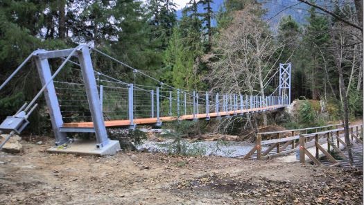
We built this bridge and wrote a “how we did it” book about the process a few years ago. I thought it would be fun to share the basics of this design as an Instructable for people who have enough skill to be able to take the information and work with it. And as we do in our book, we recommend having your specific design approved by an engineer just to be on the safe side.
Here is our design for an 80’ long walking bridge that spans our creek and is set back far enough for a serious flood. The challenge was to do as much as possible without the need of machinery or swimming. Even if your creek isn’t that wide, consider flood stage and go from there.
Dead men are a vital part of this design (the foundation in the ground). Engineered based on the load, they were were buried and secured before the suspension cables were brought in.
The stringers were also spaced to deal with harmonic resonance. Though keep in mind, it’s a suspension bridge and it will move when you walk on it. Whee!
This bridge has been our access across the creek to get to our spring for many years, and is holding up great through several major floods. A couple of trees have hit it, but it wasn’t phased. We recently adjusted the turnbuckles on the dead men cables to pull up the slack in the deck from tree hits.
Note that all photos and illustrations are from our book, Building a Small Cable Suspension Bridge with the Cable Locking System. The book is easily found on Amazon.com if you look it up, and our blog with more info is wildcatman.wordpress.com. Hopefully this is enough information to get you inspired!
Almost ten years ago we posted a materials list with prices for our 80" bridge. You can find that here, although obviously the prices will be outdated: https://wildcatman.wordpress.com/2013/04/18/cost-t...
We suspect a public park would want a bridge that was much more solid than this style, but "millions $" sounds pretty steep! Check out the designs here: https://www.aia.org/showcases/6121109-forest-park-...
The main cables are 1/2” and the suspenders are 3/16” galvanized cable. A complete materials list is here: https://wildcatman.wordpress.com/2013/04/18/cost-to-build-a-small-cable-suspension-bridge/0
im trying to make a suspension mini bridge for school to have a competition to see which bridge can holod the most weight how do i make a stable good suspension bridge?
Thanks for asking, and sorry, no. I could design a bridge like this for us but not for someone else, since I am not a licensed engineer. Good luck! Maybe check with Bridges to Prosperity and see if they"ll share a design with you?0
The main cables are 1/2” and the suspenders are 3/16” galvanized cable. A complete materials list is here: https://wildcatman.wordpress.com/2013/04/18/cost-to-build-a-small-cable-suspension-bridge/0
I"ve read the book and loved it. Thank you for putting this info together. It"s really motivating for people who"d like to start a similar undertaking. My question: is the suspended bridge style suitable for bridges with a grade, with two ends at different altitudes? If so, what kind of adjustments should be made to the project to account for the grade?
Thanks for the compliments on our book, and for your question. I don’t know what kind of altitude changes you’re talking about, but if they are minor, then it shouldn’t make any real difference. You can adjust where the bridge deck levels to the posts and then build a ramp or stairs to get up to it from the low side.
If you’re talking about a slope on the bridge deck (because cutting the high grade or ramping up to the low side isn’t an option) then the functionality of the bridge using the parts I employed won’t really be compromised because it’s a small bridge not meant for heavy loads. That said, I would however be concerned about safety on a bridge that isn’t level - not only the precarious feeling it could illicit in the person walking on it, it could be slippery.ReplyUpvote
Bethlehem Structural Strand is an arrangement of wires laid helically around a center wire to produce a symmetrical cross section. Structural strand is used as a load-carrying tension member where great flexibility and bending are not major requirements. For any given diameter, wire strand is the least flexible of steel cables. Structural strand provides a high strength-to-weight ratio, a high modulus of elasticity and a small diameter-per-unit strength. These are the features that permit strand to adapt so successfully to structural applications. WW manufactures Bethlehem Structural Strand to meet ASTM Specification A586, and we have the capability to manufacture strand as large as 5-1/2"diameter. Refer to Table 1 for structural strand data.
Bethlehem Structural Wire Rope consists of six strands made from zinc-coated wire with strands laid helically around a core, such as another strand or smaller wire rope. Structural wire rope provides greater flexibility when compared with coarse strand constructions and is generally the structural cable of choice where bending ability is an important requirement, such as forming flemish eye ends (drop terminals). WW manufactures Bethlehem Structural Wire Rope to meet ASTM Specification A603, and has the capability to manufacture wire rope as large as 7"diameter. Refer to Table 2 for Bethlehem Structural Wire Rope data.
Wirerope Works, Inc. offers SS-265™, a high strength structural strand designed specifically for use in tower applications. Compared with standard structural strand, SS-265 offers an increase in minimum breaking force of 15% above the values for strand manufactured to specification ASTM-A586. Using SS-265 also offers these advantages:
Reduced Structural Strand Diameter—Now that designers can utilize a smaller diameter strand for the guying system, SS-265 offers a lower cost per foot, allowing the user to cut valuable dollars from the cost of a project.
For users who opt to use SS-265 without downsizing the diameter of the strand, other benefits apply. For example, using a 2-inch diameter as an example, the minimum breaking force increases from 245 tons to SS-265’s 282 tons. The higher strength results in an increased design factor of the guying system. SS-265 also may be used in other applications where structural strand manufactured to ASTM-A586 is utilized. Please contact your WW regional sales manager or customer service representative for further information.
To ensure quality of all Bethlehem Wire Rope and Strand products, WW utilizes Statistical Process Controls (SPC). In doing so, we are able to test and certify the following:
Cable-stayed bridges are a subcategory of suspended structures. A cable-stayed bridge is similar to a suspension bridge in having towers and a deck-girder supported by cables; however, its diagonal cables transfer the vertical loads from the deck directly to the towers. Thus, the main deck-girder of a cable-stayed bridge works like a continuous beam on cable supports (more flexible than pier supports) with additional compression force throughout the deck. A cable-stayed bridge is also a prestressed system as its cable-stays are additionally tensioned to counterbalance a significant part of the vertical loads on the main deck-girder.
The Strömsund Bridge in Sweden, completed in 1956 with a 182-meter (597-foot) main span, is considered the first modern cable-stayed bridge. For the following 65 years, cable-stayed bridges have seen a dramatic increase in both the number of new structures and in long-span achievements. By 1995, there were only 3 cable-stayed bridges with spans over 500 meters (1,640 feet); 25 years later, there are already 67 cable-stayed bridges with spans over 500 meters (including three over 1,000 meters or 3,280 feet). Another 29 with spans over 500 meters, with some over 800 meters (2,624 feet), are currently under construction.
The efficient range of cable-stayed bridges is moving towards even longer spans. There is no other bridge structural system exhibiting such rapid development. Most cable-stayed bridges are visually beautiful, and some are among the most impressive of engineering achievements.
The idea for the cable-stayed system was perhaps inspired by the drawbridges of medieval castles and the rope-braced masts of tall ships. The very first documented image of a cable-stayed bridge appears in the Machinae Novae, a book by Fausto Veranzio published in 1615.
Predecessors for modern cable-stayed bridges appeared in the 19th century in the form of different hybrid combinations of suspension systems with additional diagonal straight cables, as in the case of the Albert Bridge, UK (1873). The best known of these hybrid structures is the Brooklyn Bridge, New York, 1883, with a 486-meter main span (1,594 feet), for which John Roebling used diagonal cables for stiffening the structure.
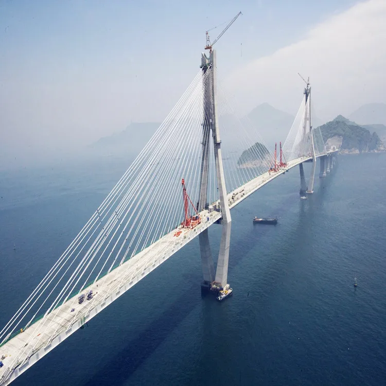
In the 1960s and 1970s, the system was developed further to replace many of the bridges destroyed in Germany during World War II. In this period, the system was also used for roof structures requiring long, column-free spaces in buildings. Initially, cable-stayed structures were used for bridge spans of 60 to 250 meters (196 to 820 feet) but today they span much longer distances and are the only system that challenges suspension bridges in super-long spans. Their spans grew to 302 meters (990 feet) in 1959 with the Severin Bridge (Germany), to 404 meters (1,325 feet) in 1974 with the Saint Nazaire Bridge (France), and 856 meters (2,808 feet) in 1995 with Michel Virlogeux’s Normandy Bridge (France). Today, the Russky Island Bridge (Russia) has the longest span of this system, 1,104 meters (3,622 feet) achieved in 2012 (Figure 1).
In the United States, we can mention the second Sunshine Skyway Bridge with a span 366-meter (1,200 feet) in 1987 (Florida), the Dames Point Bridge with a 396-meter span (1,300-foot) in Florida, and the Arthur Ravenel Bridge with a 471-meter span (1,545-foot) in 2005 (South Carolina).
The main elements of a cable-stayed bridge are towers or pylons, deck girder(s), cable-stays, anchorages, and foundations. Tower and pylon are interchangeable terms; lighter, slender towers are often called pylons. The classic cable-stayed bridges are symmetric with one central span, two side spans, and two towers; such are most cable-stayed bridges with spans above 600 meters. The back-up cables may extend over several side spans.
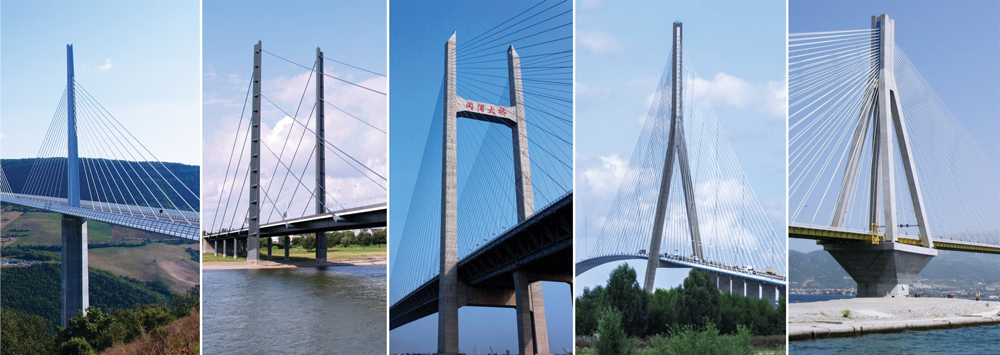
Asymmetric cable-stayed bridges have one main span and one side span, with a single tower. Multiple-span cable-stayed bridges have two or more (usually equal) main spans. Several examples are shown in Figure 2.
Some sub-divisions are used for cable-stayed bridges: extradosed, under-spanned (under-deck), cradle, inverted Fink truss, and tensegrity. The cables at the towers can be arranged in parallel (harp), fan, star, or mixed configuration. Various structural solutions are used for the towers: single pylons, double-leg portals (vertical, slightly angled, free-standing, or interconnected as a portal frame, with “A,” “H,” “Y,” or inverted “Y” shaped arches).
For deck-girders: beams of prestressed concrete or steel, box girders of prestressed concrete or steel, similar to those in modern suspension bridges;
For cables: high-strength steel wires, usually 270 grade (270 ksi, or 1,860 MPa), built from 7-wire, ⅜-inch (9.5 millimeters) strands per ASTM A886, other higher-grade steel wires, carbon fiber-reinforced polymers (CFRP), or composites. Prestressed concrete has been used in the past, but should be avoided as it has been proven unsafe on some failures such as the Morandi Bridge;
For long-span bridges, foundations on soft soils, or for bridges in high seismic areas, it is preferable to use predominantly steel structures to reduce the self-weight and the related earthquake forces.
The most important part of bridge design is the overall concept for the structure and its elements: the selection of the appropriate structural system for the bridge considering its specific function, site location, and required spans. A well-selected concept determines the efficiency and economy of the bridge, saves materials, cost, and construction time. Good design concepts minimize problems and future difficulties both in the design office and on the construction site.
For the design of early cable-stayed bridges, engineers used a relatively small number of cables. After acquiring more experience and with the introduction of structural design software, engineers were able to use a larger number of cable stays, reducing the demand on the deck girder and leading to greater efficiency and longer spans.
The basics of cable-stayed bridge design are as follows: the vertical loads on the deck are supported by diagonal cable stays that transfer these loads to the towers. At the tower, the horizontal components of the cables from the main span are in balance with those from the side/adjacent spans. The towers support and transfer the vertical load to the foundations. Similarly, the cumulative compression horizontal components of the loads from the main span are in balance with the compression load components of the side spans. Therefore, the entire bridge system is in balance with predominant compression forces in the towers and the deck system, and with tension forces in the cable stays. The system is self-balanced, provided that all elements are designed correctly to sustain the maximum demand from the highest possible combination of loads.
The challenge for the design engineer is to select an appropriate combination of the multiple possible variations of towers, cable-stay arrangements, and deck systems. Like all suspended structures, cable-stayed bridges are sensitive to deformations and it is necessary to check the deformed condition of the system for all load combinations, including those during the different phases of construction.
Today’s structural design software greatly assists engineers in the calculation of cable-stayed bridges. After choosing the main parameters of the system, it is essential to establish the start-up dimensions and sections of the deck-girder, cables, and towers. A simple design approach will help in setting up these dimensions.
For a start, the designer can use a substitution simply-supported beam for determining the approximate bending moments for the main span deck-girder. The upward cable-stays pretension can offset most of the moments from permanent loads on the deck. This is achieved with additional tensioning of the cables after erecting the main elements to counteract permanent loads, resulting in minimal vertical bending in the deck-girder. The cables should be additionally tensioned to counteract 50% of the combined temporary downward loads (live loads, wind, snow, ice, and earthquake). This way, the working bending moments of the deck-girder will vary during operation approximately between 50% of the positive moments (from the worst temporary load combination) to 50% of the negative moments from temporary loads. This “first step” determines the design moments for the main span deck-girder. The compression in the deck-girder due to the horizontal components of cable stays forces is the cumulative sum of these components, approximately 55 to 65% of the total vertical loads on the main span depending on the span, the number of cables, and the height of cable connections at the tower. The cumulative compression force (ΣPc) in the deck-girder is equal to the sum of all compression forces Pci at cable connections (Figure 4) at the deck: the tension cable force Pcable = Pv/sin α,
These calculations will allow the designer to establish the initial design dimensions for the cables, deck-girder, and tower to be used in the computer model for further adjustments and refinements of the system. The deck-girder has to be designed for the compression and bending from the cable-stay system and the typical bridge deck design for vertical dead and live loads. The initial approach described above will help to achieve the desired final goal faster.
Cable-stayed bridges are efficient in cost, materials, and construction time. They have better efficiency than other bridge systems, with the only competitor being suspension systems, while allowing for more straightforward construction methods. An additional advantage of cable-stayed bridges is their larger efficient span range from 100-meter spans (328 feet) to over 1,000-meter spans (3,280 feet).
The multitude of possibilities of the system provide engineers and architects with many design options. The “mid-long range” structures allow more creativity, originality, and possibilities for innovative work. A cable-stayed bridge does not need to be extravagant. The most straightforward bridge with a “sincere” structure is often the best and is usually elegant and attractive.
Cable-stayed bridges have a combination of elegance, slenderness, and a feeling of robustness. The national infrastructure’s demand for more bridges requires the priority of efficiency and economy.
Like all other bridge systems, cable-stayed bridges are continuously improved based on the development of high-strength materials and new construction technologies. More valuable for engineers are the modifications of established structural systems and newer sub-systems. In addition to the increased number of cable-stayed bridges with longer spans (above 600 meters or approximately 2,000 feet), there is increasing use of the system for pedestrian bridges. The lower loads and shorter spans allow engineers to explore new approaches, transforming the building of these bridges into a testing lab for innovation. As such, we may consider the extradosed, under-spanned, and inverted Fink truss sub-bridge systems, all oriented to improved efficiency.
One area of further development is the pursuit of combinations/hybrids of cable-stayed and suspension bridge systems for achieving super-long spans. The idea is to reduce the suspension span length by moving the suspension support points inward along the span. This not only reduces the suspension span length but the required tower height as well while allowing a longer clear span. This is obtained with “cable-stay cantilevered alternatives” at the bridge towers, adding “on-deck” cable-stayed pylons (Figure 5). With 500-meter (1,640-foot) cantilevers and cable-stayed “on-deck” pylons used on each side of a total clear span of 3,000 meters (9,842 feet), the suspension part is reduced to 2,000 meters (6,561 feet). Such reduction would allow using main suspension cables of the size and type of those already used in bridges, like the Akashi-Kaikyo at 1991 meters (6,532 feet), for a much longer main span.
Based on current technical progress and fast development, cable-stayed bridges may reach spans 2,400 to 2,600 meters (7,600 to 8,500 feet) in a short while; such design will require towers about 500 to 570 meters tall (1640 feet to 1,870 feet), something achievable, considering already completed skyscraper structures. This will extend the efficiency range for cable-stayed bridges to very long spans above 2,000 meters (6,561 feet). A hybrid cable-stayed-and-suspension system would make possible even longer spans of up to 3,000 to 3,400 meters (9,842 to over 11,000 feet), incorporating a “pure” suspension bridge of “only” 2,200 to 2,400 meters (7,218 to 7,874 feet).
Based on the efficiency and advantages of cable-stayed structures, American engineers and transportation agencies should consider more cable-stayed bridges when planning new projects. Greater use of cable-stayed bridges may upgrade the infrastructure with these efficient, faster built, and elegant structures. Making cable-stayed bridges more popular may also help our bridge engineering profession regain its position of leadership in the design and construction of long-span bridges.■
Structural wire rope cables have played a major role in the engineering and architecture of many large structures and are widely used on projects involving bridges, vessels, stadiums and glass facade/membrane buildings to name a few. Using steel cables in the design of such projects has proved more cost effective than solely using raw materials such as Iron or concrete and is now very much the preferred choice within the construction and engineering sector.
The starting point for FATZER products is high-tensile steel wire. Fabricated into steel wire ropes, it enables architects, engineers and contractors to create technically sophisticated rope architecture.
FATZER manufacture a wide range of rope diameters, suitable for use on the most complex of projects. The performance parameters of all products are monitored and confirmed by independent test bodies.
It goes without saying that steel wire ropes must meet the highest safety requirements. What sets them apart though, is the way they provide freedom for aesthetically creative design. It is the elegant HYEND series of end connections, in particular, which turns these technical products into true “design objects”.
Spiral strand and fully locked coil ropes are manufactured in Switzerland in FATZER"s own factory. This covers the whole process including stranding, pre-stretching, marking and in some cases socketing. Handling customised product solutions is a challenge we tackle on a daily basis. In all cases rope assemblies arrive on site ready for installation.
All materials are fully certified and has full traceability in line with our ISO9001 procedures. The most common constructions of wire rope used for structural purposes are: Spiral strand ropes and fully locked coil rope (EN 1993-1-11:2006). All ropes are available with HYEND fittings to guarantee the best quality and safety standard (EN 13411-4).
SWR have the capacity to design and manufacture these assemblies, and can provide structural advice on load ratings and fixing terminals should this be required. Both galvanised and stainless steel can be used depending on the location and specification of the project.

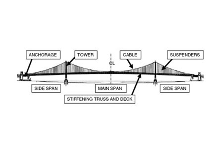
A suspension bridge is referred to a type bridge supported by cables. This type of bridge has been with mankind since ancient times. Today’s large and magnificent suspension bridges were made possible through the establishment of structural analysis methods, material developments, construction methods, and computer technology developments. Suspension bridges are one of the most beautiful special bridges, and are considered one of the types of bridges many structural engineers dream to design.
The classification according to the girder type is based on the degree of freedom of the suspension bridge girder. The 3 hinged stiffening girder type is interpreted as a statically determinate structure, and the 2 hinged stiffening girder and continuous girder type are interpreted as statically indeterminate structures. Continuous girder types are used when external loads are large, such as in road rail bridges, because they increase the stiffness of suspension bridges and reduce the amount of deflection.
An earth-anchored suspension bridge is a type of bridge in which the main cables are anchored on large concrete blocks, or on the ground, located at the ends of the bridge. External loads applied to suspension bridges are transferred to the suspenders main cables anchorages & pylons and finally to the ground.
A self-anchored suspension bridge is a type of bridge supported by the main cables anchored to the girder. External loads applied to suspension bridges are transferred to the girder through the suspenders main cables pylons and anchorage inside the girder. Therefore, unlike earth-anchored types, girders behave as bending and compression members.
Suspenders/Hangers of suspension bridges are usually used with vertical suspenders, and diagonal suspenders can be used to increase the damping on bridges. However, an evaluation of slacking and early fatigue due to the large tensile forces is required. In order to take advantage of cable-stayed bridges and suspension bridges, a hybrid bridge system, in which a cable-stayed system and suspension system are used together, can be implemented.
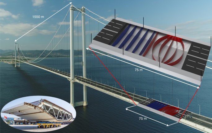
Stiffening girders of suspension bridges are longitudinal structures that support or distribute vehicle loads. Furthermore, since the stiffening girders are supported by cables, aerodynamic stability is required. In the past, I-girders were mostly used for stiffening girders, but later they were developed into truss structures due to aerodynamic stability problems, and most recently been developed into box-shape cross-sections.
Truss girders are proposed for stiffening girders because plate I-girders are disadvantageous with regards to aerodynamic stability. One example in which plate I-girders were used is the Tacoma Narrows Bridge, which is famous for its collapse due to aerodynamic instability. Truss girders can increase the torsional stiffness of suspension bridges by raising the vertical height of the girder and installing horizontal lower bracings. Furthermore, the top and bottom layers of the girder can be used by taking advantage of the height. However, truss girders have large drag due to their heavy weight and long span.
As bridges get longer, it is necessary to secure the torsional stiffness of girders in order to resist aerodynamic loads. This means that it is important to optimize the shape of girders in order to increase the limit wind speed that causes the girder to flutter. Multi-box girders are girder types that secure aerodynamic stability in modern long bridges. Multi-box girders are low in height and light in weight, which reduces the size of cables, pylons/towers, and anchorages, leading to a much economical bridge design.
The main cables used in suspension bridges are tension members, such as ropes, wires, chains, etc., that cannot resists bending or compression, and can only support axial tension. In general, tensile strength of 1,600 ~ 1,800MPa is used for the main cables, but recently, cable steel wires for bridges with tensile strength of 2,200MPa have been developed. Since parallel cables have greater strength than structural steel, the cross-sectional area of the cables is reduced, and thus, secondary stresses, manufacturing errors, and the amount of main cables are significantly reduced.
Cable construction method is mainly divided into Air Spinning method (hereinafter referred to as AS method) and Prefabricated Wire Strand (hereinafter referred to as PWS method).
The AS method uses the cable Hauling system to construct cables in wire units. Wires are formed in strand units at the construction site and constructed as main cables. This method has the advantage of reducing the size of the anchorages. However, wires are sensitive to wind loads and the construction period is longer than wires constructed using the PWS method.
Suspenders are cables that connect the main cables to the girders. There are two main types of suspenders: Center Fit Rope Cores (CFRC) and Parallel Wire Strands (PWS). The CFRC hanger (suspender) system is a method of placing high-strength galvanized steel wires twisted in a spiral shape on top of the band of the main cable and fixing the bearing plate at the saddle-type reinforced girder hanger anchorage. The PWS hanger system is a method of pin-anchoring high-strength galvanized steel wires that are tied together parallelly, forming a hanger rope that is covered by Polyethylene, to the cable band sides and the reinforcing girder sides, respectively.
Special types of suspenders are located at the center of any suspension bridge. These are used to restrict the relative displacement between the girders and main cables in order to suppress the deformation in the longitudinal direction of the girders, and alleviate the deflection angle of the suspenders in the lateral direction. There are mainly two types of special suspenders: center stay types and center lock types. Center stays are prestressed cable stays that connect the girder to the main cable. This type of cable stay is suitable for suspension bridges with a main span of 1,000m or less, assuming fracture during earthquakes. Center lock is a structure that connects the girder to the main cable with a steel frame. This structure can resist axial forces, shear forces, and bending. Furthermore, center locks have structures that can withstand earthquakes and are suitable for suspension bridges with long spans.
Cable bands are members that connect the main cable and the hanger cables. The cable bands wrap the main cable and are fastened by using cable band bolts. These bolts can be fastened horizontally or vertically as shown in the figure below. Horizontally fastened cable band bolts have an advantage in terms of maintenance because they prevent water infiltration, while vertically fastened cable band bolts have the advantage of having fewer bolts for fastening the cable bands, leading to a more economical design.
Saddles rest on top of the pylon and anchorage, and directly support the main cable. Its mechanical role is to transfer the loads from the main cable to the pylons and anchorages. Saddles installed on pylons are called pylon saddles, and saddles installed on anchorages are called splay saddles. For pylon saddles, setting the radius of curvature of the saddles is very important. The radius of curvature should be determined in consideration of the bending stresses of the cables and the contact pressures between the cables and the saddles. In the case of splay saddles, the cables can be fixed to the anchorages in a radial shape. Furthermore, when designing the saddles, the horizontal and vertical curvatures of the strand must be properly calculated.
Pylons of suspension bridges transmit the loads from the main cable to the ground through the foundations. Stones were the first materials to be used for pylons, but nowadays, materials such as steel and concrete are mostly being used. The shape of the pylon is limited in cross-sectional shape due to the limitations of the construction method, and most of the shapes follow a pattern. The Yeongjong Bridge in Korea has a diamond-shaped pylon, but due its narrow tower top, a three-dimensional main cable was applied. Furthermore, suspension bridges with one main tower can diversify the shape of the main pylon to emphasize its aesthetic appearance. In the table below, steel pylons and concrete pylons are briefly compared:
Anchorages are important structures that transmit the horizontal and vertical forces of the main cable to the foundations. The types of anchorages are classified into gravity-type anchorages, tunnel-type anchorages, and rock anchorages. Gravity-type anchorage consists of a method of resisting the loads from the cables with the self-weight of the foundation and anchor frame. Many suspension bridges use gravity-type anchorages. Tunnel-type anchorage is a method of resisting the loads of the cables by using the shear forces of the outer circumference of the steel frame and the pressure of the plug body. Rock anchorage is a method of resisting the loads of the cable by using the weight, adhesion, and frictional resistance of rock wedges. This method is used in areas with good rock formations.
Unlike other types of bridges, there are many factors to be considered in advance in the design of suspension bridges. For example, extensive review is needed in the following factors: selection of the shape of suspension bridges, review of girder cross-section in terms of aerodynamics, structural planning considering the construction method, and maintenance plan. Suspension bridges are often used as memorial structures due to their size and appearance, so the entire landscape, including temporary construction sites, must be reviewed in advance. The schematic design process of suspension bridges is as follows:
Structural analysis of suspension bridges is performed by conducting the displacement method using a frame model consisting of axis lines for the pylons, reinforcement girders, and cables. The cables, which are uncompressed members, can be modeled as truss elements. In this case, compression forces may occur when live loads are applied. These compressive forces only reduce the tensile forces of the cables, and the compressive forces must not be applied to the entire structural system. Furthermore, since the tension and elongation of the cables, due to the cables’ sag, are not in a linear relationship, non-linear characteristics must be considered.
The initial linear analysis is an analysis that identifies what kind of behavior the structure shows when all processes are finished and the structure is completed. The final stage of the suspension bridge is in equilibrium with respect to the structure’s own weight. This is referred to as the initial equilibrium state of the suspension bridge, and calculating the coordinates and tension of the main cable at this time is called the initial equilibrium state analysis. The initial linear analysis of suspension bridges is an analysis of the behavior of the structure under additional loads, including the initial equilibrium state analysis. Suspension bridges exhibit considerable nonlinearity in the construction stage due to their behavioral characteristics; however, they exhibit linear behavior for additional loads (vehicle loads, wind loads, etc.) under the final stage in which sufficient tension is introduced for the main cables and suspenders. Therefore, the tension of the main cables and hangers(suspenders) introduced in the initial equilibrium is converted into geometric stiffness, enabling linear interpretation of additional static loads. This method of linearized analysis by converting the member forces generated in the initial equilibrium state into geometric stiffness is called the linearized finite displacement method. The linearized finite displacement method is applied to the final stage analysis since a sufficient degree of solution can be obtained. This initial linear analysis is carried out to calculate the shape at completion, and to calculate the shape of the main components such as cables, hangers, and reinforced girders.
Unlike the initial linear analysis for determining the initial shape of the structure due to its self-weight, the global structural analysis is intended to examine the design of the main components of the structure and the stability during use. Therefore, in addition to dead loads, the analysis is carried out by combining different loads such as live loads, wind loads, temperature loads, earthquake loads, and differential settlements.
The construction stage analysis is carried out to check the cross-sectional forces for safety check of major components such as cables, pylons, reinforcement girders, etc., and to examine the setback amount of saddles. In the construction stage analysis, the displacements at each stage are large, so the large displacement theory (geometric nonlinear theory), which constitutes the equilibrium equation, should be applied to the shape after deformation in the structural analysis. The construction stage analysis of suspension bridges is performed by backward construction stage analysis, which analyzes the construction procedure in reverse order in the initial equilibrium state of the final stage. In other words, using the geometric shape and initial tension in the initial equilibrium state as a reference model, members added to each construction stage are removed, and the self-weight of the removed members is loaded in the opposite direction of gravity.

A cable-stayed bridge offers a design that is similar to a suspended bridge It will have towers that help to support the structure, while the deck is held in place by cables. The difference in the design is that the cables hold the deck by connecting it directly to the support pillars instead of using suspending wires or cables to stabilize the span.
This bridge type is useful for numerous traffic options, including automobiles, trucks, bicycles, and pedestrians. In some situations, a cable-stayed bridge is suitable for light rail as well. Engineers use this option when a span must be longer than what a cantilever bridge can support because of its weight, yet it is also short enough so that a suspension bridge is not the most practical option.
The first cable-stayed bridge in history is credited to Fausto Veranzio, who published his idea about this design in his work entitled Machinae Novae. The first bridges that were actually built using this method bean to appear in the 19th century. Many of the first suspension bridges would use elements of this design option as well. That includes several famous designs, including Brooklyn Bridge, Victoria Bridge, and Albert Bridge.
One of the most significant advantages to consider when evaluating a cable-stayed bridge is the amount of time required to complete the construction. This option does not require the same levels of anchoring that you will find in alternative designs. There are also fewer cables required to help support the deck because of how it ties to the support pillars or towers.
Because the cable-stayed design is similar to a suspension bridge, it is only natural to compare the two option. In most situations, the former will offer more strength to span a gap than the latter. The cable-stayed bridge can handle more pressure on a consistent basis compared to the suspension design, allowing the deck to have more resilience against wear and tear because there is greater rigidity in its construction.
There is also an element of resilience against natural pressures which may impact the bridge in negative ways over time. It withstands the shaking mechanisms of an earthquake better than most other bridge types. You can potentially place it in locations where a cross-wind might make other designs unsuitable for the span. It will even maintain its shape better while supporting the heavy loads.
Because there are fewer labor elements to consider with this design, the installation costs can be significantly less because there are fewer manhours involved. Most designs are roughly 30% cheaper to construct when comparing the cost to other design options that are available today to cross that span. This advantage is one of the primary reasons why this type of bridge is the most common type that you will see when traveling on roadways around the world. The cost factor is so cheap that some communities have found that a new bridge using this design is less expensive than trying to maintain an older design indefinitely.
Although the span length of a cable-stayed bridge is restricted because of its design, what is unique about this option is that engineers can connect different spans together with the support pillars or towers to create a bridge of almost indefinite length. The Jiaxing-Shaoxing Sea Bridge is one such example of this advantage at work, offering consistent support for a span that is over 6.2 miles in length.
Sometimes called the Jiashao Bridge, this span allows drivers to cross Hangzhou Bay without difficulty as it can accommodate up to eight lanes of traffic at once. Drivers can travel at speeds above 60 miles per hour safely while using the structure. Local laws prevent vehicles with a max speed of 45mph from using the span. Construction was completed on July 6, 2013, with traffic using it about two weeks later.
Engineers have several different options that they can use when designing a cable-stayed bridge to cross a span. The side-spar design tends to be the most common as it offers only one tower, requiring supports that are on just one side of the structure. Some locations may require a cantilever-spar design, which provides a single spar that is found on one side of the bridge. You can also use cradle systems, multiple span options (like the Jiashao Bridge), or extra-dosed options to create the needed supports for a consistent deck that can support the expected weight that will be placed on the structure one day.
The cables that are used to create consistency and stability for this bridge design provide the structure with the temporary and permanent supports it requires simultaneously. Whenever more weight is added to one specific section of the bridge, then the cables will help to displace the extra pressure throughout the remainder of the structure to prevent one section from receiving the brunt of the stress. These cables will also maintain the stability of the structure as it distributes the unexpected pressure, allowing for safe usage in almost any situation.
Although a suspension bridge and a cable-stayed bridge look very similar in their final design, the one significant advantage that you will find with the latter option is that the symmetry one can build into the span can help it to provide more stability and strength. When the spans on either side of the pillar or tower are of the same length, then the horizontal forces help to balance out the effects of each other. That means there are fewer requirements for large ground anchors to ensure the structure can remain supportive as traffic passes along the deck.
When the decision is made to install a cable-stayed bridge to cover a span that is usually 3,000 feet or less in length, then there are four different types of rigging for the cables from which to choose. Each offers unique benefits that can lead to a better user experience for the local community.
• The mono design for a cable-stayed bridge uses a single cable from its towers to provide support. This option is rarely seen unless the span being crossed is relatively small.
• The parallel design, sometimes referred to as a harp option, offers cables that are virtually parallel to each other so that the height of their attachment is proportion to their distance from the tower and their deck mounting.
• The fan design requires that the cables all connect to or pass over the top of the towners. This option is preferred when access is necessary to the cables while maximum supports are needed to create a stable deck. Engineers can modify this option for specific environmental requirements too.
• The star design spaces the cables apart on the tower, connecting to one point or closely-spaced points on the deck instead of being spread out across the entire span.
One of the most common design options for a cable-stayed bridge is called the “single arrangement.” This option uses on column for cable support, usually through a projection in the center of the deck. It can also be placed along one of the sides of the structure. If a double arrangement is used, then pairs of columns are placed on both sides of the deck. The portal arrangement adds a third member that connects the tops of the two columns to create a visual effect that is reminiscent to a door-like shape, offering additional strength for traverse loads.
The final option is called the “A-shaped arrangement,” which achieves the same goal as the portal design by angling the two columns toward each other so that they meet at the time. Depending on the exact structure of the bridge, designers can have the columns be vertacle, curved, or angled relative to the bridge deck.
The introduction of computer-aided design for cable-stayed bridges has helped architects and engineers make the maximum range of a span longer now than ever before, but this option still has limits. Most of these bridges will cover a span that is between 100 to 1,100 meters in length. That is why they are an exceptionally attractive option for pedestrian bridges or places where unusual loading configurations might be present.
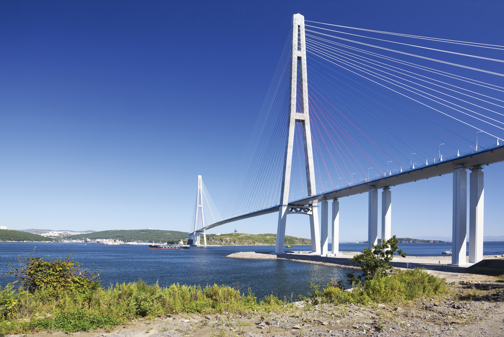
The main body of the Jiashao Bridge in China is measured at 2,680 meters, which makes it the most significant span using this design option when multiple connections are in place to create the final crossing. When looking at a single span option for a bridge, the longest in the world today is the Russky Bridge in Vladivostok Russia, which offers total coverage of 1,104 meters.
Although a cable-stayed bridge can help to provide a consistently supportive deck when there are crosswinds present over a span, this option does not work well when the speed of that wind remains consistently high. This disadvantage occurs because of the rigidity that the cables provide for the overall structure. In regular situations, this would contribute to a higher level of durability. Under the pressure of a high-speed crosswind, the deck would start rocking. Over time, this issue begins to loosen the support cables, making it possible for the structure to eventually fail over time.
We saw this disadvantage occur when a cable-stayed bridge collapsed in Genoa, Italy, on August 14, 2018. This bridge was built in 1967 and made largely of concrete, which is typical for the design. When it collapsed, the failure claimed 43 lives as motorists found themselves plunging into the depths below.
The design of most cable-stayed bridges will place the bundle areas for the support structures in regions where a physical inspection becomes very challenging. When you add in the reduction of anchors for the support structure, the routine maintenance for this design option can be intensive. Although communities might be able to save upwards of 30% on the installation costs for this option, the increase in labor costs for ongoing maintenance will eventually eat into those savings.
When you start talking about a bridge that must last 50-100 years, then a comm


 8613371530291