
wire rope bridge design pricelist

I’ve had several inquiries lately about the cost of building my bridge. I left prices out of my book because it depends on the current market and what is available in your local supply market. But here is what it would cost today to build this bridge near Eugene, Oregon.
*** Cable Locking System: *** Depends on where you have them made. Here they are about $12.50 each: 18 CLS pcs. per 1/2 bridge length @ $12.50 ea. $225.00
Be sure to check out my new book, Building a Small Cable Suspension Bridge. There is a link to purchase it here: http://www.wildcatman.com. There is also a link there to contact me.
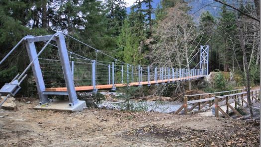
Bridges are the best way to connect two tree house platforms to each other. We also build bridges from the ground up to a tree house or from a back deck out to a tree house. Construction of a short rope bridge is a reasonably simple task. However, some suspension bridges span great distances and require more serious design & construction practices.
If you would like to build your own cable bridge like the ones we build, then check out the treehouse bridge kits at Treehouse Supplies. They do require assembly, but instructions and support are included.
The costs for small bridges in between tree house platforms normally range from $3000 to $20,000. The costs for large cable bridges can be between $60,000 and $500,000. The big price ranges are because the length and site specific factors can make the cost vary greatly. Remember that large bridges such as canyon crossings will require site visits, careful measurements, engineering, and large towers and/or footings to ensure safety.
Bridges can be made from different combinations of materials such as rope, cable, chain, steel, and wood. The choice is made based on the required strength, the intended use of the bridge, and the aesthetic preference of the owner or designer. Our preferred method is to use cable for the main suspension, and then netting on the sides to prevent little bridge visitors from falling off as they traverse. On shorter bridges, we can consider alternate methods such as a rope only bridge. Larger, more serious cable suspension bridges may require concrete footings, towers, and stiffer walking surfaces than wood planks.
Trees are very strong, but they are not accustomed to resisting large lateral forces. They can support a great deal of weight, especially near to the ground. The trouble is, with larger suspension bridges, the long upper cables are attached high in the tree and pull not straight down but inward to the center of the bridge. This is quite unnatural and with medium to large bridges, the limits of the trees can be exceeded even when guy wires are attached appropriately. In such cases, towers are erected to support each side of the bridge. These towers must be designed by qualified engineers in order to make sure that appropriate materials are custom fabricated for each bridge project.
To get started, we normally need to see the site, take measurements, and tell you what we can and can’t do for you, and what it will cost. We do charge for such site feasibility studies, and the fees are based on our travel costs and time spent on the visit. If you would like to get a free estimate before paying for the feasibility study, then please get us some preliminary information such as the rough topography, pictures, the length, and any other site specific factors that will help us give you an estimate in the form of an expected price range. Our estimates for rope, cable, or suspension bridges that are of reasonable length between two appropriate sized trees are generally pretty accurate, but for larger bridges, we normally can’t commit to the final price until we see it.
We built this bridge and wrote a “how we did it” book about the process a few years ago. I thought it would be fun to share the basics of this design as an Instructable for people who have enough skill to be able to take the information and work with it. And as we do in our book, we recommend having your specific design approved by an engineer just to be on the safe side.
Here is our design for an 80’ long walking bridge that spans our creek and is set back far enough for a serious flood. The challenge was to do as much as possible without the need of machinery or swimming. Even if your creek isn’t that wide, consider flood stage and go from there.
Dead men are a vital part of this design (the foundation in the ground). Engineered based on the load, they were were buried and secured before the suspension cables were brought in.
The stringers were also spaced to deal with harmonic resonance. Though keep in mind, it’s a suspension bridge and it will move when you walk on it. Whee!
This bridge has been our access across the creek to get to our spring for many years, and is holding up great through several major floods. A couple of trees have hit it, but it wasn’t phased. We recently adjusted the turnbuckles on the dead men cables to pull up the slack in the deck from tree hits.
Note that all photos and illustrations are from our book, Building a Small Cable Suspension Bridge with the Cable Locking System. The book is easily found on Amazon.com if you look it up, and our blog with more info is wildcatman.wordpress.com. Hopefully this is enough information to get you inspired!
Almost ten years ago we posted a materials list with prices for our 80" bridge. You can find that here, although obviously the prices will be outdated: https://wildcatman.wordpress.com/2013/04/18/cost-t...
We suspect a public park would want a bridge that was much more solid than this style, but "millions $" sounds pretty steep! Check out the designs here: https://www.aia.org/showcases/6121109-forest-park-...
The main cables are 1/2” and the suspenders are 3/16” galvanized cable. A complete materials list is here: https://wildcatman.wordpress.com/2013/04/18/cost-to-build-a-small-cable-suspension-bridge/0
im trying to make a suspension mini bridge for school to have a competition to see which bridge can holod the most weight how do i make a stable good suspension bridge?
Thanks for asking, and sorry, no. I could design a bridge like this for us but not for someone else, since I am not a licensed engineer. Good luck! Maybe check with Bridges to Prosperity and see if they"ll share a design with you?0
The main cables are 1/2” and the suspenders are 3/16” galvanized cable. A complete materials list is here: https://wildcatman.wordpress.com/2013/04/18/cost-to-build-a-small-cable-suspension-bridge/0
I"ve read the book and loved it. Thank you for putting this info together. It"s really motivating for people who"d like to start a similar undertaking. My question: is the suspended bridge style suitable for bridges with a grade, with two ends at different altitudes? If so, what kind of adjustments should be made to the project to account for the grade?
Thanks for the compliments on our book, and for your question. I don’t know what kind of altitude changes you’re talking about, but if they are minor, then it shouldn’t make any real difference. You can adjust where the bridge deck levels to the posts and then build a ramp or stairs to get up to it from the low side.
If you’re talking about a slope on the bridge deck (because cutting the high grade or ramping up to the low side isn’t an option) then the functionality of the bridge using the parts I employed won’t really be compromised because it’s a small bridge not meant for heavy loads. That said, I would however be concerned about safety on a bridge that isn’t level - not only the precarious feeling it could illicit in the person walking on it, it could be slippery.ReplyUpvote
Structural wire rope cables have played a major role in the engineering and architecture of many large structures and are widely used on projects involving bridges, vessels, stadiums and glass facade/membrane buildings to name a few. Using steel cables in the design of such projects has proved more cost effective than solely using raw materials such as Iron or concrete and is now very much the preferred choice within the construction and engineering sector.
The starting point for FATZER products is high-tensile steel wire. Fabricated into steel wire ropes, it enables architects, engineers and contractors to create technically sophisticated rope architecture.
FATZER manufacture a wide range of rope diameters, suitable for use on the most complex of projects. The performance parameters of all products are monitored and confirmed by independent test bodies.
It goes without saying that steel wire ropes must meet the highest safety requirements. What sets them apart though, is the way they provide freedom for aesthetically creative design. It is the elegant HYEND series of end connections, in particular, which turns these technical products into true “design objects”.
Spiral strand and fully locked coil ropes are manufactured in Switzerland in FATZER"s own factory. This covers the whole process including stranding, pre-stretching, marking and in some cases socketing. Handling customised product solutions is a challenge we tackle on a daily basis. In all cases rope assemblies arrive on site ready for installation.
All materials are fully certified and has full traceability in line with our ISO9001 procedures. The most common constructions of wire rope used for structural purposes are: Spiral strand ropes and fully locked coil rope (EN 1993-1-11:2006). All ropes are available with HYEND fittings to guarantee the best quality and safety standard (EN 13411-4).
SWR have the capacity to design and manufacture these assemblies, and can provide structural advice on load ratings and fixing terminals should this be required. Both galvanised and stainless steel can be used depending on the location and specification of the project.
Cable-stayed bridges are a subcategory of suspended structures. A cable-stayed bridge is similar to a suspension bridge in having towers and a deck-girder supported by cables; however, its diagonal cables transfer the vertical loads from the deck directly to the towers. Thus, the main deck-girder of a cable-stayed bridge works like a continuous beam on cable supports (more flexible than pier supports) with additional compression force throughout the deck. A cable-stayed bridge is also a prestressed system as its cable-stays are additionally tensioned to counterbalance a significant part of the vertical loads on the main deck-girder.
The Strömsund Bridge in Sweden, completed in 1956 with a 182-meter (597-foot) main span, is considered the first modern cable-stayed bridge. For the following 65 years, cable-stayed bridges have seen a dramatic increase in both the number of new structures and in long-span achievements. By 1995, there were only 3 cable-stayed bridges with spans over 500 meters (1,640 feet); 25 years later, there are already 67 cable-stayed bridges with spans over 500 meters (including three over 1,000 meters or 3,280 feet). Another 29 with spans over 500 meters, with some over 800 meters (2,624 feet), are currently under construction.
The efficient range of cable-stayed bridges is moving towards even longer spans. There is no other bridge structural system exhibiting such rapid development. Most cable-stayed bridges are visually beautiful, and some are among the most impressive of engineering achievements.
The idea for the cable-stayed system was perhaps inspired by the drawbridges of medieval castles and the rope-braced masts of tall ships. The very first documented image of a cable-stayed bridge appears in the Machinae Novae, a book by Fausto Veranzio published in 1615.
Predecessors for modern cable-stayed bridges appeared in the 19th century in the form of different hybrid combinations of suspension systems with additional diagonal straight cables, as in the case of the Albert Bridge, UK (1873). The best known of these hybrid structures is the Brooklyn Bridge, New York, 1883, with a 486-meter main span (1,594 feet), for which John Roebling used diagonal cables for stiffening the structure.
In the 1960s and 1970s, the system was developed further to replace many of the bridges destroyed in Germany during World War II. In this period, the system was also used for roof structures requiring long, column-free spaces in buildings. Initially, cable-stayed structures were used for bridge spans of 60 to 250 meters (196 to 820 feet) but today they span much longer distances and are the only system that challenges suspension bridges in super-long spans. Their spans grew to 302 meters (990 feet) in 1959 with the Severin Bridge (Germany), to 404 meters (1,325 feet) in 1974 with the Saint Nazaire Bridge (France), and 856 meters (2,808 feet) in 1995 with Michel Virlogeux’s Normandy Bridge (France). Today, the Russky Island Bridge (Russia) has the longest span of this system, 1,104 meters (3,622 feet) achieved in 2012 (Figure 1).
In the United States, we can mention the second Sunshine Skyway Bridge with a span 366-meter (1,200 feet) in 1987 (Florida), the Dames Point Bridge with a 396-meter span (1,300-foot) in Florida, and the Arthur Ravenel Bridge with a 471-meter span (1,545-foot) in 2005 (South Carolina).
The main elements of a cable-stayed bridge are towers or pylons, deck girder(s), cable-stays, anchorages, and foundations. Tower and pylon are interchangeable terms; lighter, slender towers are often called pylons. The classic cable-stayed bridges are symmetric with one central span, two side spans, and two towers; such are most cable-stayed bridges with spans above 600 meters. The back-up cables may extend over several side spans.
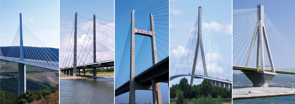
Asymmetric cable-stayed bridges have one main span and one side span, with a single tower. Multiple-span cable-stayed bridges have two or more (usually equal) main spans. Several examples are shown in Figure 2.
Some sub-divisions are used for cable-stayed bridges: extradosed, under-spanned (under-deck), cradle, inverted Fink truss, and tensegrity. The cables at the towers can be arranged in parallel (harp), fan, star, or mixed configuration. Various structural solutions are used for the towers: single pylons, double-leg portals (vertical, slightly angled, free-standing, or interconnected as a portal frame, with “A,” “H,” “Y,” or inverted “Y” shaped arches).
For deck-girders: beams of prestressed concrete or steel, box girders of prestressed concrete or steel, similar to those in modern suspension bridges;
For cables: high-strength steel wires, usually 270 grade (270 ksi, or 1,860 MPa), built from 7-wire, ⅜-inch (9.5 millimeters) strands per ASTM A886, other higher-grade steel wires, carbon fiber-reinforced polymers (CFRP), or composites. Prestressed concrete has been used in the past, but should be avoided as it has been proven unsafe on some failures such as the Morandi Bridge;
For long-span bridges, foundations on soft soils, or for bridges in high seismic areas, it is preferable to use predominantly steel structures to reduce the self-weight and the related earthquake forces.
The most important part of bridge design is the overall concept for the structure and its elements: the selection of the appropriate structural system for the bridge considering its specific function, site location, and required spans. A well-selected concept determines the efficiency and economy of the bridge, saves materials, cost, and construction time. Good design concepts minimize problems and future difficulties both in the design office and on the construction site.
For the design of early cable-stayed bridges, engineers used a relatively small number of cables. After acquiring more experience and with the introduction of structural design software, engineers were able to use a larger number of cable stays, reducing the demand on the deck girder and leading to greater efficiency and longer spans.
The basics of cable-stayed bridge design are as follows: the vertical loads on the deck are supported by diagonal cable stays that transfer these loads to the towers. At the tower, the horizontal components of the cables from the main span are in balance with those from the side/adjacent spans. The towers support and transfer the vertical load to the foundations. Similarly, the cumulative compression horizontal components of the loads from the main span are in balance with the compression load components of the side spans. Therefore, the entire bridge system is in balance with predominant compression forces in the towers and the deck system, and with tension forces in the cable stays. The system is self-balanced, provided that all elements are designed correctly to sustain the maximum demand from the highest possible combination of loads.
The challenge for the design engineer is to select an appropriate combination of the multiple possible variations of towers, cable-stay arrangements, and deck systems. Like all suspended structures, cable-stayed bridges are sensitive to deformations and it is necessary to check the deformed condition of the system for all load combinations, including those during the different phases of construction.
Today’s structural design software greatly assists engineers in the calculation of cable-stayed bridges. After choosing the main parameters of the system, it is essential to establish the start-up dimensions and sections of the deck-girder, cables, and towers. A simple design approach will help in setting up these dimensions.
For a start, the designer can use a substitution simply-supported beam for determining the approximate bending moments for the main span deck-girder. The upward cable-stays pretension can offset most of the moments from permanent loads on the deck. This is achieved with additional tensioning of the cables after erecting the main elements to counteract permanent loads, resulting in minimal vertical bending in the deck-girder. The cables should be additionally tensioned to counteract 50% of the combined temporary downward loads (live loads, wind, snow, ice, and earthquake). This way, the working bending moments of the deck-girder will vary during operation approximately between 50% of the positive moments (from the worst temporary load combination) to 50% of the negative moments from temporary loads. This “first step” determines the design moments for the main span deck-girder. The compression in the deck-girder due to the horizontal components of cable stays forces is the cumulative sum of these components, approximately 55 to 65% of the total vertical loads on the main span depending on the span, the number of cables, and the height of cable connections at the tower. The cumulative compression force (ΣPc) in the deck-girder is equal to the sum of all compression forces Pci at cable connections (Figure 4) at the deck: the tension cable force Pcable = Pv/sin α,
These calculations will allow the designer to establish the initial design dimensions for the cables, deck-girder, and tower to be used in the computer model for further adjustments and refinements of the system. The deck-girder has to be designed for the compression and bending from the cable-stay system and the typical bridge deck design for vertical dead and live loads. The initial approach described above will help to achieve the desired final goal faster.
Cable-stayed bridges are efficient in cost, materials, and construction time. They have better efficiency than other bridge systems, with the only competitor being suspension systems, while allowing for more straightforward construction methods. An additional advantage of cable-stayed bridges is their larger efficient span range from 100-meter spans (328 feet) to over 1,000-meter spans (3,280 feet).
The multitude of possibilities of the system provide engineers and architects with many design options. The “mid-long range” structures allow more creativity, originality, and possibilities for innovative work. A cable-stayed bridge does not need to be extravagant. The most straightforward bridge with a “sincere” structure is often the best and is usually elegant and attractive.
Cable-stayed bridges have a combination of elegance, slenderness, and a feeling of robustness. The national infrastructure’s demand for more bridges requires the priority of efficiency and economy.
Like all other bridge systems, cable-stayed bridges are continuously improved based on the development of high-strength materials and new construction technologies. More valuable for engineers are the modifications of established structural systems and newer sub-systems. In addition to the increased number of cable-stayed bridges with longer spans (above 600 meters or approximately 2,000 feet), there is increasing use of the system for pedestrian bridges. The lower loads and shorter spans allow engineers to explore new approaches, transforming the building of these bridges into a testing lab for innovation. As such, we may consider the extradosed, under-spanned, and inverted Fink truss sub-bridge systems, all oriented to improved efficiency.
One area of further development is the pursuit of combinations/hybrids of cable-stayed and suspension bridge systems for achieving super-long spans. The idea is to reduce the suspension span length by moving the suspension support points inward along the span. This not only reduces the suspension span length but the required tower height as well while allowing a longer clear span. This is obtained with “cable-stay cantilevered alternatives” at the bridge towers, adding “on-deck” cable-stayed pylons (Figure 5). With 500-meter (1,640-foot) cantilevers and cable-stayed “on-deck” pylons used on each side of a total clear span of 3,000 meters (9,842 feet), the suspension part is reduced to 2,000 meters (6,561 feet). Such reduction would allow using main suspension cables of the size and type of those already used in bridges, like the Akashi-Kaikyo at 1991 meters (6,532 feet), for a much longer main span.
Based on current technical progress and fast development, cable-stayed bridges may reach spans 2,400 to 2,600 meters (7,600 to 8,500 feet) in a short while; such design will require towers about 500 to 570 meters tall (1640 feet to 1,870 feet), something achievable, considering already completed skyscraper structures. This will extend the efficiency range for cable-stayed bridges to very long spans above 2,000 meters (6,561 feet). A hybrid cable-stayed-and-suspension system would make possible even longer spans of up to 3,000 to 3,400 meters (9,842 to over 11,000 feet), incorporating a “pure” suspension bridge of “only” 2,200 to 2,400 meters (7,218 to 7,874 feet).
Based on the efficiency and advantages of cable-stayed structures, American engineers and transportation agencies should consider more cable-stayed bridges when planning new projects. Greater use of cable-stayed bridges may upgrade the infrastructure with these efficient, faster built, and elegant structures. Making cable-stayed bridges more popular may also help our bridge engineering profession regain its position of leadership in the design and construction of long-span bridges.■
The double-decked George Washington Bridge, connecting New York City to Bergen County, New Jersey, is the world"s busiest suspension bridge, carrying 102 million vehicles annually.
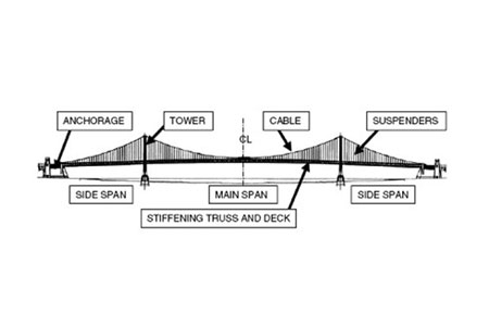
A suspension bridge is a type of bridge in which the deck is hung below suspension cables on vertical suspenders. The first modern examples of this type of bridge were built in the early 1800s.Simple suspension bridges, which lack vertical suspenders, have a long history in many mountainous parts of the world.
Besides the bridge type most commonly called suspension bridges, covered in this article, there are other types of suspension bridges. The type covered here has cables suspended between towers, with vertical suspender cables that transfer the live and dead loads of the deck below, upon which traffic crosses. This arrangement allows the deck to be level or to arc upward for additional clearance. Like other suspension bridge types, this type often is constructed without the use of falsework.
The suspension cables must be anchored at each end of the bridge, since any load applied to the bridge is transformed into a tension in these main cables. The main cables continue beyond the pillars to deck-level supports, and further continue to connections with anchors in the ground. The roadway is supported by vertical suspender cables or rods, called hangers. In some circumstances, the towers may sit on a bluff or canyon edge where the road may proceed directly to the main span, otherwise the bridge will usually have two smaller spans, running between either pair of pillars and the highway, which may be supported by suspender cables or their own trusswork. In the latter case, there will be very little arc in the outboard main cables.
The Manhattan Bridge, connecting Manhattan and Brooklyn in New York City, opened in 1909 and is considered to be the forerunner of modern suspension bridges; its design served as the model for many of the long-span suspension bridges around the world.
The earliest suspension bridges were ropes slung across a chasm, with a deck possibly at the same level or hung below the ropes such that the rope had a catenary shape.
The Tibetan siddha and bridge-builder Thangtong Gyalpo originated the use of iron chains in his version of simple suspension bridges. In 1433, Gyalpo built eight bridges in eastern Bhutan. The last surviving chain-linked bridge of Gyalpo"s was the Thangtong Gyalpo Bridge in Duksum en route to Trashi Yangtse, which was finally washed away in 2004.suspended-deck bridge, which is the standard on all modern suspension bridges today. Instead, both the railing and the walking layer of Gyalpo"s bridges used wires. The stress points that carried the screed were reinforced by the iron chains. Before the use of iron chains it is thought that Gyalpo used ropes from twisted willows or yak skins.
The first iron chain suspension bridge in the Western world was the Jacob"s Creek Bridge (1801) in Westmoreland County, Pennsylvania, designed by inventor James Finley.The Port Folio, in 1810.
Early British chain bridges included the Dryburgh Abbey Bridge (1817) and 137 m Union Bridge (1820), with spans rapidly increasing to 176 m with the Menai Bridge (1826), "the first important modern suspension bridge".Chain Bridge in Nuremberg. The Sagar Iron Suspension Bridge with a 200 feet span (also termed Beose Bridge) was constructed near Sagar, India during 1828-1830 by Duncan Presgrave, Mint and Assay Master.Clifton Suspension Bridge (designed in 1831, completed in 1864 with a 214 m central span), is similar to the Sagar bridge. It is one of the longest of the parabolic arc chain type. The current Marlow suspension bridge was designed by William Tierney Clark and was built between 1829 and 1832, replacing a wooden bridge further downstream which collapsed in 1828. It is the only suspension bridge across the non-tidal Thames. The Széchenyi Chain Bridge, (designed in 1840, opened in 1849), spanning the River Danube in Budapest, was also designed by William Clark and it is a larger-scale version of Marlow Bridge.
An interesting variation is Thornewill and Warham"s Ferry Bridge in Burton-on-Trent, Staffordshire (1889), where the chains are not attached to abutments as is usual, but instead are attached to the main girders, which are thus in compression. Here, the chains are made from flat wrought iron plates, eight inches (203 mm) wide by an inch and a half (38 mm) thick, rivetted together.
The first wire-cable suspension bridge was the Spider Bridge at Falls of Schuylkill (1816), a modest and temporary footbridge built following the collapse of James Finley"s nearby Chain Bridge at Falls of Schuylkill (1808). The footbridge"s span was 124 m, although its deck was only 0.45 m wide.
Development of wire-cable suspension bridges dates to the temporary simple suspension bridge at Annonay built by Marc Seguin and his brothers in 1822. It spanned only 18 m.Guillaume Henri Dufour"s Saint Antoine Bridge in Geneva of 1823, with two 40 m spans.Joseph Chaley"s Grand Pont Suspendu in Fribourg, in 1834.
In the United States, the first major wire-cable suspension bridge was the Wire Bridge at Fairmount in Philadelphia, Pennsylvania. Designed by Charles Ellet Jr. and completed in 1842, it had a span of 109 m. Ellet"s Niagara Falls suspension bridge (1847–48) was abandoned before completion. It was used as scaffolding for John A. Roebling"s double decker railroad and carriage bridge (1855).
Drawing of the Tibetan-built Chaksam bridge south of Lhasa, constructed in 1430, with long chains suspended between towers, and vertical suspender ropes carrying the weight of a planked footway below.
"View of the Chain Bridge invented by James Finley Esq." (1810) by William Strickland. Finley"s Chain Bridge at Falls of Schuylkill (1808) had two spans, 100 feet, and 200 feet.
Comparison of a catenary (black dotted curve) and a parabola (red solid curve) with the same span and sag. The main forces in a suspension bridge of any type are tension in the cables and compression in the pillars. Since almost all the force on the pillars is vertically downwards, and the bridge is also stabilized by the main cables, the pillars can be made quite slender, as on the Severn Bridge, on the Wales-England border. In a suspended deck bridge, cables suspended via towers hold up the road deck. The weight is transferred by the cables to the towers, which in turn transfer the weight to the ground.
The catenary represents the profile of a simple suspension bridge or the cable of a suspended-deck suspension bridge on which its deck and hangers have negligible mass compared to its cable. The parabola represents the profile of the cable of a suspended-deck suspension bridge on which its cable and hangers have negligible mass compared to its deck. The profile of the cable of a real suspension bridge with the same span and sag lies between the two curves.
The main cables of a suspension bridge will form a catenary; the cables will instead form a parabola if they are assumed to have zero weight. One can see the shape from the constant increase of the gradient of the cable with linear (deck) distance, this increase in gradient at each connection with the deck providing a net upward support force. Combined with the relatively simple constraints placed upon the actual deck, that makes the suspension bridge much simpler to design and analyze than a cable-stayed bridge in which the deck is in compression.
In suspension bridges, large main cables (normally two) hang between the towers and are anchored at each end to the ground. The main cables, which are free to move on bearings in the towers, bear the load of the bridge deck. Before the deck is installed, the cables are under tension from their own weight. Along the main cables smaller cables or rods connect to the bridge deck, which is lifted in sections. As this is done, the tension in the cables increases, as it does with the live load of traffic crossing the bridge. The tension on the main cables is transferred to the ground at the anchorages and by downwards compression on the towers.
In cable-stayed bridges, the towers are the primary load-bearing structures that transmit the bridge loads to the ground. A cantilever approach is often used to support the bridge deck near the towers, but lengths further from them are supported by cables running directly to the towers. By design, all static horizontal forces of the cable-stayed bridge are balanced so that the supporting towers do not tend to tilt or slide and so must only resist horizontal forces from the live loads.
Except for installation of the initial temporary cables, little or no access from below is required during construction and so a waterway can remain open while the bridge is built above.
Bridge decks can have deck sections replaced in order to widen traffic lanes for larger vehicles or add additional width for separated cycling/pedestrian paths.
The relatively low deck stiffness compared to other (non-suspension) types of bridges makes it more difficult to carry heavy rail traffic in which high concentrated live loads occur.
Some access below may be required during construction to lift the initial cables or to lift deck units. That access can often be avoided in cable-stayed bridge construction.
In an underspanned suspension bridge, also called under-deck cable-stayed bridge,Guillaume Henri Dufour;Robert Stevenson for a bridge over the River Almond near Edinburgh.
The main suspension cables in older bridges were often made from a chain or linked bars, but modern bridge cables are made from multiple strands of wire. This not only adds strength but improves reliability (often called redundancy in engineering terms) because the failure of a few flawed strands in the hundreds used pose very little threat of failure, whereas a single bad link or eyebar can cause failure of an entire bridge. (The failure of a single eyebar was found to be the cause of the collapse of the Silver Bridge over the Ohio River.) Another reason is that as spans increased, engineers were unable to lift larger chains into position, whereas wire strand cables can be formulated one by one in mid-air from a temporary walkway.
Poured sockets are used to make a high strength, permanent cable termination. They are created by inserting the suspender wire rope (at the bridge deck supports) into the narrow end of a conical cavity which is oriented in-line with the intended direction of strain. The individual wires are splayed out inside the cone or "capel", and the cone is then filled with molten lead-antimony-tin (Pb80Sb15Sn5) solder.
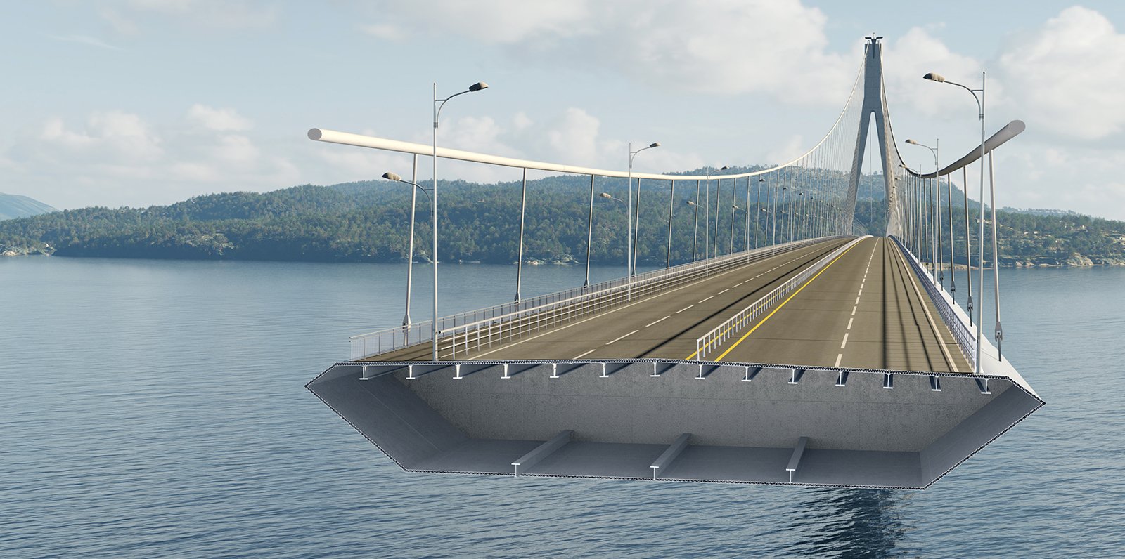
Most suspension bridges have open truss structures to support the roadbed, particularly owing to the unfavorable effects of using plate girders, discovered from the Tacoma Narrows Bridge (1940) bridge collapse. In the 1960s, developments in bridge aerodynamics allowed the re-introduction of plate structures as shallow box girders, first seen on the Severn bridge, built 1961–1966. In the picture of the Yichang Bridge, note the very sharp entry edge and sloping undergirders in the suspension bridge shown. This enables this type of construction to be used without the danger of vortex shedding and consequent aeroelastic effects, such as those that destroyed the original Tacoma Narrows bridge.
Three kinds of forces operate on any bridge: the dead load, the live load, and the dynamic load. Dead load refers to the weight of the bridge itself. Like any other structure, a bridge has a tendency to collapse simply because of the gravitational forces acting on the materials of which the bridge is made. Live load refers to traffic that moves across the bridge as well as normal environmental factors such as changes in temperature, precipitation, and winds. Dynamic load refers to environmental factors that go beyond normal weather conditions, factors such as sudden gusts of wind and earthquakes. All three factors must be taken into consideration when building a bridge.
The principles of suspension used on a large scale also appear in contexts less dramatic than road or rail bridges. Light cable suspension may prove less expensive and seem more elegant for a cycle or footbridge than strong girder supports. An example of this is the Nescio Bridge in the Netherlands, and the Roebling designed 1904 Riegelsville suspension pedestrian bridge across the Delaware River in Pennsylvania.Arouca Geopark, Portugal, opened in April 2021. The 516 metres bridge hangs 175 meters above the river.
Where such a bridge spans a gap between two buildings, there is no need to construct special towers, as the buildings can anchor the cables. Cable suspension may also be augmented by the inherent stiffness of a structure that has much in common with a tubular bridge.
Suspender cables and suspender cable band on the Golden Gate Bridge in San Francisco. Main cable diameter is 36 inches (910 mm), and suspender cable diameter is 3.5 inches (89 mm).
Typical suspension bridges are constructed using a sequence generally described as follows. Depending on length and size, construction may take anywhere between a year and a half (construction on the original Tacoma Narrows Bridge took only 19 months) up to as long as a decade (the Akashi-Kaikyō Bridge"s construction began in May 1986 and was opened in May 1998 – a total of twelve years).
Where the towers are founded on underwater piers, caissons are sunk and any soft bottom is excavated for a foundation. If the bedrock is too deep to be exposed by excavation or the sinking of a caisson, pilings are driven to the bedrock or into overlying hard soil, or a large concrete pad to distribute the weight over less resistant soil may be constructed, first preparing the surface with a bed of compacted gravel. (Such a pad footing can also accommodate the movements of an active fault, and this has been implemented on the foundations of the cable-stayed Rio-Antirio bridge.) The piers are then extended above water level, where they are capped with pedestal bases for the towers.
From the tower foundation, towers of single or multiple columns are erected using high-strength reinforced concrete, stonework, or steel. Concrete is used most frequently in modern suspension bridge construction due to the high cost of steel.
Temporary suspended walkways, called catwalks, are then erected using a set of guide wires hoisted into place via winches positioned atop the towers. These catwalks follow the curve set by bridge designers for the main cables, in a path mathematically described as a catenary arc. Typical catwalks are usually between eight and ten feet wide and are constructed using wire grate and wood slats.
High strength wire (typically 4 or 6 gauge galvanized steel wire), is pulled in a loop by pulleys on the traveler, with one end affixed at an anchorage. When the traveler reaches the opposite anchorage the loop is placed over an open anchor eyebar. Along the catwalk, workers also pull the cable wires to their desired tension. This continues until a bundle, called a "cable strand" is completed, and temporarily bundled using stainless steel wire. This process is repeated until the final cable strand is completed. Workers then remove the individual wraps on the cable strands (during the spinning process, the shape of the main cable closely resembles a hexagon), and then the entire cable is then compressed by a traveling hydraulic press into a closely packed cylinder and tightly wrapped with additional wire to form the final circular cross-section. The wire used in suspension bridge construction is a galvanized steel wire that has been coated with corrosion inhibitors.
At specific points along the main cable (each being the exact distance horizontally in relation to the next) devices called "cable bands" are installed to carry steel wire ropes called Suspender cables. Each suspender cable is engineered and cut to precise lengths, and are looped over the cable bands. In some bridges, where the towers are close to or on the shore, the suspender cables may be applied only to the central span. Early suspender cables were fitted with zinc jewels and a set of steel washers, which formed the support for the deck. Modern suspender cables carry a shackle-type fitting.
Special lifting hoists attached to the suspenders or from the main cables are used to lift prefabricated sections of the bridge deck to the proper level, provided that the local conditions allow the sections to be carried below the bridge by barge or other means. Otherwise, a traveling cantilever derrick may be used to extend the deck one section at a time starting from the towers and working outward. If the addition of the deck structure extends from the towers the finished portions of the deck will pitch upward rather sharply, as there is no downward force in the center of the span. Upon completion of the deck, the added load will pull the main cables into an arc mathematically described as a parabola, while the arc of the deck will be as the designer intended – usually a gentle upward arc for added clearance if over a shipping channel, or flat in other cases such as a span over a canyon. Arched suspension spans also give the structure more rigidity and strength.
Suspension bridges are typically ranked by the length of their main span. These are the ten bridges with the longest spans, followed by the length of the span and the year the bridge opened for traffic:
Union Bridge (England/Scotland, 1820), the longest span (137 m) from 1820 to 1826. The oldest suspension bridge in the world still carrying road traffic.
Bear Mountain Bridge (USA, 1924), the longest suspension span (497 m) from 1924 to 1926. The first suspension bridge to have a concrete deck. The construction methods pioneered in building it would make possible several much larger projects to follow.
Benjamin Franklin Bridge (USA, 1926), replaced Bear Mountain Bridge as the longest span at 1,750 feet between the towers. Includes an active subway line and never-used trolley stations on the span.
San Francisco–Oakland Bay Bridge (USA, 1936). This was once the longest steel high-level bridge in the world (704 m).cantilever bridge) has been replaced with a self-anchored suspension bridge which is the longest of its type in the world. It is also the world"s widest bridge.
Golden Gate Bridge (USA, 1937), the longest suspension bridge from 1937 to 1964. It was also the world"s tallest bridge from 1937 to 1993, and remains the tallest bridge in the United States.
Rod El Farag Bridge (Egypt, 2019), a modern Egyptian steel wire-cables based suspension bridge crossing the river Nile, which was completed in 2019 and holds the Guinness World Record for the widest suspension bridge in the world with a width of 67.3 meters, and with a span of 540 meters.
Broughton Suspension Bridge (England) – Iron chain bridge built in 1826. One of Europe"s first suspension bridges, it collapsed in 1831 due to mechanical resonance induced by troops marching in step. As a result of the incident, the British Army issued an order that troops should "break step" when crossing a bridge.
Silver Bridge (USA) – Eyebar chain highway bridge, built in 1928, that collapsed in late 1967, killing forty-six people. The bridge had a low-redundancy design that was difficult to inspect. The collapse inspired legislation to ensure that older bridges were regularly inspected and maintained. Following the collapse a bridge of similar design was immediately closed and eventually demolished. A second similarly-designed bridge had been built with a higher margin of safety and remained in service until 1991.
Tacoma Narrows Bridge, (USA), 853 m – 1940. The Tacoma Narrows bridge was vulnerable to structural vibration in sustained and moderately strong winds due to its plate-girder deck structure. Wind caused a phenomenon called aeroelastic fluttering that led to its collapse only months after completion. The collapse was captured on film. There were no human deaths in the collapse; several drivers escaped their cars on foot and reached the anchorages before the span dropped.
Peace River Suspension Bridge (Canada) The north anchor"s soil support for the suspension bridge, which was completed in 1943, failed over a few days in October 1957, and the entire bridge subsequently collapsed.
On 30 October 2022, Jhulto Pul, a pedestrian suspension bridge over the Machchhu River in the city of Morbi, Gujarat, India collapsed, leading to the deaths of at least 141 people.
Cable-stayed bridge — superficially similar to a suspension bridge, but cables from the towers directly support the roadway, rather than the road being suspended indirectly by additional cables from the main cables connecting two towers.
Inca rope bridge — has features in common with a suspension bridge and predates them by at least three hundred years. However, in a rope bridge the deck itself is suspended from the anchored piers and the guardrails are non-structural.
Simple suspension bridge — a modern implementation of the rope bridge using steel cables, although either the upper guardrail or lower footboard cables may be the main structural cables.
"Port Authority of New York and New Jersey - George Washington Bridge". The Port Authority of New York and New Jersey. Archived from the original on 20 September 2013. Retrieved 13 September 2013.
Bod Woodruff; Lana Zak & Stephanie Wash (20 November 2012). "GW Bridge Painters: Dangerous Job on Top of the World"s Busiest Bridge". ABC News. Archived from the original on 28 September 2013. Retrieved 13 September 2013.
"Marlow Suspension Bridge". Retrieved 11 December 2008. Cove-Smith, Chris (2006). The River Thames Book. Imray Laurie Norie and Wilson. ISBN 0-85288-892-9.
Drewry, Charles Stewart (1832). A Memoir of Suspension Bridges: Comprising The History of Their Origin And Progress. London: Longman, Rees, Orme, Brown, Green & Longman. Archived from the original on 16 June 2013. Retrieved 13 June 2009.
McGloin, Bernard. "Symphonies in Steel: Bay Bridge and the Golden Gate". Virtual Museum of the City of San Francisco. Archived from the original on 25 February 2011. Retrieved 12 January 2008.
New York State"s longest bridge is in dire straits. “At times, you can see the river through the cracks in the pavement,” President Barack Obama said at a press conference in front of the Tappan Zee Bridge in May 2014. “Now, I"m not an engineer, but I figure that"s not good.”
It"s not. The three-mile-long Tappan Zee carries 138,000 vehicles a day over the Hudson River. It is also “functionally obsolete” and as such exemplifies America"s crumbling infrastructure: about one in 10 bridges in the country merits the disturbing designation of “structurally deficient,” according to a 2013 report by the U.S. Department of Transportation. Built in 1955, the Tappan Zee has aged beyond its 50-year design life, like many of the steel crossways constructed during the nation"s most fervent bridge-building days in the 1950s and 1960s. And now the cantilever bridge—a structure that distributes weight over beams anchored to the shore—costs $50 million a year to maintain. It is in such bad shape that Obama fast-tracked a replacement: a cable-stayed bridge, which distributes weight with cables and towers.
The cable-stayed bridge debuted in its full form in the U.S. in the 1970s, decades after engineers in Europe honed the design. Today, because of improvements in structural modeling, this method is often a civil engineer"s first choice for bridges up to 3,000 feet long. They go up faster than alternative approaches and cost less because they use less material. The Tappan Zee"s replacement, currently called the New NY Bridge, will take shape this spring as crews begin to work above the water on the steel underpinnings of the road. Cable-stayed bridges are also under construction in Portland, Ore., Louisville, Ky., and Los Angeles. “They"re becoming a go-to type in the U.S.,” says Andrew Herrmann, a former president of the American Society of Civil Engineers.
The design"s closest relative is the suspension bridge—the difference between the two lying largely in how the cables are strung. In a suspension structure, such as the Golden Gate Bridge, there are two sets of cables: primary cables that connect the towers to one another and secondary cables that hang from the first set and hold the roadbed in place. A cable-stayed bridge, in contrast, has only cables that run directly from the towers to the road. Suspension bridges also require large anchors—typically huge blocks of concrete—at either end to hold them in place, whereas the weight of the road deck of a cable-stayed bridge is balanced evenly on each side of its towers and so does not need anchors.
When completed, the New NY Bridge will have eight traffic lanes and be the widest cable-stay in the world at a cost of approximately $3.9 billion. Its erection is long overdue. Bridges throughout the Northeast, which have tolerated 50 or more years of harsh winters, are in worse shape than most. “Even though this bridge will be the first cable-stay in New York State, it won"t be the last,” says David Capobianco, a project manager for the new bridge. “Cable-stays are definitely here to stay.” The construction company expects that the structure will last for 100 years and that the first vehicles will cross it in late 2016.
A cable-stayed bridge offers a design that is similar to a suspended bridge It will have towers that help to support the structure, while the deck is held in place by cables. The difference in the design is that the cables hold the deck by connecting it directly to the support pillars instead of using suspending wires or cables to stabilize the span.
This bridge type is useful for numerous traffic options, including automobiles, trucks, bicycles, and pedestrians. In some situations, a cable-stayed bridge is suitable for light rail as well. Engineers use this option when a span must be longer than what a cantilever bridge can support because of its weight, yet it is also short enough so that a suspension bridge is not the most practical option.
The first cable-stayed bridge in history is credited to Fausto Veranzio, who published his idea about this design in his work entitled Machinae Novae. The first bridges that were actually built using this method bean to appear in the 19th century. Many of the first suspension bridges would use elements of this design option as well. That includes several famous designs, including Brooklyn Bridge, Victoria Bridge, and Albert Bridge.
One of the most significant advantages to consider when evaluating a cable-stayed bridge is the amount of time required to complete the construction. This option does not require the same levels of anchoring that you will find in alternative designs. There are also fewer cables required to help support the deck because of how it ties to the support pillars or towers.
Because the cable-stayed design is similar to a suspension bridge, it is only natural to compare the two option. In most situations, the former will offer more strength to span a gap than the latter. The cable-stayed bridge can handle more pressure on a consistent basis compared to the suspension design, allowing the deck to have more resilience against wear and tear because there is greater rigidity in its construction.
There is also an element of resilience against natural pressures which may impact the bridge in negative ways over time. It withstands the shaking mechanisms of an earthquake better than most other bridge types. You can potentially place it in locations where a cross-wind might make other designs unsuitable for the span. It will even maintain its shape better while supporting the heavy loads.
Because there are fewer labor elements to consider with this design, the installation costs can be significantly less because there are fewer manhours involved. Most designs are roughly 30% cheaper to construct when comparing the cost to other design options that are available today to cross that span. This advantage is one of the primary reasons why this type of bridge is the most common type that you will see when traveling on roadways around the world. The cost factor is so cheap that some communities have found that a new bridge using this design is less expensive than trying to maintain an older design indefinitely.
Although the span length of a cable-stayed bridge is restricted because of its design, what is unique about this option is that engineers can connect different spans together with the support pillars or towers to create a bridge of almost indefinite length. The Jiaxing-Shaoxing Sea Bridge is one such example of this advantage at work, offering consistent support for a span that is over 6.2 miles in length.
Sometimes called the Jiashao Bridge, this span allows drivers to cross Hangzhou Bay without difficulty as it can accommodate up to eight lanes of traffic at once. Drivers can travel at speeds above 60 miles per hour safely while using the structure. Local laws prevent vehicles with a max speed of 45mph from using the span. Construction was completed on July 6, 2013, with traffic using it about two weeks later.
Engineers have several different options that they can use when designing a cable-stayed bridge to cross a span. The side-spar design tends to be the most common as it offers only one tower, requiring supports that are on just one side of the structure. Some locations may require a cantilever-spar design, which provides a single spar that is found on one side of the bridge. You can also use cradle systems, multiple span options (like the Jiashao Bridge), or extra-dosed options to create the needed supports for a consistent deck that can support the expected weight that will be placed on the structure one day.
The cables that are used to create consistency and stability for this bridge design provide the structure with the temporary and permanent supports it requires simultaneously. Whenever more weight is added to one specific section of the bridge, then the cables will help to displace the extra pressure throughout the remainder of the structure to prevent one section from receiving the brunt of the stress. These cables will also maintain the stability of the structure as it distributes the unexpected pressure, allowing for safe usage in almost any situation.
Although a suspension bridge and a cable-stayed bridge look very similar in their final design, the one significant advantage that you will find with the latter option is that the symmetry one can build into the span can help it to provide more stability and strength. When the spans on either side of the pillar or tower are of the same length, then the horizontal forces help to balance out the effects of each other. That means there are fewer requirements for large ground anchors to ensure the structure can remain supportive as traffic passes along the deck.
When the decision is made to install a cable-stayed bridge to cover a span that is usually 3,000 feet or less in length, then there are four different types of rigging for the cables from which to choose. Each offers unique benefits that can lead to a better user experience for the local community.
• The mono design for a cable-stayed bridge uses a single cable from its towers to provide support. This option is rarely seen unless the span being crossed is relatively small.
• The parallel design, sometimes referred to as a harp option, offers cables that are virtually parallel to each other so that the height of their attachment is proportion to their distance from the tower and their deck mounting.
• The fan design requires that the cables all connect to or pass over the top of the towners. This option is preferred when access is necessary to the cables while maximum supports are needed to create a stable deck. Engineers can modify this option for specific environmental requirements too.
• The star design spaces the cables apart on the tower, connecting to one point or closely-spaced points on the deck instead of being spread out across the entire span.
One of the most common design options for a cable-stayed bridge is called the “single arrangement.” This option uses on column for cable support, usually through a projection in the center of the deck. It can also be placed along one of the sides of the structure. If a double arrangement is used, then pairs of columns are placed on both sides of the deck. The portal arrangement adds a third member that connects the tops of the two columns to create a visual effect that is reminiscent to a door-like shape, offering additional strength for traverse loads.
The final option is called the “A-shaped arrangement,” which achieves the same goal as the portal design by angling the two columns toward each other so that they meet at the time. Depending on the exact structure of the bridge, designers can have the columns be vertacle, curved, or angled relative to the bridge deck.
The introduction of computer-aided design for cable-stayed bridges has helped architects and engineers make the maximum range of a span longer now than ever before, but this option still has limits. Most of these bridges will cover a span that is between 100 to 1,100 meters in length. That is why they are an exceptionally attractive option for pedestrian bridges or places where unusual loading configurations might be present.
The main body of the Jiashao Bridge in China is measured at 2,680 meters, which makes it the most significant span using this design option when multiple connections are in place to create the final crossing. When looking at a single span option for a bridge, the longest in the world today is the Russky Bridge in Vladivostok Russia, which offers total coverage of 1,104 meters.
Although a cable-stayed bridge can help to provide a consistently supportive deck when there are crosswinds present over a span, this option does not work well when the speed of that wind remains consistently high. This disadvantage occurs because of the rigidity that the cables provide for the overall structure. In regular situations, this would contribute to a higher level of durability. Under the pressure of a high-speed crosswind, the deck would start rocking. Over time, this issue begins to loosen the support cables, making it possible for the structure to eventually fail over time.
We saw this disadvantage occur when a cable-stayed bridge collapsed in Genoa, Italy, on August 14, 2018. This bridge was built in 1967 and made largely of concrete, which is typical for the design. When it collapsed, the failure claimed 43 lives as motorists found themselves plunging into the depths below.
The design of most cable-stayed bridges will place the bundle areas for the support structures in regions where a physical inspection becomes very challenging. When you add in the reduction of anchors for the support structure, the routine maintenance for this design option can be intensive. Although communities might be able to save upwards of 30% on the installation costs for this option, the increase in labor costs for ongoing maintenance will eventually eat into those savings.
When you start talking about a bridge that must last 50-100 years, then a community will eventually pay more for this structure than they would with other designs despite the lower initial capital costs.
Most of the cable-stayed bridges that are built today use a combination of concrete and steel to create a rigid, supportive structure. Unless there are protections in place that maintain the quality of the metals used for the span, the support cables can be highly susceptible to corrosion and rust. Even if the materials do not show signs of this issue, the higher levels of fatigue that even a minor problem might create could have a devastating effect on the health of the bridge.
That is why you will see coastal regions painting their bridges with a water-resistant material to prevent the effects of corrosion due to the salt in the air. This issue is why you do not typically see cable-stayed bridges of a significant length anywhere in North America. The Baluarte Bridge in Mexico, at 520 meters in the longest on the continent. It is also the highest bridge, standing over 1,320 feet over the river below. In just 6 years of use, the total maintenance cost for the structure are over $132 million.
The cable-stayed bridge design fell out of favor in the early 20th century because it simply lacked the strength to support traffic. Although it was still used for short-to-medium spans, suspension bridges and other design options grew in use because they offered more durability despite the higher costs of installation. It was only when funds became scarce during the massive rebuilding efforts of the 1940s and 1950s that this option made a dramatic comeback. Even with computer-aided designs extending the reach of this design, it is still far behind the length of spans that other bridge options could provide for a community.
When the populations of the planet began to recover after the devastating effects of World War II, the cable-stayed bridge design began to take on a higher priority. This structure could be built quickly and cheaply to create the necessary infrastructure to support the rebuilding effort. Although the idea was far from new, it was an option that seemed to check all of the necessary boxes.
These bridges are aesthetically pleasing, incredibly strong, and exceptionally durable. Many of the first designs that were built in the late 19th century are still standing today, with most still used for their initial purpose. Computer-aided designs are now letting architects and engineers maximize the potential of this option.
The advantages and disadvantages of cable-stayed bridges must involve more than consistency and cost. We must consider the needs of the actual span, the amount of traffic the bridge must support, and what potential disasters could impact the structure one day. Although this option may not be suitable in every situation, the actual benefits it provides almost always outweigh the potential disadvantages, which is why it is such a popular bridge design.

If you are an engineering contractor or civil engineer intending to work on bridge projects, here is a refresher of the basic principles behind each type. A quick read-through may help to ensure you’re well informed when discussing bridge projects with your colleagues and customers.
In case you were wondering, there is no single answer to the question ‘What is the best type of bridge?’ This is because many factors need to be considered, such as location, the span required, weight and volume of traffic, resources, and the budget available.
Arch types of bridges use one or more arches as the main structural component, with the arches positioned beneath the deck. This method dates back many thousands of years, with stone and brick being the most commonly used materials. However, in modern times you will see arch bridges constructed from concrete.
Whatever material is used the principle remains the same: An arch bridge uses compression – downward pressure from the deck travels laterally towards the keystone and to the supporting structures at each end of the bridge (the abutments).
Beam bridges are the simplest type of bridge. In its most basic form, all that is needed is a crossbeam long enough to cover the span, and support from abutments under each end. To achieve a longer continuous span, (e.g., over 250 ft (80 m), piers need t


 8613371530291