
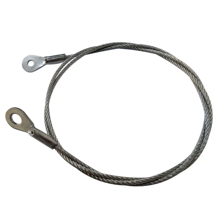
wire rope cable splicing free sample

The present invention is related to splicing or wire ropes or cables, particularly for those used for uphill and overhead transportation systems and the like wherein strength and smoothness and an assured rope life are essential to safe and reliable operation of such systems.
With increasing traffic and use of uphill and overhead transportation systems such as ski lifts, amusement park skyrides and tour sightseeing rides, the need for safe, reliable and minimum maintenance of the wire rope and cabling which transmit the power as well as actually effecting the transport of passengers has become all the more important. Moreover, provision of strong splices, long life and smooth rides are of extreme importance in such transportation systems. The wire rope cables frequently convey passengers over the most rugged of terrains and replacement of cables is accordingly difficult, dangerous and desirably kept to a minimum.
The wire rope splice which constantly passes over the support sheaves of such systems, thus should conform uniformly over its length to the diameter of the main body and should be without bulges or recesses in the wire rope surface. The rope system is otherwise likely subject to vibrations and jerks in passage between towers and over numerous sheaves and about drive and take-up wheels during operation with consequent unnecessary shock stressing of the rope and shortening of the life of the wire rope, particularly in the splice region.
In view of the foregoing, it is an object of the present invention to provide a wire rope splice assembly and components which will enable provision of a strong connection of ends in conformity with the diameter of the main body of the rope to impart a smoothness in operation and to promote a longer rope life.
Another object of the invention is to provide a stable splice arrangement for wire ropes and cables having minimum or no recesses, indentations or bulges in the exposed rope surface.
Still another object of the invention is to provide a strong wire rope splice assembly wherein positive inter-engagement of the outer and inner strands in the splice region is promoted under loading.
Another and still further object of the invention is to provide a splice for wire ropes wherein weakness or damage due to abrasion between strands and the core as well as strand portions located in the core region are reduced to increase the life of such ropes in use.
In the prior art, where the usual wire rope has six strands helically laid about a core, it is well known to form a splice over a long length of the rope by pairing up oppositely extending ends of equal lengths of the rope and tucking three strands of each into spaced apart core regions of the other. Portions of the core of each end are removed for lengths correspondingly generally to the length of the strand end portions to be tucked therein. The outer strand portions to be tucked into the core region of the splice are covered or wound with cotton, duct, twine or friction tape to protect the strands against inter-abrasion in the tuck regions. Such protective materials, although providing a degree of protection and increased life, are particularly vulnerable to wear, breakdown and deterioration, not only because of stresses of heavy loading and working as by flexing and twisting and abrasion in use, but also because of the extreme weather and other environmental conditions to which such ropes and cables are frequently subjected.
The splice in a wire rope or cable is usually the poorest portion since any distortion in the region causes a greater working of the material in the splice region than the remainder of the rope thereby promoting a progressive weakening of the splice. According to the present invention where long splices are made such as by tucking a length of each strand end individually into the core region of the wire rope, each such strand end is enclosed in a continuous tubular sheath to fill the space left by removal of the core and to protect the strands in the tuck region against wear.
The center of core region of a wire rope is usually a little larger than the diameter of the outer strand and voids are presented when an outer strand is inserted in the core region. Where the wire rope is the usual steel rope, a protective and filling sheath about the tucked portion of steel strand is desirably of bearing type material such as copper, aluminum, lead and alloys thereof or synthetic resin material such as nylon which will be compatible in wear resistance which although not fully understood is believed to be provided by a cushioning action which reduces scarfing and frictional abrasion between the center and outer steel strands. Also when such tubing is placed around the strand in the core region, lubrication materials in the strand are locked in which not only assures prolonged lubrication but reduces the possibilities of dry rust from forming.
The metal of the strand enclosing sheath is preferably made different in hardness from that of the wire rope. It is well known that dissimilar materials such as steel and bronze are more compatible in frictional relation, as in a bearing than one material against itself such as steel on steel in frictional engagement. This combination of a hard surface metal and a contacting softer bearing type material surface results in an excellent bearing interface combination and this property is embodied in the present invention to reduce the effects of abrasion in the splice region.
Another aspect of the invention is that where a void is formed such as at each point of crossover or intersection between two strands tucked into the core region of the wire rope, a filler member is provided to back up the strand portions in the region to contribute to conformity of the strands to the exterior dimension and shape of the rope at each of the splice intersections. The filler and back-up member it is found lessens distortion of the strands in the crossover regions and promotes longer life of the wire rope in the spliced region. Like the sheath member, the filler member may be of metal such as copper, aluminum, lead or alloys thereof or resinous material such as nylon which will act compatibly to reduce results from abrasion with steel strands of the rope.
FIG. 1 is a general overall view of a portion of an uphill wire rope or cable transportation system such as a ski lift in which the protective splice members and splice assembly of the present invention may be advantageously utilized;
FIG. 2 shows two ends of a wire rope to be spliced with a "V" designating each of the regions along the length of the main body of the rope at which a strand of one end is to be crossed with a corresponding strand of the other end tucked into the core region of the other end of the rope;
FIG. 4 is a schematic layout of the strand and core arrangement of the spliced rope of FIG. 3 illustrating the location of protective sheaths over each tucked strand end and intermediate core sections of the rope;
FIG. 5 is an enlarged view of a strand crossover region of the spliced cable with two strands of the rope deleted to illustrate more clearly the location of the protective strand sheaths of the invention;
FIG. 6 is a slightly longer view of the crossover region of FIG. 5 with deleted strands shown in dotted lines and showing the manner in which the sheathed strand portion is aligned with and extends to the core portion of the rope;
FIG. 7 is a view of a strand crossover region of a rope splice as illustrated in FIGS. 2-6 showing a protective filler and back-up member of the present invention located in and conforming in general shape to the space formed in the strand crossover region; and
Referring to the drawings in greater detail, FIG. 1 illustrates a ski lift representative of an uphill transportation system wherein a spliced cable or wire rope is passed over a series of sheaves for uphill conveyance of passengers. A rope support 11 extending laterally from a tower 10 incorporates a series of sheaves 12 over which a wire rope 25 passes. A series of chairs, represented by a double chair 14 are each supported from its respective bar 16 secured to and hanging from the wire rope 25. The longer the upward incline, the greater the number of sheaves the wire rope is required to pass over and correspondingly the greater the loading and working on the wire rope in conveying passengers uphill. Strength and uniformity of the splice in the wire rope accordingly is all the more important to long life and safety of the entire system.
The ski lift of FIG. 1 is representative of a number of uphill and overhead transportation systems utilizing wire ropes and cables in which the protective splice members and splice assembly of the present invention may be particularly advantageously utilized. Chairlifts, T-bar lifts, sky rides tramways and other transportation systems utilizing wire ropes or cables for power transmission and passenger conveyance are all of a type in which safety is of extreme importance as imparted by the structural features of the present invention.
FIG. 2 illustrates the manner in which a long splice can be made of two ends 26 and 27 of the wire rope 25 in which the protective components of the present invention lend themselves particularly to imparting safety and a longer life of such a splice assembly. The opposite ends 26 and 27 of the wire rope are first unwound and the fibrous core sections are removed therefrom. Commercial wire ropes usually have six strands distributed helically about a core of metal or of fiber. The point M at which the two ends 26 and 27 are unwound to free the strands for subsequent weaving into a splice is termed the marriage point. Three of the strands of each end are cut back to predetermined points beyond the marriage point leaving three free strand ends to be mated with corresponding strands at the spaced tuck positions a, b, c and d, e and f of wire rope 25. In tucking an end portion of a strand into the core region of the wire rope, a dagger tool is used to form an opening between strands. A tucker tool is placed in the opening between the strands and the fiber core is removed with a pair of pliers as the tucking progresses. The corresponding strands of the opposite ends of the rope are mated in each of these tuck positions by being crossed over and inserted in the core space of the other end of the rope.
FIG. 3 illustrates the spliced rope 25 and the tuck positions or regions a, b and c on one side of the marriage point M and positions d, e and f on the other in which crossovers of corresponding pairs of strands are effected and tucked into the core space of the rope.
FIG. 4 illustrates in plan view the arrangement of the corresponding strand ends in each of the tuck regions of FIG. 3 and illustrates how the strand layout pattern would appear if the helically oriented strands in the splice region were unwound and laid out flat on either side of the core strand 30 of the rope. The oppositely tucked ends of corresponding strands of the two ends are shown more clearly in the tuck regions a, b, c, d, e and f of the long splice with portions of the original core 30 remaining in between the tuck regions as shown at 30a, 30b, 30c, 30d and 30e respectively. Three of the tuck regions are on one side of the marriage point M and three on the other side.
According to the present invention each end of the pair of strand ends in the six tuck regions is covered with a metal tubing. Each tube encompasses a strand end for substantially its full length in the tuck region. Copper tubing has been found to function admirably in protecting tucked strands of spliced steel wire ropes and as shown in FIG. 5 the tubing is provided with a slit along its full length to permit it to be opened such as with pliers and then clamped in surrounding relation about the strand end.
FIG. 5 illustrates the crossover and tuck region of the splice with two of the six strands of the rope removed. Strands 51 and 52 are crossed and their ends are enclosed in copper tubes 56 and 57 respectively. The tubing 56, as illustrated more clearly in FIG. 6, is arranged to be the same diameter as the core 60, portions of which were removed to make space for insertion of the strand 51 with the enclosed copper tubing 56 therein. The copper tubing is slit such as with a saw and is then opened and clamped about the strand 56 and inserted in the core region in alignment with the original core of the wire rope. The wall thickness of the tubing is selected to fill the space left after removal of the core, but not so thick as to cause the outer strands to bulge nor the tucked ends to be excessively stiff. For example, for a 11/2 inches diameter wire rope, strands have a diameter of approximately 3/8 inch and a copper tubing having an OD of 1/2 inch may be used. The wall thickness of commercial tubing of this size is usually 3/64 inch.
The gap 59 of the tubing 56 is made to be sufficiently wide that after being clamped around the strand, the confronting edges of the tube do not contact each other and are sufficiently far apart that after a period of use of the wire rope in which it is inserted, the tube can close still tighter about the strand under the lateral forces applied thereto by the outer strands upon application of tension forces to the wire rope. After initial clamping of the tubing about the strand, however, the gap 59 is preferably not so wide that wire filaments of the strand can pass therethrough, and in this regard, the gap is usually preferred not to be greater in width in its clamped condition than the diameter of a filament of the strand portion which it holds enclosed.
Where a wire rope provided with a splice of the type illustrated is placed in tension, such as in an uphill lift, the tension causes the outer strand to bear tighter against the surfaces of the interior tubing surrounding the strand portions in the tucked region. Accordingly after a period of use, the surface of the tubing can become indented slightly in conformation with the filaments bearing against the tube, thereby establishing a better grip between the outer strand with the portion of strand in the tuck region, both causing a more positive mechanical engagement therewith and tighter clamping of the tubing about the portion of the strand which it encloses. Since the friction of the tucked strands is the holding strength of the splice, metal sheaths covering the tucked strand lengths serve to add tensile resistance to the splice, thus not only adding strength but more deterioration resistant life to the splice.
FIG. 7 shows another aspect of the invention wherein a backup member 70, such as of metal like copper, is inserted in the void in the splice region below the crossover of two strands 61 and 62 of the wire rope. At the point of intersection of the two strands tucked on the inside of the wire rope there is a void space. A length of solid metal rod or a rod of resinous material like nylon having oppositely inclined ends and corresponding generally to the length of the void is inserted in the void to fill the space. This filler and backup member is shown in FIG. 7 in a somewhat extended sense to illustrate more clearly how it functions. Member 70 contributes to the conformity of the wires to the diameter of the rope at the strand intersections of the splice. The addition of this filler member results in much less distortion and longer wire rope life in the spliced region in comparison to splice assemblies where the void space is allowed to remain unfilled.
FIG. 8 illustrates the combination filler and backup member 70 in perspective showing the beveled or inclined ends 71 and 72 illustrating more clearly that it can be ciruclar and is made to conform generally to the space under the crossing rope strands 61 and 62 in alignment with the core space including the tubing 66 surrounding the strand in the tuck region.
The length of the filler backup member may be approximately half the length of lay of strand in the helical configuration of the wire rope. For example, if the lay is approximately 71/2 inches, the length of the backup member may be about 3 inches to fill in the voids below the crossover space of the tuck position. Still further, the member 70 for a 11/8 inches diameter rope may be 3 inches long and have a diameter of 3/8 inch which matches generally that of the strands in the wire rope. Although member 70 is herein shown as being in the crossover region in alignment with the strand section surrounded with protective tubing 66, it will be recognized that it may also be utilized advantageously in splice arrangements without the use of the protective tubing about the tucked in strand portions. After a period of use of a spliced cable, the backup member 70, like the tubing 10, also is locked in place more tightly within the core space of the crossover region. This in turn causes a more positive holding of the strand portions in the core regions after a period of use of the spliced wire rope.
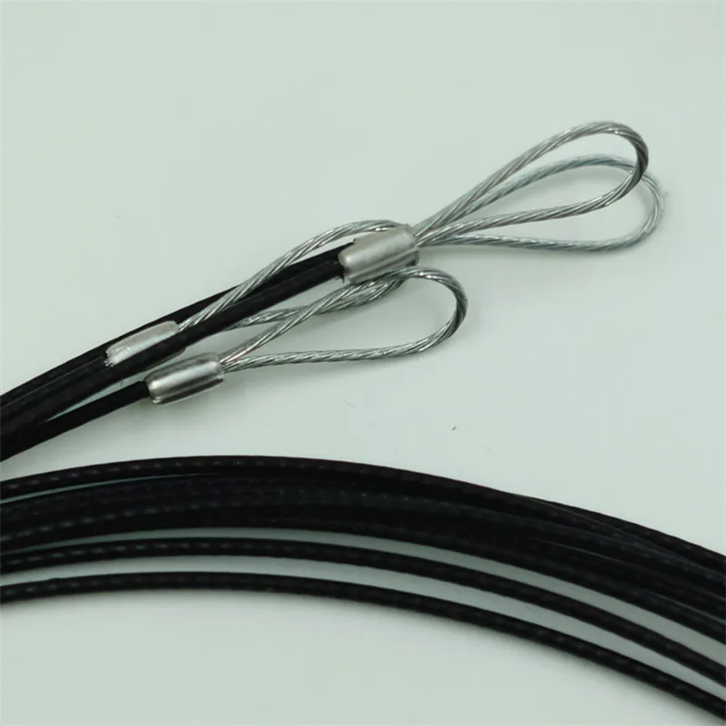
Wire rope forms an important part of many machines and structures. It is comprised of continuous wire strands wound around a central core. There are many kinds of wire rope designed for different applications. Most of them are steel wires made into strands wound with each other. The core can be made of steel, rope or even plastics.
Wire ropes (cables) are identified by several parameters including size, grade of steel used, whether or not it is preformed, by its lay, the number of strands and the number of wires in each strand.
A typical strand and wire designation is 6x19. This denotes a rope made up of six strands with 19 wires in each strand. Different strand sizes and arrangements allow for varying degrees of rope flexibility and resistance to crushing and abrasion. Small wires are better suited to being bent sharply over small sheaves (pulleys). Large outer wires are preferred when the cable will be rubbed or dragged through abrasives.
There are three types of cores. An independent wire rope core (IWRC) is normally a 6x7 wire rope with a 1x7 wire strand core resulting in a 7x7 wire rope. IWRCs have a higher tensile and bending breaking strength than a fiber core rope and a high resistance to crushing and deformation.
A wire strand core (WSC) rope has a single wire strand as its core instead of a multistrand wire rope core. WSC ropes are high strength and are mostly used as static or standing ropes.
Wire ropes also have fiber cores. Fiber core ropes were traditionally made with sisal rope, but may also use plastic materials. The fiber core ropes have less strength than steel core ropes. Fiber core ropes are quite flexible and are used in many overhead crane applications.
The lay of a wire rope is the direction that the wire strands and the strands in the cable twist. There are four common lays: right lay, left lay, regular lay and lang lay. In a right lay rope the strands twist to the right as it winds away from the observer. A left lay twists to the left. A regular lay rope has the wires in the strands twisted in the opposite direction from the strands of the cable. In a lang lay rope, the twist of the strands and the wires in the strands are both twisted the same way. Lang lay ropes are said to have better fatigue resistance due to the flatter exposure of the wires.
Wire ropes are made mostly from high carbon steel for strength, versatility, resilience and availability and for cost consideration. Wire ropes can be uncoated or galvanized. Several grades of steel are used and are described in Table 1.
Steel cable wire is stiff and springy. In nonpreformed rope construction, broken or cut wires will straighten and stick out of the rope as a burr, posing a safety hazard. A preformed cable is made of wires that are shaped so that they lie naturally in their position in the strand, preventing the wires from protruding and potentially causing injury. Preformed wire ropes also have better fatigue resistance than nonpreformed ropes and are ideal for working over small sheaves and around sharp angles.
Lubricating wire ropes is a difficult proposition, regardless of the construction and composition. Ropes with fiber cores are somewhat easier to lubricate than those made exclusively from steel materials. For this reason, it is important to carefully consider the issue of field relubrication when selecting rope for an application.
There are two types of wire rope lubricants, penetrating and coating. Penetrating lubricants contain a petroleum solvent that carries the lubricant into the core of the wire rope then evaporates, leaving behind a heavy lubricating film to protect and lubricate each strand (Figure 2). Coating lubricants penetrate slightly, sealing the outside of the cable from moisture and reducing wear and fretting corrosion from contact with external bodies.
Both types of wire rope lubricants are used. But because most wire ropes fail from the inside, it is important to make sure that the center core receives sufficient lubricant. A combination approach in which a penetrating lubricant is used to saturate the core, followed with a coating to seal and protect the outer surface, is recommended. Wire rope lubricants can be petrolatum, asphaltic, grease, petroleum oils or vegetable oil-based (Figure 3).
Petrolatum compounds, with the proper additives, provide excellent corrosion and water resistance. In addition, petrolatum compounds are translucent, allowing the technician to perform visible inspection. Petrolatum lubricants can drip off at higher temperatures but maintain their consistency well under cold temperature conditions.
Various types of greases are used for wire rope lubrication. These are the coating types that penetrate partially but usually do not saturate the rope core. Common grease thickeners include sodium, lithium, lithium complex and aluminum complex soaps. Greases used for this application generally have a soft semifluid consistency. They coat and achieve partial penetration if applied with pressure lubricators.
Petroleum and vegetable oils penetrate best and are the easiest to apply because proper additive design of these penetrating types gives them excellent wear and corrosion resistance. The fluid property of oil type lubricants helps to wash the rope to remove abrasive external contaminants.
Wire ropes are lubricated during the manufacturing process. If the rope has a fiber core center, the fiber will be lubricated with a mineral oil or petrolatum type lubricant. The core will absorb the lubricant and function as a reservoir for prolonged lubrication while in service.
If the rope has a steel core, the lubricant (both oil and grease type) is pumped in a stream just ahead of the die that twists the wires into a strand. This allows complete coverage of all wires.
After the cable is put into service, relubrication is required due to loss of the original lubricant from loading, bending and stretching of the cable. The fiber core cables dry out over time due to heat from evaporation, and often absorb moisture. Field relubrication is necessary to minimize corrosion, protect and preserve the rope core and wires, and thus extend the service life of the wire rope.
If a cable is dirty or has accumulated layers of hardened lubricant or other contaminants, it must be cleaned with a wire brush and petroleum solvent, compressed air or steam cleaner before relubrication. The wire rope must then be dried and lubricated immediately to prevent rusting. Field lubricants can be applied by spray, brush, dip, drip or pressure boot. Lubricants are best applied at a drum or sheave where the rope strands have a tendency to separate slightly due to bending to facilitate maximum penetration to the core. If a pressure boot application is used, the lubricant is applied to the rope under slight tension in a straight condition. Excessive lubricant application should be avoided to prevent safety hazards.
Some key performance attributes to look for in a wire rope lubricant are wear resistance and corrosion prevention. Some useful performance benchmarks include high four-ball EP test values, such as a weld point (ASTM D2783) of above 350 kg and a load wear index of above 50. For corrosion protection, look for wire rope lubricants with salt spray (ASTM B117) resistance values above 60 hours and humidity cabinet (ASTM D1748) values of more than 60 days. Most manufacturers provide this type of data on product data sheets.
Cable life cycle and performance are influenced by several factors, including type of operation, care and environment. Cables can be damaged by worn sheaves, improper winding and splicing practices, and improper storage. High stress loading, shock loading, jerking heavy loads or rapid acceleration or deceleration (speed of the cable stopping and starting) will accelerate the wear rate.
Corrosion can cause shortened rope life due to metal loss, pitting and stress risers from pitting. If a machine is to be shut down for an extended period, the cables should be removed, cleaned, lubricated and properly stored. In service, corrosion and oxidation are caused by fumes, acids, salt brines, sulfur, gases, salt air, humidity and are accelerated by elevated temperatures. Proper and adequate lubricant application in the field can reduce corrosive attack of the cable.
Abrasive wear occurs on the inside and outside of wire ropes. Individual strands inside the rope move and rub against one another during normal operation, creating internal two-body abrasive wear. The outside of the cable accumulates dirt and contaminants from sheaves and drums. This causes three-body abrasive wear, which erodes the outer wires and strands. Abrasive wear usually reduces rope diameter and can result in core failure and internal wire breakage. Penetrating wire rope lubricants reduce abrasive wear inside the rope and also wash off the external surfaces to remove contaminants and dirt.
Many types of machines and structures use wire ropes, including draglines, cranes, elevators, shovels, drilling rigs, suspension bridges and cable-stayed towers. Each application has specific needs for the type and size of wire rope required. All wire ropes, regardless of the application, will perform at a higher level, last longer and provide greater user benefits when properly maintained.
Lubrication Engineers, Inc. has found through years of field experience, that longer wire rope life can be obtained through the use of penetrating lubricants, either alone or when used in conjunction with a coating lubricant. Practical experience at a South African mine suggests that life cycles may be doubled with this approach. At one mine site, the replacement rate for four 44-mm ropes was extended from an average 18.5 months to 43 months. At another mine, life cycles of four 43-mm x 2073 meter ropes were extended from an average 8 months to 12 months.
In another study involving 5-ton and 10-ton overhead cranes in the United States that used 3/8-inch and 5/8-inch diameter ropes, the average life of the ropes was doubled. The authors attribute this increased performance to the ability of the penetrating lubricant to displace water and contaminants while replacing them with oil, which reduces the wear and corrosion occurring throughout the rope. A good spray with penetrating wire rope lubricant effectively acts as an oil change for wire ropes.
In these examples, the savings in wire rope replacement costs (downtime, labor and capital costs) were substantial and dwarfed the cost of the lubricants. Companies who have realized the importance of proper wire rope lubrication have gained a huge advantage over those who purchase the lowest priced lubricant, or no lubricant at all, while replacing ropes on a much more frequent basis.
In stricter senses, the term wire rope refers to a diameter larger than 9.5mm (3⁄8in), with smaller gauges designated cable or cords.wrought iron wires were used, but today steel is the main material used for wire ropes.
Historically, wire rope evolved from wrought iron chains, which had a record of mechanical failure. While flaws in chain links or solid steel bars can lead to catastrophic failure, flaws in the wires making up a steel cable are less critical as the other wires easily take up the load. While friction between the individual wires and strands causes wear over the life of the rope, it also helps to compensate for minor failures in the short run.
Wire ropes were developed starting with mining hoist applications in the 1830s. Wire ropes are used dynamically for lifting and hoisting in cranes and elevators, and for transmission of mechanical power. Wire rope is also used to transmit force in mechanisms, such as a Bowden cable or the control surfaces of an airplane connected to levers and pedals in the cockpit. Only aircraft cables have WSC (wire strand core). Also, aircraft cables are available in smaller diameters than wire rope. For example, aircraft cables are available in 1.2mm (3⁄64in) diameter while most wire ropes begin at a 6.4mm (1⁄4in) diameter.suspension bridges or as guy wires to support towers. An aerial tramway relies on wire rope to support and move cargo overhead.
Maintain a record for each rope that includes the date of inspection, type of inspection, the name of the person who performed the inspection, and inspection results.
Use the "rag-and-visual" method to check for external damage. Grab the rope lightly and with a rag or cotton cloth, move the rag slowly along the wire. Broken wires will often "porcupine" (stick out) and these broken wires will snag on the rag. If the cloth catches, stop and visually assess the rope. It is also important to visually inspect the wire (without a rag). Some wire breaks will not porcupine.
Measure the rope diameter. Compare the rope diameter measurements with the original diameter. If the measurements are different, this change indicates external and/or internal rope damage.
Visually check for abrasions, corrosion, pitting, and lubrication inside the rope. Insert a marlin spike beneath two strands and rotate to lift strands and open rope.
Assess the condition of the rope at the section showing the most wear. Discard a wire rope if you find any of the following conditions:In running ropes (wound on drums or passed over sheaves), 6 or more broken wires in one rope lay length; 3 or more broken wires in one strand in one rope lay. (One rope lay is the distance necessary to complete one turn of the strand around the diameter of the rope.)
Corrosion from lack of lubrication and exposure to heat or moisture (e.g., wire rope shows signs of pitting). A fibre core rope will dry out and break at temperatures above 120°C (250°F).
Kinks from the improper installation of new rope, the sudden release of a load or knots made to shorten a rope. A kink cannot be removed without creating a weak section. Discarding kinked rope is best.


 8613371530291