
wire rope cad drawings made in china
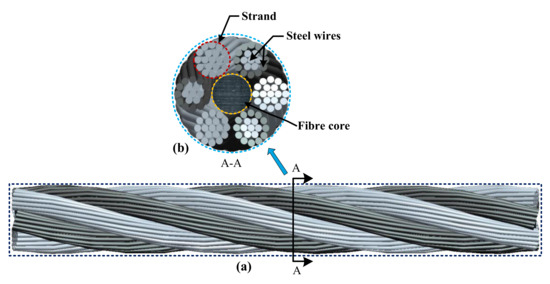
Wire rope consists of several strands of metal wire laid (twisted) into a helix. The term "cable" is often used interchangeably with "wire rope", but narrower senses exist in which "wire rope" refers to diameter larger than 3/8 inch (9.52 mm), whereas sizes smaller than this are designated cable or cords.wrought iron wires were used, but today steel is the main material used for wire ropes.
Historically wire rope evolved from wrought iron chains, which had a record of mechanical failure. While flaws in chain links or solid steel bars can lead to catastrophic failure, flaws in the wires making up a steel cable are less critical as the other wires easily take up the load. Friction between the individual wires and strands, as a consequence of their twist, further compensates for any flaws.
Wire ropes were developed starting with mining hoist applications in the 1830s. Wire ropes are used dynamically for lifting and hoisting in cranes and elevators, and for transmission of mechanical power. Wire rope is also used to transmit force in mechanisms, such as a Bowden cable or the control surfaces of an airplane connected to levers and pedals in the cockpit. Only aircraft cables have WSC (wire strand core). Also, aircraft cables are available in smaller diameters than wire rope. For example, aircraft cables are available in 3/64 in. diameter while most wire ropes begin at a 1/4 in. diameter.suspension bridges or as guy wires to support towers. An aerial tramway relies on wire rope to support and move cargo overhead.
Modern wire rope was invented by the German mining engineer Wilhelm Albert in the years between 1831 and 1834 for use in mining in the Harz Mountains in Clausthal, Lower Saxony, Germany.chains, such as had been used before.
Wilhelm Albert"s first ropes consisted of three strands consisting of four wires each. In 1840, Scotsman Robert Stirling Newall improved the process further.John A. Roebling, starting in 1841 suspension bridge building. Roebling introduced a number of innovations in the design, materials and manufacture of wire rope. Ever with an ear to technology developments in mining and railroading, Josiah White and Erskine Hazard, principal ownersLehigh Coal & Navigation Company (LC&N Co.) — as they had with the first blast furnaces in the Lehigh Valley — built a Wire Rope factory in Mauch Chunk,Pennsylvania in 1848, which provided lift cables for the Ashley Planes project, then the back track planes of the Summit Hill & Mauch Chunk Railroad, improving its attractiveness as a premier tourism destination, and vastly improving the throughput of the coal capacity since return of cars dropped from nearly four hours to less than 20 minutes. The decades were witness to a burgeoning increase in deep shaft mining in both Europe and North America as surface mineral deposits were exhausted and miner had to chase layers along inclined layers. The era was early in railroad development and steam engines having sufficient tractive effort to climb steep slopes were in the future, so incline plane railways were common, and the mining tunnels along inclined shafts between coal layers were just a which came first variant, but where steam engines could not go. This pushed development of cable hoists rapidly in the United States as surface deposits in the Anthracite Coal Region north and south dove deeper every year, and even the rich deposits in the Panther Creek Valley required LC&N Co. to drive their first shafts into lower slopes beginning Lansford and its Schuylkill County twin-town Coaldale.
The German engineering firm of Adolf Bleichert & Co. was founded in 1874 and began to build bicable aerial tramways for mining in the Ruhr Valley. With important patents, and dozens of working systems in Europe, Bleichert dominated the global industry, later licensing its designs and manufacturing techniques to Trenton Iron Works, New Jersey, USA which built systems across America. Adolf Bleichert & Co. went on to build hundreds of aerial tramways around the world: from Alaska to Argentina, Australia and Spitsbergen. The Bleichert company also built hundreds of aerial tramways for both the Imperial German Army and the Wehrmacht.
In the last half of the 19th century, wire rope systems were used as a means of transmitting mechanical powercable cars. Wire rope systems cost one-tenth as much and had lower friction losses than line shafts. Because of these advantages, wire rope systems were used to transmit power for a distance of a few miles or kilometers.
Steel wires for wire ropes are normally made of non-alloy carbon steel with a carbon content of 0.4 to 0.95%. The very high strength of the rope wires enables wire ropes to support large tensile forces and to run over sheaves with relatively small diameters.
In the mostly used parallel lay strands, the lay length of all the wire layers is equal and the wires of any two superimposed layers are parallel, resulting in linear contact. The wire of the outer layer is supported by two wires of the inner layer. These wires are neighbours along the whole length of the strand. Parallel lay strands are made in one operation. The endurance of wire ropes with this kind of strand is always much greater than of those (seldom used) with cross lay strands. Parallel lay strands with two wire layers have the construction Filler, Seale or Warrington.
In principle, spiral ropes are round strands as they have an assembly of layers of wires laid helically over a centre with at least one layer of wires being laid in the opposite direction to that of the outer layer. Spiral ropes can be dimensioned in such a way that they are non-rotating which means that under tension the rope torque is nearly zero.
The open spiral rope consists only of round wires. The half-locked coil rope and the full-locked coil rope always have a centre made of round wires. The locked coil ropes have one or more outer layers of profile wires. They have the advantage that their construction prevents the penetration of dirt and water to a greater extent and it also protects them from loss of lubricant. In addition, they have one further very important advantage as the ends of a broken outer wire cannot leave the rope if it has the proper dimensions.
Stranded ropes are an assembly of several strands laid helically in one or more layers around a core. This core can be one of three types. The first is a fiber core, made up of synthetic material or natural fibers like Sysal. Synthetic fibers are stronger and more uniform but can"t absorb much lubricant. Natural fibers can absorb up to 15% of their weight in lubricant and so protect the inner wires much better from corrosion than synthetic fibers do. Fiber cores are the most flexible and elastic, but have the downside of getting crushed easily. The second type, wire strand core, is made up of one additional strand of wire, and is typically used for suspension. The third type is independent wire rope core (IWRC), which is the most durable in all types of environments.ordinary lay rope if the lay direction of the wires in the outer strands is in the opposite direction to the lay of the outer strands themselves. If both the wires in the outer strands and the outer strands themselves have the same lay direction, the rope is called a lang lay rope (formerly Albert’s lay or Lang’s lay). Regular lay means the individual wires were wrapped around the centers in one direction and the strands were wrapped around the core in the opposite direction.
Multi-strand ropes are all more or less resistant to rotation and have at least two layers of strands laid helically around a centre. The direction of the outer strands is opposite to that of the underlying strand layers. Ropes with three strand layers can be nearly non-rotating. Ropes with two strand layers are mostly only low-rotating.
Stationary ropes, stay ropes (spiral ropes, mostly full-locked) have to carry tensile forces and are therefore mainly loaded by static and fluctuating tensile stresses. Ropes used for suspension are often called cables.
Track ropes (full locked ropes) have to act as rails for the rollers of cabins or other loads in aerial ropeways and cable cranes. In contrast to running ropes, track ropes do not take on the curvature of the rollers. Under the roller force, a so-called free bending radius of the rope occurs. This radius increases (and the bending stresses decrease) with the tensile force and decreases with the roller force.
Wire rope slings (stranded ropes) are used to harness various kinds of goods. These slings are stressed by the tensile forces but first of all by bending stresses when bent over the more or less sharp edges of the goods.
There are technical regulations for the rope drives of cranes, elevators, rope ways and mining installations not exceeding a given tensile force and not falling short of a given diameter ratio D/d of sheave and rope diameters. A general dimensioning method of rope drives (and used besides the technical regulations) calculate the five limits
Donandt force (yielding tensile force for a given bending diameter ratio D/d) - strict limit. The nominal rope tensile force S must be smaller than the Donandt force SD1.
Rope safety factor = minimum breaking force Fmin / nominal rope tensile force S. (ability to resist extreme impact forces) - Fmin/S ≥ 2,5 for simple lifting appliance
Discarding number of wire breaks (detection to need rope replacement) Minimum number of wire breaks on a reference rope length of 30d should be BA30 ≥ 8 for lifting appliance
Optimal rope diameter with the max. rope endurance for a given sheave diameter D and tensile rope force S - For economic reasons the rope diameter should be near to but smaller than the optimal rope diameter d ≤ dopt.
The wire ropes are stressed by fluctuating forces, by wear, by corrosion and in seldom cases by extreme forces. The rope life is finite and the safety is only ensured by inspection for the detection of wire breaks on a reference rope length, of cross-section loss, as well as other failures so that the wire rope can be replaced before a dangerous situation occurs. Installations should be designed to facilitate the inspection of the wire ropes.
Lifting installations for passenger transportation require that a combination of several methods should be used to prevent a car from plunging downwards. Elevators must have redundant bearing ropes and a safety gear. Ropeways and mine hoistings must be permanently supervised by a responsible manager and the rope must be inspected by a magnetic method capable of detecting inner wire breaks.
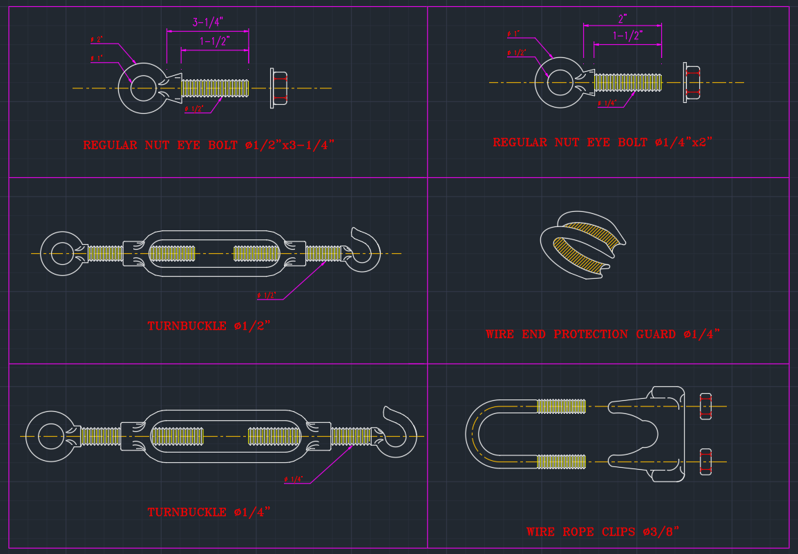
The end of a wire rope tends to fray readily, and cannot be easily connected to plant and equipment. There are different ways of securing the ends of wire ropes to prevent fraying. The most common and useful type of end fitting for a wire rope is to turn the end back to form a loop. The loose end is then fixed back on the wire rope. Termination efficiencies vary from about 70% for a Flemish eye alone; to nearly 90% for a Flemish eye and splice; to 100% for potted ends and swagings.
When the wire rope is terminated with a loop, there is a risk that it will bend too tightly, especially when the loop is connected to a device that concentrates the load on a relatively small area. A thimble can be installed inside the loop to preserve the natural shape of the loop, and protect the cable from pinching and abrading on the inside of the loop. The use of thimbles in loops is industry best practice. The thimble prevents the load from coming into direct contact with the wires.
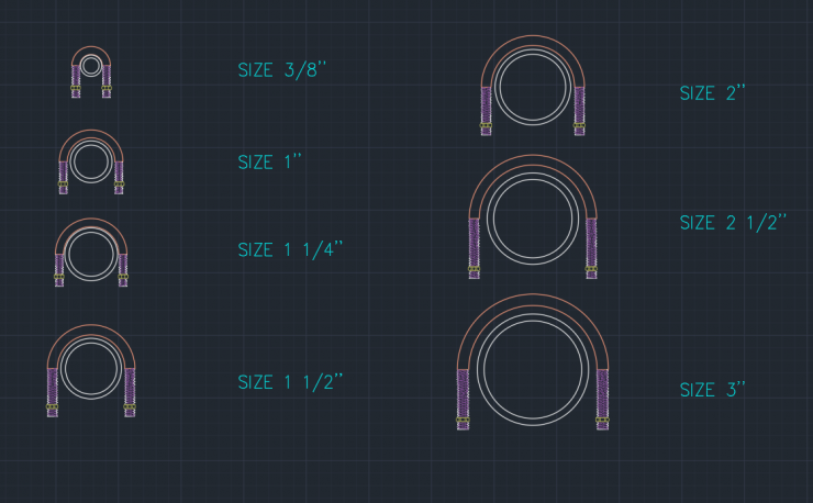
A wire rope clamp, also called a clip, is used to fix the loose end of the loop back to the wire rope. It usually consists of a U-shaped bolt, a forged saddle, and two nuts. The two layers of wire rope are placed in the U-bolt. The saddle is then fitted over the ropes on to the bolt (the saddle includes two holes to fit to the u-bolt). The nuts secure the arrangement in place. Three or more clamps are usually used to terminate a wire rope. As many as eight may be needed for a 2 in (50.8 mm) diameter rope.
There is an old adage; be sure not to "saddle a dead horse." This means that when installing clamps, the saddle portion of the clamp assembly is placed on the load-bearing or "live" side, not on the non-load-bearing or "dead" side of the cable. According to the US Navy Manual S9086-UU-STM-010, Chapter 613R3, Wire and Fiber rope and Rigging, "This is to protect the live or stress-bearing end of the rope against crushing and abuse. The flat bearing seat and extended prongs of the body (saddle) are designed to protect the rope and are always placed against the live end."
An eye splice may be used to terminate the loose end of a wire rope when forming a loop. The strands of the end of a wire rope are unwound a certain distance, and plaited back into the wire rope, forming the loop, or an eye, called an eye splice. When this type of rope splice is used specifically on wire rope, it is called a "Molly Hogan", and, by some, a "Dutch" eye instead of a "Flemish" eye.
Swaging is a method of wire rope termination that refers to the installation technique. The purpose of swaging wire rope fittings is to connect two wire rope ends together, or to otherwise terminate one end of wire rope to something else. A mechanical or hydraulic swager is used to compress and deform the fitting, creating a permanent connection. There are many types of swaged fittings. Threaded Studs, Ferrules, Sockets, and Sleeves are a few examples.
A wedge socket termination is useful when the fitting needs to be replaced frequently. For example, if the end of a wire rope is in a high-wear region, the rope may be periodically trimmed, requiring the termination hardware to be removed and reapplied. An example of this is on the ends of the drag ropes on a dragline. The end loop of the wire rope enters a tapered opening in the socket, wrapped around a separate component called the wedge. The arrangement is knocked in place, and load gradually eased onto the rope. As the load increases on the wire rope, the wedge become more secure, gripping the rope tighter.
Poured sockets are used to make a high strength, permanent termination; they are created by inserting the wire rope into the narrow end of a conical cavity which is oriented in-line with the intended direction of strain. The individual wires are splayed out inside the cone or "capel", and the cone is then filled with molten lead-antimony-tin (Pb80Sb15Sn5) solder or "white metal capping",zincpolyester resin compound.

E. Stanova, G. Fedorko, M. Fabian and S. Kmet, Computer modelling of wire strands and ropes part I: theory and computer implementation, Advances in Engineering Software, 42(6) (2011) 305–315.
D. G. Wang, D. K. Zhang, S. Q. Wang and S. R. Ge, Finite element analysis of hoisting rope and fretting wear evolution and fatigue life estimation of steel wires, Engineering Failure Analysis, 27 (2013) 173–193.
D. G. Wang, X. W. Li, X. R. Wang, G. Y. Shi, X. B. Mao and D. A. Wang, Effects of hoisting parameters on dynamic contact characteristics between the rope and friction lining in a deep coal mine, Tribology International, 96 (2016) 31–42.
S. Lalonde, R. Guilbault and F. Légeron, Modeling multilayered wire strands, a strategy based on 3D finite element beam-to-beam contacts-part I: model formulation and validation, International Journal of Mechanical Sciences, 126 (2017) 281–296.
X. Cao and W. G. Wu, The establishment of a mechanics model of multi-strand wire rope subjected to bending load with finite element simulation and experimental verification, International Journal of Mechanical Sciences, 142 (2018) 289–303.
E. Stanova, G. Fedorko, M. Fabian and S. Kmet, Computer modelling of wire strands and ropes part II: finite element-based applications, Advances in Engineering Software, 42(6) (2011) 322–331.
C. Erdönmez and C. E. Imrak, New approaches for model generation and analysis for wire rope, International Conference on Computational Science and Its Applications (2011) 103–111.
C. Erdönmez and C. E. Imrak, A finite element model for independent wire rope core with double helical geometry subjected to axial loads, Sadhana, 36(6) (2011) 995–1008.
P. Zhang, M. L. Duan, J. M. Ma and Y. Zhang, A precise mathematical model for geometric modeling of wire rope strands structure, Applied Mathematical Modelling, 76 (2019) 151–171.
G. Wang, R. Zhao, J. Sun and H. Zhang, CAD of wire rope structure based on the differential geometry, Journal of Huazhong University of Science and Technology, 31(6) (2003) 3–6.
W. Ma, Z. C. Zhu, Y. X. Peng and G. A. Chen, Computer-aided modeling of wire ropes bent over a sheave, Advances in Engineering Software, 90 (2015) 11–21.
W. Zhang, W. Guo, C. W. Zhang, Z. X. Lu and X. B. Xu, Research on wire rope stress distribution of WR-CVT, Materials Science and Engineering, 241 (2017) 12–14.
W. Zhang, X. Q. Zhang, C. W. Zhang and J. F. Zhang, Theory and implementation of no-joint wire rope spatial geometry modeling, Mathematical Problems in Engineering (2019) 1–11.
W. Zhang, X. Q. Zhang, C. W. Zhang, Z. X. Lu and J. F. Zhang, Geometric modeling theory and 3D solid implementation of closed wire rope on Pro/E, Journal of the Brazilian Society of Mechanical Sciences and Engineering, 42(8) (2020) 1–9.
X. Y. Wang, X. B. Meng, J. X. Wang, Y. H. Sun and K. Gao, Mathematical modeling and geometric analysis for wire rope strands, Applied Mathematical Modelling, 39(3–4) (2015) 1019–1032.

Bridge construction scaffolding joints cad drawing details that includes a detailed view of detail of the remate (above alero), parapet detail, detail of the parapet and the gar…
★【Over 500+ Types of Steel Structure CAD Details Bundle】Structural Metal Framing Structural Steel Framing Wire Rope Assemblies Steel Joist Framing Metal Decking Cold-Formed Meta…

Verify that the file storage location is working properly. If cloud storage is where the error comes from, reinstall the cloud drive. Some storage solutions offer on-demand access. Disable this option or download local copies of one or more files and check whether they open correctly.

This product is part of the XY2C range, an offer of emergency stop rope pull switches. This dual emergency stop rope pull switch has 2 x (1 normally closed + 1 normally opened) slow-break contacts with positive opening operation. It is a switch with a rated operational current of 0.27A at 250V AC, 3A at 240V AC and a conventional enclosed thermal current of 10A. It is furnished with screw clamp terminals for electrical connection and 3 tapped entry for 1/2inch NPT conduit entry. The trigger cable anchor point at left hand and right hand side. It can reset by flush pushbutton. It offers long mechanical durability which is about 60000 operating cycles. It is an IP66 rated product. The casing is made of Zamak (red) with stainless steel cover. Its dimensions are 327mm (Width) x 106mm (Depth) x 142mm (Height) and weighs 1.9kg. It is intended for all machine applications like woodworking machines, shears, conveyor systems, printing machines, textile machines, rolling mills, test laboratories, paint shops, surface treatment works, etc. This product is certified by CCC, CSA, EAC and UL. It meets CSA C22.2 No 14, EN/ISO 13850, EN/IEC 60947-5-1, EN/IEC 60204-1, EN/IEC 60947-5-5, UL 508 Machinery directive 2006/42/EC and Work equipment directive 2009/104/EC standards. These emergency stop rope pull switches can be equipped with trip indicators and double anchor points. The emergency stop rope pull switch is intended for all machines requiring stopping of dangerous movement in the immediate vicinity of the machine. These emergency stop rope pull switches are essential in premises and on machines that pose a potential hazard during operation. Operators must be able to activate the emergency stop from any point within their work area.
Loos Naples is the recognized leader in the field of MilSpec hardware and wire rope fittings. 60 years ago we pioneered this industry. It is with that same innovative spirit that we have launched Loos Precision Products (LPP). Loos Precision Products offers its capabilities to produce build-to-print parts for mid- to high-volume production.
Our manufacturing capabilities consist of CNC Swiss lathes, Y-axis lathes, 4-axis vertical milling centers, thread roller machines, broaching, and in-house passivation. We use the latest SolidWorks/SolidCAM CAD/CAM software to ensure efficient and seamless incorporation of your designs, no matter what type of design file you have. Our shop has experience machining all types of ferrous and nonferrous material, including stainless steels, carbon steels, brass, aluminum, and exotic metals such as titanium.


 8613371530291