
wire rope cad drawings price

The Computer-Aided Design ("CAD") files and all associated content posted to this website are created, uploaded, managed and owned by third-party users. Each CAD and any associated text, image or data is in no way sponsored by or affiliated with any company, organization or real-world item, product, or good it may purport to portray.
The Computer-Aided Design ("CAD") files and all associated content posted to this website are created, uploaded, managed and owned by third-party users. Each CAD and any associated text, image or data is in no way sponsored by or affiliated with any company, organization or real-world item, product, or good it may purport to portray.

Wire rope consists of several strands of metal wire laid (twisted) into a helix. The term "cable" is often used interchangeably with "wire rope", but narrower senses exist in which "wire rope" refers to diameter larger than 3/8 inch (9.52 mm), whereas sizes smaller than this are designated cable or cords.wrought iron wires were used, but today steel is the main material used for wire ropes.
Historically wire rope evolved from wrought iron chains, which had a record of mechanical failure. While flaws in chain links or solid steel bars can lead to catastrophic failure, flaws in the wires making up a steel cable are less critical as the other wires easily take up the load. Friction between the individual wires and strands, as a consequence of their twist, further compensates for any flaws.
Wire ropes were developed starting with mining hoist applications in the 1830s. Wire ropes are used dynamically for lifting and hoisting in cranes and elevators, and for transmission of mechanical power. Wire rope is also used to transmit force in mechanisms, such as a Bowden cable or the control surfaces of an airplane connected to levers and pedals in the cockpit. Only aircraft cables have WSC (wire strand core). Also, aircraft cables are available in smaller diameters than wire rope. For example, aircraft cables are available in 3/64 in. diameter while most wire ropes begin at a 1/4 in. diameter.suspension bridges or as guy wires to support towers. An aerial tramway relies on wire rope to support and move cargo overhead.
Modern wire rope was invented by the German mining engineer Wilhelm Albert in the years between 1831 and 1834 for use in mining in the Harz Mountains in Clausthal, Lower Saxony, Germany.chains, such as had been used before.
Wilhelm Albert"s first ropes consisted of three strands consisting of four wires each. In 1840, Scotsman Robert Stirling Newall improved the process further.John A. Roebling, starting in 1841 suspension bridge building. Roebling introduced a number of innovations in the design, materials and manufacture of wire rope. Ever with an ear to technology developments in mining and railroading, Josiah White and Erskine Hazard, principal ownersLehigh Coal & Navigation Company (LC&N Co.) — as they had with the first blast furnaces in the Lehigh Valley — built a Wire Rope factory in Mauch Chunk,Pennsylvania in 1848, which provided lift cables for the Ashley Planes project, then the back track planes of the Summit Hill & Mauch Chunk Railroad, improving its attractiveness as a premier tourism destination, and vastly improving the throughput of the coal capacity since return of cars dropped from nearly four hours to less than 20 minutes. The decades were witness to a burgeoning increase in deep shaft mining in both Europe and North America as surface mineral deposits were exhausted and miner had to chase layers along inclined layers. The era was early in railroad development and steam engines having sufficient tractive effort to climb steep slopes were in the future, so incline plane railways were common, and the mining tunnels along inclined shafts between coal layers were just a which came first variant, but where steam engines could not go. This pushed development of cable hoists rapidly in the United States as surface deposits in the Anthracite Coal Region north and south dove deeper every year, and even the rich deposits in the Panther Creek Valley required LC&N Co. to drive their first shafts into lower slopes beginning Lansford and its Schuylkill County twin-town Coaldale.
The German engineering firm of Adolf Bleichert & Co. was founded in 1874 and began to build bicable aerial tramways for mining in the Ruhr Valley. With important patents, and dozens of working systems in Europe, Bleichert dominated the global industry, later licensing its designs and manufacturing techniques to Trenton Iron Works, New Jersey, USA which built systems across America. Adolf Bleichert & Co. went on to build hundreds of aerial tramways around the world: from Alaska to Argentina, Australia and Spitsbergen. The Bleichert company also built hundreds of aerial tramways for both the Imperial German Army and the Wehrmacht.
In the last half of the 19th century, wire rope systems were used as a means of transmitting mechanical powercable cars. Wire rope systems cost one-tenth as much and had lower friction losses than line shafts. Because of these advantages, wire rope systems were used to transmit power for a distance of a few miles or kilometers.
Steel wires for wire ropes are normally made of non-alloy carbon steel with a carbon content of 0.4 to 0.95%. The very high strength of the rope wires enables wire ropes to support large tensile forces and to run over sheaves with relatively small diameters.
In the mostly used parallel lay strands, the lay length of all the wire layers is equal and the wires of any two superimposed layers are parallel, resulting in linear contact. The wire of the outer layer is supported by two wires of the inner layer. These wires are neighbours along the whole length of the strand. Parallel lay strands are made in one operation. The endurance of wire ropes with this kind of strand is always much greater than of those (seldom used) with cross lay strands. Parallel lay strands with two wire layers have the construction Filler, Seale or Warrington.
In principle, spiral ropes are round strands as they have an assembly of layers of wires laid helically over a centre with at least one layer of wires being laid in the opposite direction to that of the outer layer. Spiral ropes can be dimensioned in such a way that they are non-rotating which means that under tension the rope torque is nearly zero.
The open spiral rope consists only of round wires. The half-locked coil rope and the full-locked coil rope always have a centre made of round wires. The locked coil ropes have one or more outer layers of profile wires. They have the advantage that their construction prevents the penetration of dirt and water to a greater extent and it also protects them from loss of lubricant. In addition, they have one further very important advantage as the ends of a broken outer wire cannot leave the rope if it has the proper dimensions.
Stranded ropes are an assembly of several strands laid helically in one or more layers around a core. This core can be one of three types. The first is a fiber core, made up of synthetic material or natural fibers like Sysal. Synthetic fibers are stronger and more uniform but can"t absorb much lubricant. Natural fibers can absorb up to 15% of their weight in lubricant and so protect the inner wires much better from corrosion than synthetic fibers do. Fiber cores are the most flexible and elastic, but have the downside of getting crushed easily. The second type, wire strand core, is made up of one additional strand of wire, and is typically used for suspension. The third type is independent wire rope core (IWRC), which is the most durable in all types of environments.ordinary lay rope if the lay direction of the wires in the outer strands is in the opposite direction to the lay of the outer strands themselves. If both the wires in the outer strands and the outer strands themselves have the same lay direction, the rope is called a lang lay rope (formerly Albert’s lay or Lang’s lay). Regular lay means the individual wires were wrapped around the centers in one direction and the strands were wrapped around the core in the opposite direction.
Multi-strand ropes are all more or less resistant to rotation and have at least two layers of strands laid helically around a centre. The direction of the outer strands is opposite to that of the underlying strand layers. Ropes with three strand layers can be nearly non-rotating. Ropes with two strand layers are mostly only low-rotating.
Stationary ropes, stay ropes (spiral ropes, mostly full-locked) have to carry tensile forces and are therefore mainly loaded by static and fluctuating tensile stresses. Ropes used for suspension are often called cables.
Track ropes (full locked ropes) have to act as rails for the rollers of cabins or other loads in aerial ropeways and cable cranes. In contrast to running ropes, track ropes do not take on the curvature of the rollers. Under the roller force, a so-called free bending radius of the rope occurs. This radius increases (and the bending stresses decrease) with the tensile force and decreases with the roller force.
Wire rope slings (stranded ropes) are used to harness various kinds of goods. These slings are stressed by the tensile forces but first of all by bending stresses when bent over the more or less sharp edges of the goods.
There are technical regulations for the rope drives of cranes, elevators, rope ways and mining installations not exceeding a given tensile force and not falling short of a given diameter ratio D/d of sheave and rope diameters. A general dimensioning method of rope drives (and used besides the technical regulations) calculate the five limits
Donandt force (yielding tensile force for a given bending diameter ratio D/d) - strict limit. The nominal rope tensile force S must be smaller than the Donandt force SD1.
Rope safety factor = minimum breaking force Fmin / nominal rope tensile force S. (ability to resist extreme impact forces) - Fmin/S ≥ 2,5 for simple lifting appliance
Discarding number of wire breaks (detection to need rope replacement) Minimum number of wire breaks on a reference rope length of 30d should be BA30 ≥ 8 for lifting appliance
Optimal rope diameter with the max. rope endurance for a given sheave diameter D and tensile rope force S - For economic reasons the rope diameter should be near to but smaller than the optimal rope diameter d ≤ dopt.
The wire ropes are stressed by fluctuating forces, by wear, by corrosion and in seldom cases by extreme forces. The rope life is finite and the safety is only ensured by inspection for the detection of wire breaks on a reference rope length, of cross-section loss, as well as other failures so that the wire rope can be replaced before a dangerous situation occurs. Installations should be designed to facilitate the inspection of the wire ropes.
Lifting installations for passenger transportation require that a combination of several methods should be used to prevent a car from plunging downwards. Elevators must have redundant bearing ropes and a safety gear. Ropeways and mine hoistings must be permanently supervised by a responsible manager and the rope must be inspected by a magnetic method capable of detecting inner wire breaks.
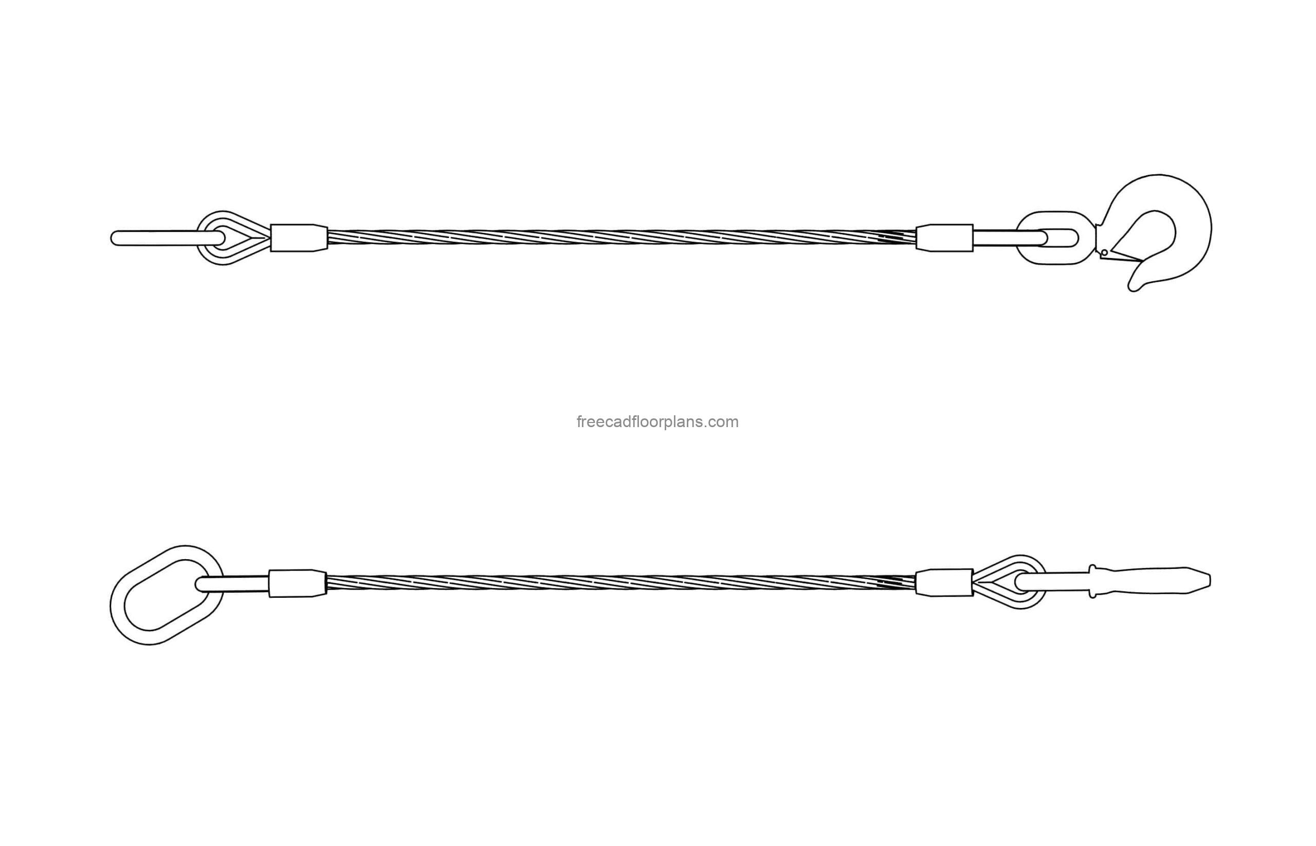
The end of a wire rope tends to fray readily, and cannot be easily connected to plant and equipment. There are different ways of securing the ends of wire ropes to prevent fraying. The most common and useful type of end fitting for a wire rope is to turn the end back to form a loop. The loose end is then fixed back on the wire rope. Termination efficiencies vary from about 70% for a Flemish eye alone; to nearly 90% for a Flemish eye and splice; to 100% for potted ends and swagings.
When the wire rope is terminated with a loop, there is a risk that it will bend too tightly, especially when the loop is connected to a device that concentrates the load on a relatively small area. A thimble can be installed inside the loop to preserve the natural shape of the loop, and protect the cable from pinching and abrading on the inside of the loop. The use of thimbles in loops is industry best practice. The thimble prevents the load from coming into direct contact with the wires.
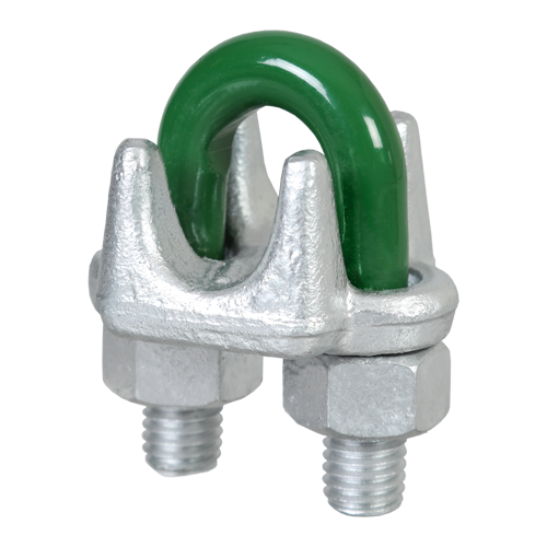
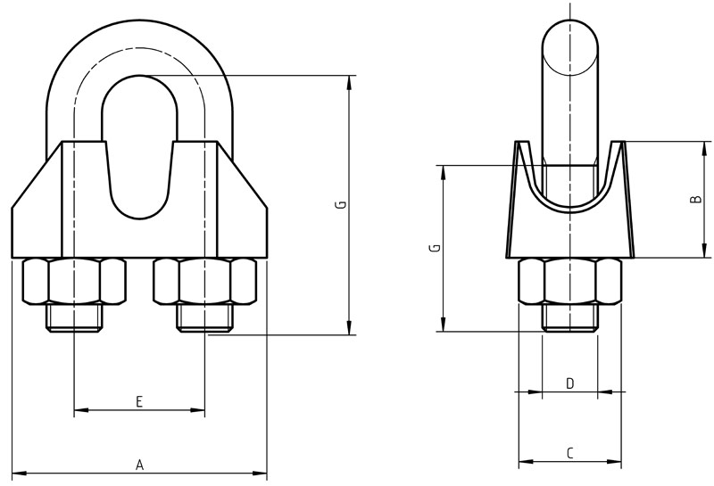
A wire rope clamp, also called a clip, is used to fix the loose end of the loop back to the wire rope. It usually consists of a U-shaped bolt, a forged saddle, and two nuts. The two layers of wire rope are placed in the U-bolt. The saddle is then fitted over the ropes on to the bolt (the saddle includes two holes to fit to the u-bolt). The nuts secure the arrangement in place. Three or more clamps are usually used to terminate a wire rope. As many as eight may be needed for a 2 in (50.8 mm) diameter rope.
There is an old adage; be sure not to "saddle a dead horse." This means that when installing clamps, the saddle portion of the clamp assembly is placed on the load-bearing or "live" side, not on the non-load-bearing or "dead" side of the cable. According to the US Navy Manual S9086-UU-STM-010, Chapter 613R3, Wire and Fiber rope and Rigging, "This is to protect the live or stress-bearing end of the rope against crushing and abuse. The flat bearing seat and extended prongs of the body (saddle) are designed to protect the rope and are always placed against the live end."
An eye splice may be used to terminate the loose end of a wire rope when forming a loop. The strands of the end of a wire rope are unwound a certain distance, and plaited back into the wire rope, forming the loop, or an eye, called an eye splice. When this type of rope splice is used specifically on wire rope, it is called a "Molly Hogan", and, by some, a "Dutch" eye instead of a "Flemish" eye.
Swaging is a method of wire rope termination that refers to the installation technique. The purpose of swaging wire rope fittings is to connect two wire rope ends together, or to otherwise terminate one end of wire rope to something else. A mechanical or hydraulic swager is used to compress and deform the fitting, creating a permanent connection. There are many types of swaged fittings. Threaded Studs, Ferrules, Sockets, and Sleeves are a few examples.
A wedge socket termination is useful when the fitting needs to be replaced frequently. For example, if the end of a wire rope is in a high-wear region, the rope may be periodically trimmed, requiring the termination hardware to be removed and reapplied. An example of this is on the ends of the drag ropes on a dragline. The end loop of the wire rope enters a tapered opening in the socket, wrapped around a separate component called the wedge. The arrangement is knocked in place, and load gradually eased onto the rope. As the load increases on the wire rope, the wedge become more secure, gripping the rope tighter.
Poured sockets are used to make a high strength, permanent termination; they are created by inserting the wire rope into the narrow end of a conical cavity which is oriented in-line with the intended direction of strain. The individual wires are splayed out inside the cone or "capel", and the cone is then filled with molten lead-antimony-tin (Pb80Sb15Sn5) solder or "white metal capping",zincpolyester resin compound.

Browse and download more than 240 separate 3D CAD Models (.stp) by simply going to the website and choosing the specific product and selecting the CAD drawing by clicking on the icon. This easy to use resource enables access to YOKE products when designing lifting arrangements.
YOKE makes this online resource available to engineering teams and riggers who value the ease of use that CAD drawings bring to them, no lengthy registration process, simply at the press of a button. Other formats can be made available upon request.

Proprietary Rights. Crosby retains all ownership right, title, and interest in and to all programs, procedures, information, and documentation associated with the Materials. The Crosby name and all names, logos, and icons identifying Crosby and its products and services are proprietary trademarks of Crosby, and any use of such marks without the express written permission of Crosby is strictly prohibited. Except as expressly provided herein, Crosby does not grant any express or implied right to You or any other person under any intellectual or proprietary rights. Accordingly, unauthorized use of the Materials may violate intellectual property or other proprietary rights laws as well as other domestic and international laws, regulations, and statutes, including, but not limited to, United States copyright, trade secret, patent, and trademark law.
Term and Termination. This License Agreement and Your right to use the Materials will take effect upon the earliest of: (i) delivery of the Materials to You, (ii) at the moment You choose “I ACCEPT” or (iii) You install, download, access, or use the Materials, whichever occurs first, and is effective for a period of forty-eight (48) months unless earlier terminated as set forth below. This License Agreement will terminate automatically if You choose “I REJECT” or if You fail to comply with any of the terms and conditions described herein, including by exceeding the scope of the License. Termination or expiration of this License Agreement will be effective without notice. You may also terminate at any time by ceasing to use the Materials, but all applicable provisions of this Agreement will survive termination, as outlined below. Upon termination or expiration, You must return, destroy, or delete from Your system all copies (including electronic copies) of PowerPoint files and training materials in Your possession. The provisions concerning proprietary and intellectual property rights, submissions, confidentiality, indemnity, disclaimers of warranty and liability, termination, and governing law will survive the termination or expiration of the License Agreement for any reason.
CAD drawings are critical to many different industries. They are used by architectural design services to create detailed blueprints for future buildings, but also for manufacturing and other equipment that requires drafting to be successfully built.
Before CAD software was available, blueprints and schematics for manufacturing were entirely drawn by hand. This was an expensive undertaking that required a full team of drafters to complete, but thanks to this software, only one drafter is usually needed.
If you have a new apartment design you want built, or a complex product you want to be brought into the world, you may need to utilize CAD drawing services to be successful.
Several different factors will change the cost of CAD drawing services, but in general, you can expect them to run between $100 and $150 per hour. Some drafters offer lower prices due to lack of experience, while higher prices may be due to someone’s high qualifications.
CAD artists are generally known for their realistic 3D renders. Yet freelance 2D drawing and floor plan designers also have an important role in architecture and product creation.
An artist who has developed their education more will have higher prices than someone who has little to no education. CAD drafting services generally have at least an associate’s degree, and many have much more.
There are several different types of 2D and 3D drawings you may want for your design. 3D drawings are typically labeled as renders and have a different pricing structure. When it comes to 2D drawings, there are different types and sizes. The price of a blueprint might be different than the cost of a drawing of what the building might look like from the perspective of someone looking at it.
If you know you’re going to need CAD drawing services, the next step is to decide whether you want to hire a permanent employee or outsource the project to a third party. In-house is a good option when there are a lot of projects that need to be done, or time is not important.
Many companies choose to hire a freelancer anyway, finding it more efficient to rely on a firm that specializes in CAD design than to hire an individual or team for the same purpose.
A typical freelance AutoCAD drafter has a salary of $44,000. A simple set of blueprints for a home might take 8 hours to draw and cost over $1,000. If you need enough projects done that hiring in-house will save money, this might be the best bet, but most companies opt to use freelancers due to their efficiency.
Cad Crowd provides CAD drawing services from some of the world’s most trusted professionals. They curate drafters for quality and professionalism, which takes much of the work out of finding an ideal drafter. If you’re looking for the fastest and safest route to starting your project, this is the way to go.
CAD artists come in a variety of skills and education levels. In order to find someone that fits the quality you are expecting, it’s important to choose a technician carefully and to thoroughly evaluate their skills before spending hundreds or thousands on their work.
A glance at a portfolio can tell you quickly what kind of drawings they have experience in. If you’re looking for an architect, you’ll want to see drawings of residential or commercial blueprints. If you are looking for an engineer for your product, you might want to see 2d schematics of products rather than homes.
References can tell you not only if the customer was happy with the drawings or not, but other useful things. It’s unlikely you will be able to tell whether a CAD technician was polite, got the project done on time, or handled mistakes with class, from a portfolio. A reference can clue you in on these things, however and can help you sort out whether this person is right for you or not.
Whether you are choosing a freelancer or an industrial design service, asking questions and getting to know them is a sensible way to go. If your architecture or product is unique enough that it needs CAD drawing services, it’s worth taking the time to find a quality artist who can get the drawing done the way you want it.
At Cad Crowd, we have the privilege of working with hundreds of highly qualified CAD design freelancers and 3D modeling experts. Our network has worked with high-profile clients like Tiffany & Co. If you’d like to work with us, get a free quote today.

Fortune Rope & Metal Company supplies wire rope, aircraft cable, coated cable, chain, cable fittings, hardware and tools to a wide range of industrial and commercial clients. With decades of experience, the knowledgeable staff at Fortune Rope can assist you with all of your wire rope, cable and chain requirements, whether it is one cable assembly or a high volume production run.
Situated in three strategic locations in the United States — Bristol, Rhode Island, Bensenville, Illinois, and Jacksonville, Florida — Fortune Rope can handle the needs and requirements of customers throughout the 50 states, as well as abroad. We keep a large inventory of wire rope, coated cable, aircraft cable and hardware fittings for immediate delivery or for fast custom assembly and packaging — whatever you need.
As a custom fabricator, we have provided custom cable assemblies, aircraft cable, wire rope, coated cable, and cut-to-length cable to many industrial and commercial sectors, including:
We can work from your prints or CAD drawings, as well as assist you in choosing the best aircraft cable, wire rope, or chain for your specific application.
Other value-added capabilities offered include custom packaging of your assembly or cut-to-length cable or rope, as well as engineering services. From initial concept to custom assembly and timely delivery, call or email the specialists at Fortune Rope & Metal Company for all your aircraft cable, wire rope, coated cable and hardware fittings needs!

The Museum of Arts and Design (MAD) is a creation of Edward Durrel, located at 2 Columbus Circle in New York City. Hosts 500,000 visitors every year on its 4,500 square feet distribution. For creating the perfect flow between the lobby and the entrance of the Museum, an elegant, transparent, almost like floating in the air kind of stair was needed. A piece of art created by Allied Works Architecture where Jakob Rope Systems was part of with our Stainless Steel Architectural Ropes.
The Architect Peter J. Arsenault specified the project as one of the most difficult jobs ever done. “The stair, which extends from the cellar floor to the second-floor gallery ceiling, is suspended on 300 6mm 1×19 stranded wire cables tensioned to approximately 900 pounds. Each of the woven stainless-steel stringers, which list a minimum breaking strength of 22.0 kN, measures ¼ inch in diameter. Spacing is 2½ inches on center to also function as a balustrade.
Jakob Rope SystemsJakob Rope Systems is one of the market leaders in the manufacture and supply of top-end, design-forward solutions to industrial and construction-related rope and cable applications in which elegance, simplicity and superlative quality are required.
Now, for more than a century and in over 55 countries, Jakob offers a range of steel rope products to our clients who return time and again seeking a reliable maker and provider of stainless steel wire ropes, rod fasteners, nets and unique fittings, all custom-designed and produced to fit exact specifications. At Jakob, we understand it’s the little details that make the big differences.
Every piece of finished goods leaving our warehouses is put through a stringent testing process to ensure compliance with AISI 316, ISO and DIN standards. Our cable railing, wire mesh, wire ropes, and rods can be used in multiple applications, both indoor and outdoor and at various scales, such as sign stanchions, shelving, as trellises on green walls, safety netting, and even in zoo enclosures.
Jakob and our USA -based team can provide cables and wire netting solutions for any commercial and business application. We take pride in offering custom-made designs to fit our clients’ needs.

Sockets incorporate a reduced machined area of the shank which is the equivalent to the proper after swage dimension. Before swaging, this provides for an obvious visual difference in the shank diameter. After swaging, a uniform shank diameter is created allowing for a QUIC CHECK™ permanent visual inspection opportunity. Designed to quickly determine whether the socket has been through the swaging operation and assist in field inspections, it does not eliminate the need to perform standard production inspections which include gauging for the proper after swage dimensions or proof loading.


 8613371530291