
wire rope clip spacing formula made in china

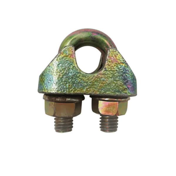
Wire rope clips are widely used for making end terminations. Clips are available in two basic designs; the U-Bolt and fist grip. The efficiency of both types is the same.
When using U-Bolt clips, extreme care must be exercised to make certain that they are attached correctly; Incorrect installation can reduce the working load limit by 40%. Below are general guidelines for installing wire rope clips.
The saddle shall be placed on the live end of the wire rope, with the U-bolt on the dead-end side—Remember the well-known saying: “Never saddle a dead horse.” Use at least two or three wire rope clips to secure the ends properly to the length of the rope, and tighten nuts evenly one by one until reaching the recommended torque.
Step 1. Turn back a specified amount of rope from the thimble or loop. The first clip must be placed one bridge width from the turned back rope tailor dead end of the rope, Apply U-Bolt over dead end of wire rope – live end rests in the saddle (Never saddle a dead horse!) Tighten nuts evenly, alternate from one nut to the other until reaching the recommended torque.
Step 2. When more than two clips are required, apply the second clip as near the loop or thimble as possible, tighten the nuts firmly but not yet to the specified torque.
Step 3. When three or more clips are required, space additional clips equally between the first two – take up rope slack – tighten nuts on each U-Bolt evenly, alternating from one nut to the other until reaching recommended torque.
In accordance with good rigging and maintenance practices, the wire rope end termination should be inspected periodically for wear, abuse, and general adequacy. Periodically re-tightening of the nuts must be done at 10.000 cycles (heavy usage), 20.000 e.g. every 3 months, 6 months, annually.
Malleable clips are to be used for making eye termination assemblies only with the right regular lay wire rope and only for light-duty uses with small applied loads, such as handrails, fencing, guard rails, etc.
If you have any wire rope clips questions, you can contact us by email at info@hilifting.com. We will be glad to share with you more useful information.
Original equipment wire rope and replacement wire rope must be selected and installed in accordance with the requirements of this section. Selection of replacement wire rope must be in accordance with the recommendations of the wire rope manufacturer, the equipment manufacturer, or a qualified person.
Wire rope design criteria: Wire rope (other than rotation resistant rope) must comply with either Option (1) or Option (2) of this section, as follows:
Option (1). Wire rope must comply with section 5-1.7.1 of ASME B30.5-2004 (incorporated by reference, see § 1926.6) except that section"s paragraph (c) must not apply.
Option (2). Wire rope must be designed to have, in relation to the equipment"s rated capacity, a sufficient minimum breaking force and design factor so that compliance with the applicable inspection provisions in § 1926.1413 will be an effective means of preventing sudden rope failure.
Type I rotation resistant wire rope ("Type I"). Type I rotation resistant rope is stranded rope constructed to have little or no tendency to rotate or, if guided, transmits little or no torque. It has at least 15 outer strands and comprises an assembly of at least three layers of strands laid helically over a center in two operations. The direction of lay of the outer strands is opposite to that of the underlying layer.
Type II rotation resistant wire rope ("Type II"). Type II rotation resistant rope is stranded rope constructed to have significant resistance to rotation. It has at least 10 outer strands and comprises an assembly of two or more layers of strands laid helically over a center in two or three operations. The direction of lay of the outer strands is opposite to that of the underlying layer.
Type III rotation resistant wire rope ("Type III"). Type III rotation resistant rope is stranded rope constructed to have limited resistance to rotation. It has no more than nine outer strands, and comprises an assembly of two layers of strands laid helically over a center in two operations. The direction of lay of the outer strands is opposite to that of the underlying layer.
Type I must have an operating design factor of no less than 5, except where the wire rope manufacturer and the equipment manufacturer approves the design factor, in writing.
A qualified person must inspect the rope in accordance with § 1926.1413(a). The rope must be used only if the qualified person determines that there are no deficiencies constituting a hazard. In making this determination, more than one broken wire in any one rope lay must be considered a hazard.
Each lift made under § 1926.1414(e)(3) must be recorded in the monthly and annual inspection documents. Such prior uses must be considered by the qualified person in determining whether to use the rope again.
Rotation resistant ropes may be used as boom hoist reeving when load hoists are used as boom hoists for attachments such as luffing attachments or boom and mast attachment systems. Under these conditions, all of the following requirements must be met:
The requirements in ASME B30.5-2004 sections 5-1.3.2(a), (a)(2) through (a)(4), (b) and (d) (incorporated by reference, see § 1926.6) except that the minimum pitch diameter for sheaves used in multiple rope reeving is 18 times the nominal diameter of the rope used (instead of the value of 16 specified in section 5-1.3.2(d)).
The operating design factor for these ropes must be the total minimum breaking force of all parts of rope in the system divided by the load imposed on the rope system when supporting the static weights of the structure and the load within the equipment"s rated capacity.
Wire rope clips used in conjunction with wedge sockets must be attached to the unloaded dead end of the rope only, except that the use of devices specifically designed for dead-ending rope in a wedge socket is permitted.
Prior to cutting a wire rope, seizings must be placed on each side of the point to be cut. The length and number of seizings must be in accordance with the wire rope manufacturer"s instructions.

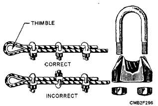
U-bolt Clips.There is only one correct method for attaching U-bolt clips to wire rope ends, as shown in TheRightWayimage below. The base of the clip bears on the live end of the rope; the “U” of the bolt bears on the dead end.
Compare this with the incorrect methods. Five of the six clips shown are incorrectly attached—only the center clip in the top view is correct. When the “U” of the clip bears on the live end of the rope, there is a possibility of the rope being cut or kinked, with subsequent failure.
U-bolt on the bitter (dead) end, not on the standing part of the wire rope. If clips are attached incorrectly, the standing part (live end) of the wire rope will be distorted or have mashed spots. A rule of thumb when attaching a wire rope is to NEVER saddle a dead horse.
Another type of wire rope clip is the twin-base clip, often referred to as the universal or two clamp (fig. 6-56). Both parts of this clip are shaped to fit the wire rope, so the clip cannot be attached incorrectly. The twin-base clip allows for a clear 360-degree swing with the wrench when the nuts are being tightened.
THIMBLE. - When an eye is made in a wire rope, a metal fitting, called a thimble, is placed in the eye, as shown in figure 6-55. The thimble protects the eye against wear. Wire rope eyes with thimbles and wire rope clips can hold approximately 80 percent of the wire rope strength.
After the eye made with clips has been strained, the nuts on the clips must be re-tightened. Checks should be made now and then for tightness or the clips will cause damage to the rope.
SWAGED CONNECTIONS. - Swaging makes an efficient and permanent attachment for wire rope, as shown in figure 6-57. A swaged connection is made by compressing a steel sleeve over the rope by using a hydraulic press. When the connection is made properly, it provides 100 percent capacity of the wire rope.
Careful inspection of the wires leading into these connections is important because of the pressure put upon the wires in this section. If one broken wire is found at the swaged connection or a crack in the swage, replace the fitting.
HOOKS AND SHACKLES. - Hooks and shackles are handy for hauling or lifting loads without tying them directly to the object with line, wire rope, or chain. They can be attached to wire rope, fiber line, blocks, or chains. Shackles should be used for loads too heavy for hooks to handle.

(a) Before installing a wire rope clip on plastic coated or plastic impregnated wire rope, the wire rope clip manufacturer, you must consult the wire rope manufacturer or a qualified person.
(b) For U-bolt clips used to create end terminations, you must place the saddle on the live end of the wire rope, with the U-bolt on the dead end side. (See Figure 24, Wire Rope Clips.)
(c) You must test the assembly by loading the connection to at least the expected working load. After unloading, retighten the wire rope clips to the torque recommended by the manufacturer or a qualified person.
(d) You must follow the manufacturer"s recommendations for the minimum number of clips, spacing and turn-back measurements, and to the recommended torque values. In the absence of the manufacturer"s recommendations follow Table 5.
(b) Before installing a wedge socket on plastic coated or plastic impregnated wire rope the wedge socket manufacturer, you must consult the wire rope manufacturer or a qualified person.
(c) The assembler must match the proper wedge with the socket for the wire rope to be installed. Wedges must not be interchanged between different manufacturers" sockets or models.
(f) The tail of the dead end of the wire rope extending beyond the wedge socket must be secured as recommended by the wedge socket manufacturer or a qualified person.
(g) The dead end of the wire rope must not be secured to the live end of the wire rope in a way that restricts the movement of the live end. (See Figure 25.)

A kind of card rope formula fastener 3 of the first embodiment as shown in Figure 3,4, it comprises: male fastener 31 and mother buckle 32, above-mentioned male fastener 31 is for being arranged at pin thread on clothing 4 as shown in Figure 3.
As Fig. 4, shown in 5, above-mentioned mother buckle 32 has wire rope handling portion 323, above-mentioned wire rope handling portion 323 has the first perforate 323a and the second perforate 323b, wherein, above-mentioned the first perforate 323a is arranged on the first side 321 of above-mentioned mother buckle 32, above-mentioned the first perforate 323a is connected to internal surface by above-mentioned the first side 321 outer surfaces, above-mentioned the second perforate 323b is arranged on the second side 322 of above-mentioned mother buckle 32, with the first perforate 323a in the same manner, above-mentioned the second perforate 323b is connected to internal surface by above-mentioned the second side 322 outer surfaces, and above-mentioned two perforates form the passage 323c wearing for rope body 41, in this embodiment, above-mentioned passage 323c and fit portion 324 interconnect runs through.
As shown in Figure 4,5, the surface, outside of above-mentioned mother buckle 32 is provided with to engage the joining portion 325 of above-mentioned rope body 41, the groove 325a of above-mentioned joining portion 325 for caving inward from surface, on take off groove 325a and can hold rope body 41 in wherein, the body 41 that makes to restrict is along groove 325a around fastener body.
The use view of blocking as shown in Figure 6 rope formula fastener 3, by rope body 41, wear by above-mentioned the first perforate 323a and the second perforate 323b, again by male fastener 31 in order to be sleeved on the fit portion 324 of mother buckle 32, fit portion 324 by mother buckle 32 coordinates the male fastener 31 being positioned on clothing 4 to be fastened, male fastener 31 on clothing 4 can be supported be fixed on fit space 324c inner, and support and fix male fastener 31 by above-mentioned first set component 324d (please refer to the drawing 5) and the second engagement piece 324e (please refer to the drawing 5), it is rear further in joining portion 325 that last above-mentioned rope body 41 wore wire rope handling portion 323, the body 41 that makes to restrict is 325 fixing along joining portion, wherein, as shown in the figure, wear by rope body 41 axle center of above-mentioned wire rope handling portion 323 with rope body 41 axle center around above-mentioned joining portion 325 as mutually vertical.
In an embodiment as shown in Figure 7, above-mentioned joining portion 325 is two fin 325b that stretched out and protruded by surface, on take off that rope body 41 (not shown) can be contained in the space in the middle of two fin 325b and spacing, body 41 (not shown) that make to restrict are around living fastener body.
In sum, feature of the present utility model be the mother buckle of integral type is had can the fit portion of engaging on male fastener, and utilize the set joining portion structure in mother buckle outside, the rope body being arranged in the utility model wire rope handling portion is fixed on special position, reduce the chance that rope body leaves fastener body, on take off structure and can avoid fastener and rope body in when motion, between advancing because of concussion produce free displacement cause pull impaired, therefore can extend product working life, and replace the known structure that coordinates two separated type members of controlling member with wire rope handling portion with single type structure, and then reach and reduce commodity number of elements, reduce costs, increase the effect of industry applications.


 8613371530291