
wire rope clips osha quotation

This responds to your June 1, 1999, letter to the Occupational Safety and Health Administration (OSHA), requesting information on wire rope and Crosby clips used around the perimeter of buildings as a guardrail. You also requested clarification on when employees must tie-off when a guardrail system is removed to facilitate hoisting operations. We apologize for the long delay in providing this response.
Question 1: How many Crosby clips are required to be used when setting up a wire rope guardrail? Is it permissible to splice two wire ropes by overlapping or must the connections be turned back into eyelets and properly secured?
Answer: For construction work covered by 29 CFR 1926 Subpart M, §1926.502(b) sets forth the criteria that must be met when using wire rope as a guardrail. The standard requires guardrails to meet several specific criteria. For example, 1926.502(b)(3) states that the guardrail shall be capable of withstanding, without failure, a force of at least 200 pounds applied within 2 inches of the top edge, in any outward or downward direction, at any point along the top edge. Section 1926.502(b)(4) states that when the 200 pound test load noted in §1926.502(b)(3) is applied in a downward direction, the top edge of the guardrail shall not deflect to a height less than 39 inches above the walking/working level. Section 1926.502(b)(9) states that the top rail and mid-rails shall be at least ¼-inch nominal diameter or thickness to prevent cuts and lacerations. These and other criteria must be met when using wire rope as a guardrail around the perimeter of a building.
The OSHA standard does not specify a minimum number of clips when using wire rope as a guardrail. However, as a practical matter, it is unlikely you could meet the specific requirements under §1926.502(b) unless you follow the manufacturer"s recommendations for the number of clips to be used on wire ropes of different diameters (for example, the Crosby Group Inc. general catalog, 2000 edition has tables showing their recommendations for their clips). Also, note that OSHA"s standard for rigging equipment used for material handling, 29 CFR §1926.251, has a table for the number of clips required for wire rope ½-inch and greater. Although that standard does not apply to wire rope used for guardrails, when you design a rope system to meet the §1926.502 requirements, following those tables will normally ensure that you have enough clips.
If you need additional information, please contact us by fax at: U.S. Department of Labor, OSHA, Directorate of Construction, Office of Construction Standards and Guidance, fax # 202-693-1689. You can also contact us by mail at the above office, Room N3468, 200 Constitution Avenue, N.W., Washington, D.C. 20210, although there will be a delay in our receiving correspondence by mail.

The only comments we have to offer is 29 CFR 1926.251(c)(3), Rigging Equipment for Material Handling, Wire Rope, states that: "Wire rope shall not be secured by knots, except on haul back lines on scrapers." In addition, if this wire rope were used as a bull wire, then 29 CFR 1926.251(c)(4)(iii) requires that eyes in bull wires shall not be formed by knots or wire rope clips. The above standards recognize the hazard of tying knots in wire ropes used for hoisting, lowering, or pulling loads.
An eye splice made in any wire rope shall have at least three tucks with a whole strand of rope and two tucks with one-half of the wires cut out of each strand. However, this requirement shall not operate to preclude the use of another form of splice or connection which can be shown to be as efficient and which is not prohibited by part 1918 of this chapter.
Except for eye splices in the ends of wires, each wire rope used in hoisting or lowering, in guying derricks, or as a topping lift, preventer or pendant shall consist of one continuous piece without knot or splice.
The ends of falls shall be secured to the winch drums by clamps, U-bolts, shackles or some other equally strong method. Fiber rope fastenings shall not be used.
Wire rope shall not be used for the vessel"s cargo gear if in any length of eight diameters, the total number of visible broken wires exceeds 10 percent of the total number of wires, or if the rope shows other signs of excessive wear, corrosion, or defect. Particular attention shall be given to the condition of those sections of wire rope adjacent to any terminal connections, those sections exposed to abnormal wear, and those sections not normally exposed for examination.
Original equipment wire rope and replacement wire rope must be selected and installed in accordance with the requirements of this section. Selection of replacement wire rope must be in accordance with the recommendations of the wire rope manufacturer, the equipment manufacturer, or a qualified person.
Wire rope design criteria: Wire rope (other than rotation resistant rope) must comply with either Option (1) or Option (2) of this section, as follows:
Option (1). Wire rope must comply with section 5-1.7.1 of ASME B30.5-2004 (incorporated by reference, see § 1926.6) except that section"s paragraph (c) must not apply.
Option (2). Wire rope must be designed to have, in relation to the equipment"s rated capacity, a sufficient minimum breaking force and design factor so that compliance with the applicable inspection provisions in § 1926.1413 will be an effective means of preventing sudden rope failure.
Type I rotation resistant wire rope ("Type I"). Type I rotation resistant rope is stranded rope constructed to have little or no tendency to rotate or, if guided, transmits little or no torque. It has at least 15 outer strands and comprises an assembly of at least three layers of strands laid helically over a center in two operations. The direction of lay of the outer strands is opposite to that of the underlying layer.
Type II rotation resistant wire rope ("Type II"). Type II rotation resistant rope is stranded rope constructed to have significant resistance to rotation. It has at least 10 outer strands and comprises an assembly of two or more layers of strands laid helically over a center in two or three operations. The direction of lay of the outer strands is opposite to that of the underlying layer.
Type III rotation resistant wire rope ("Type III"). Type III rotation resistant rope is stranded rope constructed to have limited resistance to rotation. It has no more than nine outer strands, and comprises an assembly of two layers of strands laid helically over a center in two operations. The direction of lay of the outer strands is opposite to that of the underlying layer.
Type I must have an operating design factor of no less than 5, except where the wire rope manufacturer and the equipment manufacturer approves the design factor, in writing.
A qualified person must inspect the rope in accordance with § 1926.1413(a). The rope must be used only if the qualified person determines that there are no deficiencies constituting a hazard. In making this determination, more than one broken wire in any one rope lay must be considered a hazard.
Each lift made under § 1926.1414(e)(3) must be recorded in the monthly and annual inspection documents. Such prior uses must be considered by the qualified person in determining whether to use the rope again.
Rotation resistant ropes may be used as boom hoist reeving when load hoists are used as boom hoists for attachments such as luffing attachments or boom and mast attachment systems. Under these conditions, all of the following requirements must be met:
The requirements in ASME B30.5-2004 sections 5-1.3.2(a), (a)(2) through (a)(4), (b) and (d) (incorporated by reference, see § 1926.6) except that the minimum pitch diameter for sheaves used in multiple rope reeving is 18 times the nominal diameter of the rope used (instead of the value of 16 specified in section 5-1.3.2(d)).
The operating design factor for these ropes must be the total minimum breaking force of all parts of rope in the system divided by the load imposed on the rope system when supporting the static weights of the structure and the load within the equipment"s rated capacity.
Wire rope clips used in conjunction with wedge sockets must be attached to the unloaded dead end of the rope only, except that the use of devices specifically designed for dead-ending rope in a wedge socket is permitted.
Prior to cutting a wire rope, seizings must be placed on each side of the point to be cut. The length and number of seizings must be in accordance with the wire rope manufacturer"s instructions.

Efficiency ratings for wire rope end terminations are based upon the minimum breaking force of wire rope. The efficiency rating of a properly prepared loop or thimble-eye termination for clip sizes 1/8” through 7/8” is 80%, and for sizes 1” through 3-1/2” is 90%.
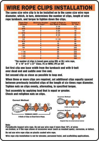
The number of clips shown (see Table 1) is based upon using RRL or RLL wire rope, 6 x 19 or 6 x 36 Class, FC or IWRC; IPS or XIP, XXIP. If Seale construction or similar large outer wire type construction in the 6 x 19 Class is to be used for sizes 1 inch and larger, add one additional clip. If a pulley (sheave) is used for turning back the wire rope, add one additional clip.
The number of clips shown also applies to rotation-resistant RRL wire rope, 8 x 19 Class, IPS, XIP, XXIP sizes 1-1/2 inch and smaller; and to rotation-resistant RRL wire rope, 19 x 7 Class, IPS, XIP, XXIP sizes 1-3/4 inch and smaller.
For elevator, personnel hoist, and scaffold applications, refer to ANSI A17.1 and ANSI A10.4. These standards do not recommend U-Bolt style wire rope clip terminations. The style wire rope termination used for any application is the obligation of the user.
Turn back specified amount of rope from thimble or loop. Apply first clip one base width from dead end of rope. Apply U-Bolt over dead end of wire rope – live end rests in saddle (Never saddle a dead horse!). Use torque wrench to tighten nuts evenly, alternate from one nut to the other until reaching the recommended torque. (See Figure 1 below)
Use torque wrench to tighten nuts evenly, alternating until reaching the recommended torque. When more than two clips are required, apply the second clip as near the loop or thimble as possible, turn nuts on second clip firmly, but do not tighten. (See Figure 2 below)
Space additional clips equally between first two – take up rope slack – use torque wrench to tighten nuts on each U-Bolt evenly, alternating from one nut to the other until reaching recommended torque. (See Figure 3 below)
The preferred method of splicing two wire ropes together is to use inter-locking turnback eyes with thimbles using the recommended number of clips on each eye (See Figure 5 below).
An alternate method is to use twice the number of clips as used for a turnback termination. The rope ends are placed parallel to each other, overlapping by twice the turnback amount shown in the application instructions. The minimum number of clips should be installed on each dead end (See Figure 6 below). Spacing, installation torque, and other instructions still apply.
Apply first load to test the assembly. This load should be of equal or greater weight than loads expected in use. Next, check and use torque wrench to retighten nuts to recommended torque. In accordance with good rigging and maintenance practices, the wire rope end termination should be inspected periodically for wear, abuse, and general adequacy.
SLING IDENTIFICATION Employers must use only wire-rope slings that have permanently affixed and legible identification markings as prescribed by the manufacturer, and that indicate the recommended safe working load for the type(s) of hitch(es) used, the angle upon which it is based, and the number of legs if more than one.
MINIMUM SLING LENGTHSCable laid and 6×19 and 6×37 slings shall have a minimum clear length of wire rope 10 times the component rope diameter between splices, sleeves or end fittings.
SAFE OPERATING TEMPERATURESFiber core wire rope slings of all grades shall be permanently removed from service if they are exposed to temperatures in excess of 200°F. When nonfiber core wire rope slings of any grade are used at temperatures above 400°F or below minus 60°F, recommendations of the sling manufacturer regarding use at that temperature shall be followed.
REMOVAL FROM SERVICEWire rope slings shall be immediately removed from service if any of the following conditions are present:Ten randomly distributed broken wires in one rope lay, or five broken wires in one strand in one rope lay.
SLING IDENTIFICATIONEmployers must use natural and synthetic fiber-rope slings that have permanently affixed and legible identification markings stating the rated capacity for the type(s) of hitch(es) used and the angle upon which it is based, type of fiber material, and the number of legs if more than one.
SAFE OPERATING TEMPERATURESNatural and synthetic fiber rope slings, except for wet frozen slings, may be used in a temperature range from minus 20°F to plus 180°F without decreasing the working load limit. For operations outside this temperature range and for wet frozen slings, the sling manufacturer’s recommendations shall be followed.
SPLICINGSpliced fiber rope slings shall not be used unless they have been spliced in accordance with the following minimum requirements and in accordance with any additional recommendations of the manufacturer:
In manila rope, eye splices shall consist of at least three full tucks, and short splices shall consist of at least six full tucks, three on each side of the splice center line.
In synthetic fiber rope, eye splices shall consist of at least four full tucks, and short splices shall consist of at least eight full tucks, four on each side of the center line.
Strand end tails shall not be trimmed flush with the surface of the rope immediately adjacent to the full tucks. This applies to all types of fiber rope and both eye and short splices. For fiber rope under one inch in diameter, the tail shall project at least six rope diameters beyond the last full tuck. For fiber rope one inch in diameter and larger, the tail shall project at least six inches beyond the last full tuck. Where a projecting tail interferes with the use of the sling, the tail shall be tapered and spliced into the body of the rope using at least two additional tucks (which will require a tail length of approximately six rope diameters beyond the last full tuck).
REMOVAL FROM SERVICENatural and synthetic fiber rope slings shall be immediately removed from service if any of the following conditions are present:Abnormal wear.

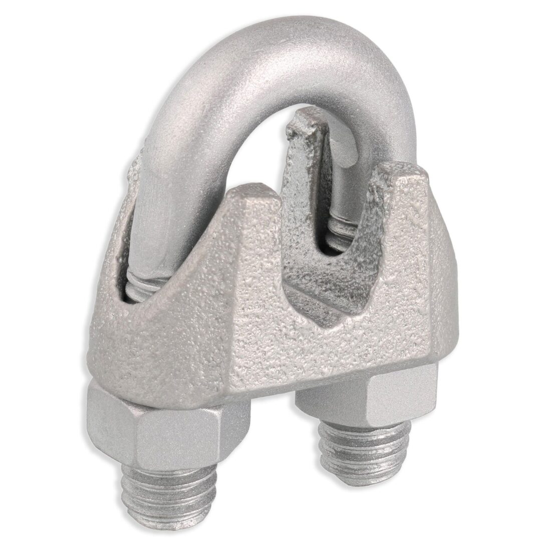
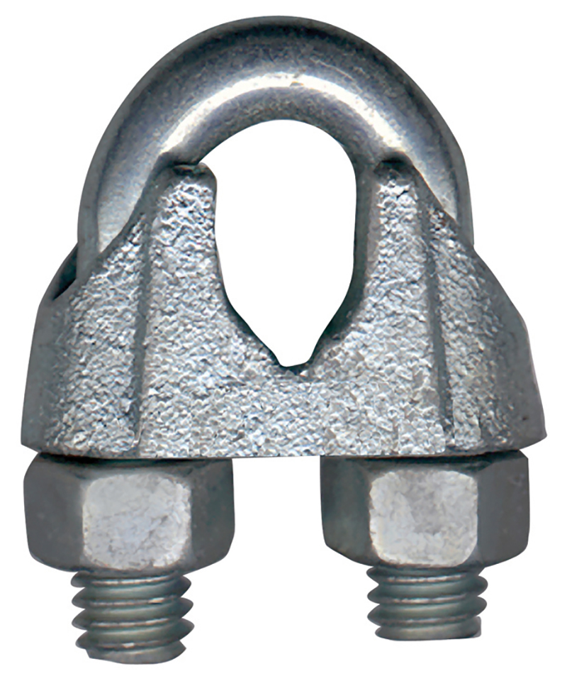
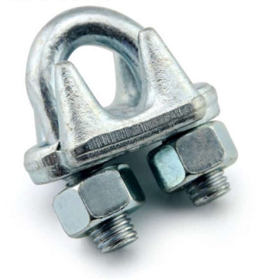
Wire Rope Clips can have lots of helpful uses – they are a simple fitting that can be easily used in the field or shop. Sometimes called a u-bolt or u-bolt clip, they can be used to join two wire rope ends together, make an eye for a pulling application, or to secure the loose end of a wire rope after a wedge socket (or other appropriate device) has been used to terminate a crane’s hook.
But using clips to create wire rope slings for overhead lifting is NOT one of their many uses. Did you know that not only is it a poor rigging practice to fabricate slings in this manner, in the U.S. it is against the law?
ASME B30.9 states that wire rope clips shall not be used to fabricate wire rope slings, except where the application of slings prevents the use of prefabricated slings.
ASME B30.9 states wire rope clips shall be drop-forged steel of single saddle (u-bolt) or double saddle clip. Malleable cast iron clips shall not be used.
Why these restrictions? Wire rope clips diminish the working load limit of the wire rope to generally about 70-75% of its original strength.There are better and more efficient ways to fabricate slings for overhead lifting.
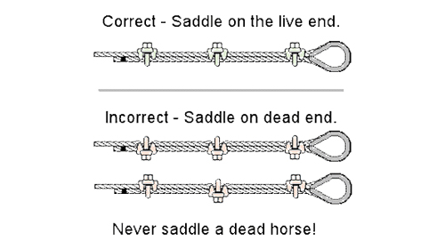
For situations where use of wire rope clips are approved, it’s important to remember the proper way to install the clips. Incorrect installation can reduce the working load limit by 40% or more. The easiest thing is to remember, “never saddle a dead horse.”
The saddle of the clip is the piece that the U bolt fits into. The dead end of a wire rope is the end of the eye that contains the cut side. The U bolt should always be in contact with the dead end, while the saddle should be on the live end.
In addition, for clips to work properly and gain their design efficiency, the proper number of clips is required and the nuts must be torqued as prescribed by the manufacturer. For more information on proper installation, check out this video from the Crosby Group.
If you have more questions on wire rope clips, comment below. Remember that Safety through Education is more than just our motto, it is our guiding principle. If you need training on proper application on any other rigging hardware, reach out to us. We are here for you.

Mechanical Splice and Hand Splice, all slings are made from 6 x 19 EIP wire rope and tested to required load limits. As per OSHA requirements, each wire rope sling has a tag woven into the wire showing the required date and location of manufacture, the dimensions and load limits.
Employers must use only wire-rope slings that have permanently affixed and legible identification markings as prescribed by the manufacturer and that indicate the recommended safe working load for the type(s) of hitch(es) used, the angle upon which it is based, and the number of legs if more than one.”
Contact IBT to schedule a Sling Safety Seminar. The Sling Safety Seminar will be tailored to your facility’s needs. Let IBT and Lift-All train your employees to be compliant with the new OSHA regulation for wire rope slings.
(a) Scope. This section applies to slings used in conjunction with other material handling equipment for the movement of material by hoisting, in employments covered by this Part. The types of slings covered are those made from allow steel chain, wire rope, metal mesh, natural or synthetic fiber rope (conventional three strand construction), and synthetic web (nylon, polyester, and polypropylene).
“Cable laid endless sling-mechanical joint” is a wire rope sling made endless by joining the ends of a single length of cable laid rope with one or more metallic fittings.
“Cable laid grommet-hand tucked” is an endless wire rope sling made from one length of rope wrapped six times around a core formed by hand tucking the ends of the rope inside the six wraps.
“Cable laid rope sling-mechanical joint” is a wire rope sling made from a cable laid rope with eyes fabricated by pressing or swaging one or more metal sleeves over the rope junction.
“Master link” or “gathering ring” is a forged or welded steel link used to support all members (legs) or an alloy steel chain sling or wire rope sling. (See Fig. N-184-3.)
“Strand laid endless sling-mechanical joint” is a wire rope sling made endless from one length of rope with the ends joined by one or more metallic fittings.
“Strand laid grommet-hand tucked” is an endless wire rope sling made from one length of strand wrapped six times around a core formed by hand tucking the ends of the strand inside the six wraps.
“Strand laid rope” is a wire rope made with strands (usually six or eight) wrapped around a fiber core, wire strand core, or independent wire rope core (IWRC).


 8613371530291