
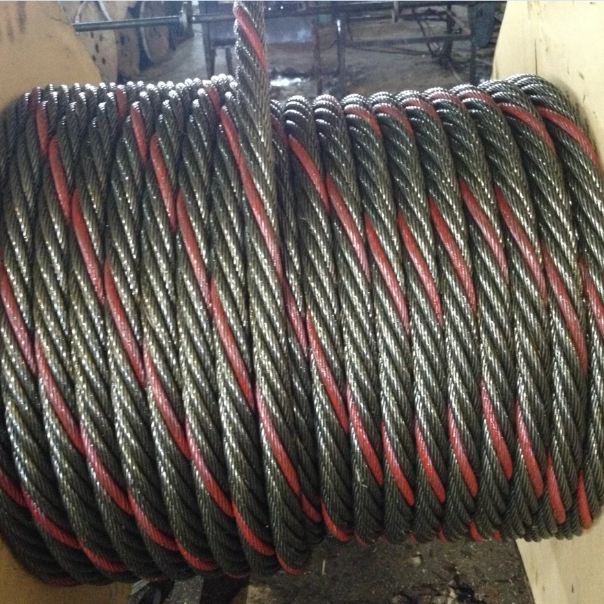
wire rope coiler free sample
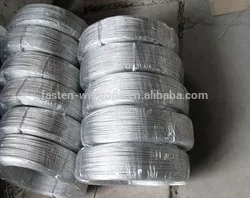
Nantong Fasten Metals Products Co., LTD is located in the coastal open city—Nantong which is in the lower area of the Yangtze River. We are a professional corporation which produces a variety of standards and types of galvanized steel wire rope, ungalvanized steel wire rope, steel-wire, stranded wire and spring steel wire. Our products mainly exported to Southeast Asia, the United States, Europe, the Middle East, Africa and other countries.
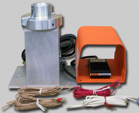
LTL Tooling custom manufactures Wire Coilers for the wire industry. This wire coiler is a device that can coil wire, terminated wire, rope, line and cable. It is electronically foot pedal operated and turns when the foot pedal is depressed. We offer different diameter spools to meet our customers needs.
Barbed wire fencing strong sharply pointed element twisted around art pattern industrial barbwire protection concept design modern metallic sharp element for area protection
Barbed wire fencing strong sharply pointed element twisted around art pattern industrial barbwire protection concept design modern metallic sharp element for area protection
Wire rope is shipped in cut lengths, either in coils or on reels. Great care should be taken when the rope is removed from the shipping package since it can be permanently damaged by improper unreeling or uncoiling. Looping the rope over the head of the reel or pulling the rope off a coil while it is lying on the ground, will create loops in the line. Pulling on a loop will, at the very least, produce an imbalance in the rope and may result in open or closed kinks (Fig. 18). Once a rope is kinked, the damage is not repairable. The kink must be cut out or the rope is unfit for service.
Figure 18.Improper handling can create open (a) or, closed kinks b). The open kink will open the rope lay: the closed kink will close it. Starting loop (c): Do not allow the rope to form a loop. If. however, a loop does form and is removed at the stage show. a kink can be avoided. Kink (d): In this case. the looped rope was put under tension, the kink was formed. the rope is permanently damaged.
There are three methods to perform this step correctly:The reel is mounted on a shaft supported by two jacks or a roller payoff (Fig.19). Since the reel is free to rotate, the rope is pulled from the reel by a workman holding the rope end, and walking away from the reel as it unwinds. A braking device should be employed so that the rope is kept taut and the reel is restrained from over-running the rope. This is necessary particularly with powered de-reeling equipment.
Another method involves mounting the reel on an unreeling stand (Fig. 20). It is then unwound in the same manner as described above (1). In this case, however, greater care must be exercised to keep the rope under tension sufficient to prevent the accumulation of slack. Slack can allow the rope to drop below the lower reel head and be damaged or loose wraps on the reel to fall
In another accepted method, the end of the rope is held while the reel itself is rolled along the ground. With this procedure, the rope will payoff properly however, the end being held will travel in the direction the reel is being rolled. As the difference between the diameter of the reel head and the diameter of the wound rope increases, the speed of travel will increase.
Figure 19. The wire rope reel is mounted on a shaft supported by jacks. This permits the reel to rotate freely. and the rope can be unwound either manually or by a powered mechanism.
When re-reeling wire rope from a horizontally supported reel to a drum it is preferable for the rope to travel from the top of the reel to the top of the drum; or, from the bottom of the reel to the bottom of the drum (Fig. 21). Re-reeling in this manner will avoid putting a reverse bend into the rope during installation. If a rope is installed so that a reverse bend is induced, it may cause the rope to become "twisty" and, consequently, harder to handle. When unwinding wire rope from a coil, there are two suggested methods for carrying out this procedure in a proper manner:
1) One method involves placing the coil on a vertical unreeling stand. The stand consists of a base with a fixed vertical shaft. On this shaft there is a "swift," consisting of a plate with inclined pins positioned so that the coil may be placed over them. The whole swift and coil then rotate as the rope is pulled off. This method is particularly effective when the rope is to be wound on a drum.
2) The most common as well as the easiest uncoiling method is merely to hold one end of the rope while rolling the coil along the ground like a hoop (Fig. 22). Figures 23 and 24 show unreeling and uncoiling methods that are most likely to cause kinks. Such improper procedures must be avoided in order to prevent the occurrence of loops. These loops, when pulled taut, will inevitably result in kinks. No matter how a kink develops, it will damage strands and wires, and the kinked section must be cut out. Proper and careful handling will keep the wire rope free from kinks.
Drums are the means y which power is transmitted to the rope and then to the object to be moved. For the wire rope to pick up this power efficiently and to transmit it properly to the working end, the installation must be carefully controlled. If the drum is grooved, the winding conditions should be closely supervised to assure adherence to the following recommended procedures:
I) The end of the rope must be secured to the drum by such means as will give the end termination at least as much strength as is specified by the equipment manufacturer.
2) Adequate tension must be maintained on the rope while it is being wound so that the winding proceeds under continuous tension. Back tension applied to the rope during installation" should be from 2 to 5% of the minimum breaking force of the rope being installed.
4) It is preferable to have at least three dead wraps remaining on the drum when the rope is unwound during normal operation. Two dead wraps are a mandatory requirement in many codes and standards. If the wire rope is carelessly wound and, as a result, jumps the grooves, it will be crushed and cut where it crosses from one groove to the other. Another, almost unavoidable problem is created at the drum flange; as the rope climbs to a second layer there is further crushing and the wires receive excessive abrasion.
drum grooves relative to the actual rope diameter. Wire rope is normally manufactured to a plus tolerance. (See Table 3.) The oversize tolerance of the rope must be taken into account or the rope will be damaged by poor spooling caused
inches. Yet, by Federal standards, a 1/4-inch rope may have a diameter as large as .265 inches. If a rope of this size were to be operated on a drum with a .250 inch pitch, crowding would occur and the rope would be forced out of the groove.
Installation of a wire rope on a plain (smooth) face drum requires a great deal of care. The starting position should be at the correct drum flange so that each wrap of the rope will wind tightly against the preceding wrap (Fig. 32). Here too, close supervision should be maintained during installation. This will help make certain that:
2 ) Appropriate tension on the rope is maintained as it is wound on the drum. Back tension applied to the rope during installation should be from 2 to 5% of the minimum breaking force of the rope being installed.
4) It is preferable to have at least three dead wraps remaining on the drum when the rope is unwound during normal operation. Two dead wraps are a mandatory requirement in many codes and standards. Loose and uneven winding on a plain (smooth) faced drum can and usually does create excessive wear, crushing and distortion of the rope. The results of such abuse are shorter service life and a reduction in the rope"s effective strength. Also, for an operation that is sensitive in terms of moving and spotting a load, the operator will encounter control difficulties as the rope will pile up, pull into the pile and fall from the pile to the drum surface. The ensuing shock can break or otherwise damage the rope.
Figure 32. By holding the right or left hand with index finger extended, palm up or palm down, the proper procedure for applying left-and right-lay rope on a smooth drum can be easily determined.
The proper direction of winding the first layer on a smooth drum can be determined by standing behind the drum and looking along the path the rope travels, and then following one of the procedures illustrated in Figure 32. The diagrams show: the correct relationship that should be maintained between the direction of lay of the rope (right or left), the direction of rotation of the drum (overwind or underwind) and winding from left to right or right to left. Order Wire Rope & Cable
Many installations are designed with requirements for winding more than one layer of wire rope on a drum. Winding multiple layers presents some further problems.The first layer should wind in a smooth, tight helix which, if the drum is grooved,
is already established. The grooves allow the operator to work off the face of the drum, and permit the minimum number of dead wraps. A smooth drum present" an additional problem, initially, as the wire rope must be wound in such a manner that the first layer will be smooth and uniform and will provide a firm foundation for the layers of rope that will be wound over it. The first layer of rope on the smooth drum should be wound with tension (2 to 5% of the minimum breaking force of the rope) sufficient to assure a close helix - each wrap being wound as close as possible to the preceding wrap. The first layer then acts as a groove which will guide the successive layers. Unlike wire ropes operating on grooved drums, the first layer should not be unwound from a smooth-faced drum with multiple layers. After the rope has wound completely across the face of the drum (either smooth or grooved), it is forced up to a second layer at the flange. The rope then winds back across the drum in the opposite direction, lying in the valleys between the wraps of the rope on the first layer. Advancing across the drum on the second layer, the rope, following the "grooves" formed by the rope on the first layer, actually winds back one wrap in each revolution of the drum. The rope must then cross one or two rope "grooves" (depending upon the type of grooving - single or double cross-over) in order to advance across the drum for each turn. The point at which this occurs is known as the cross-over. Cross-over is unavoidable on the second, and all succeeding layers. Figure 33 illustrates the winding of a rope on the second layer from left to right, and from right to left-the direction is shown by the arrows.
At these cross-over points, the rope is subjected to severe abrasion and crushing as it is pushed over the "grooves" and rides across the crown of the first rope layer. The scrubbing of the rope, as this is happening, can easily be heard.
Helical grooving does not employ a built in cross-over and does not work as well for multiple layers spooling as a counterbalanced drum because it does not have the cross-over and does not consistently put the rope in the proper position at the
Counterbalance grooving with two cross-overs is made so that each wrap of rope winds parallel to the drum flange for a distance less than half the circumference around the drum, then follows a short cross-over to complete half the drum circumference. The cross-over is at an angle with the drum flange and displaces the rope laterally by half the pitch of grooving.
The grooving for this type of winding is similar to the parallel grooving except that half the drum circumference is laterally displaced from the other half by half the pitch of grooving, and between these two halves the grooves make short cross-overs to guide the rope properly. The two cross-over areas are on opposite sides of the drum, or 1800 apart.
Since the lateral displacement of each cross-over is one half the pitch of grooving, or one half the displacement of the cross-overs encountered with other types of winding, "throw" of the rope is reduced, decreasing the whipping action. However, if the interval between these displacements happens to match the rope"s vibration cycle, whipping can still become severe because this action is cumulative.
With counterbalance winding, the change of layers can be controlled better than with other systems and is preferred when a rope must wind in many layers on the drum.

EN12385-2 Steel wire ropes – Safety – Definitions, designation and classification provides a detailed explanation of all the terms and abbreviations used when describing a wire rope and its components. Below are a few of the most common abbreviations;
Steel wire ropes are specified in terms of a Nominal Rope Diameter and when produced have a manufacturing diameter tolerance, this tolerance can vary depending upon customer requirements and specifications and is often dictated by the diameter of grooving within sheaves and drums in which the wire rope will be expected to operate. If no diameter tolerance is specified, the general diameter tolerance is, Nominal Diameter +0% to +5% as specified within various International Rope Standards (EN12385-4, API-9A, ISO 2408). However, please note other diameter tolerances may be applied to ‘small’ diameter ropes and ropes used for specific applications/industries e.g. Mining, Aerials, Elevators, etc.
When designing any rope operated equipment, designers should consider the relevant National and/or International Standards which refer to acceptable sheave and drum diameters based upon the application, industry, etc. The diameter of sheaves and drums together with the tension, are normally associated with overall service life of the rope and in ‘simple terms’ the larger the diameter the longer the service life, although consideration should also be given to the anticipated modes of rope deterioration which will also significantly affect the service life. Typically, the diameter of sheaves and drums for crane applications are 16 to 28 times the nominal rope diameter.
Wire ropes are generally subjected to a visual examination and specifically for crane ropes these is an International Standard ISO 4309 “Cranes – Wire ropes – Care and maintenance, inspection and discard” which provides guidance on the inspection of wire ropes and provide the discard criteria. The document also includes information on the Magnetic testing of roper in service / Non-Destructive Examination and how this can assist the competent person in combination with his visual examination, determine the overall condition of the rope. All wire ropes should be inspected on a routine basis by a competent person to ensure that they remain is a good condition whilst in service and removed from service before they become dangerous. However, this standard is used for offering guidance for ropes operating in other systems where no specific discard criteria are given for that application, industry or country in which the rope is operating.
Please note, wire ropes can cause death and/or serious injury if not correctly handles, operated and maintained to good condition and care should always be taken when work with or close to wire ropes.
A new rope can easily be damaged if the pulley wheel groove is too tight, this will in effect pinch the rope probably causing a wave (spiral) deformity in your new rope.
If left unchecked in a steel pulley, parallel, linear fatigue wire breaks will be found where the contact pressures have become too high, due to a pinch affect.
The Lang’s construction, due to the wires running across the axis of the rope is the same direction as the strand, provides a greater length of wire on the exterior surface of the rope and hence since there is an increased surface area there is an increased area of steel to wear away before a broken wire occurs, therefore offering greater wear resistance. Therefore, applications where the rope is operating over larger number of support rollers and/or sheaves, the Lang’s lay rope may be of benefit.
The direction of the wires within the Lang’s lay construction also reduces the level of mechanical damage and rope interference, which takes place between adjacent wraps of rope within the crossover zones during multi-layer spooling of wire rope.
It is important to state that, single layer strand and parallel laid, rope constructions, manufactured in Lang’s lay, MUST NOT be used with one end free to rotate. Since the wires and the strands as twisted in the same direction, if the rope is free to rotate the wires and the strands will untwist tighter and seriously affect the integrity and breaking strength of the rope.
Wire ropes may be considered as machines, each with approximately 200 to 300 individual wires, which move independently to each over whenever ropes operate around sheaves or spool on or off winch drums, therefore ensuring ropes are lubricated internally will minimise the level of friction between the individual wires and optimise the ropes bend fatigue performance. Lubricant internally and externally will protect the ropes from corrosion and this applies equally to both un-galvanised/bright ropes and galvanised rope. Although the zinc on the surface of the individual wires of a galvanised rope will protect the wires from corrosion, once the zinc has sacrificed itself (oxidised) to protect the steel, the wires are then susceptible to corrosion. The longer the zinc can be protected by the lubricant the longer the zinc remains to offer protection to the steel. However there are applications where internal or external lubricant on the rope may not be advisable, anywhere the lubricant could drop off the rope and contaminate products (paper, food, etc.) in the vicinity of the rope or where the lubricant on the exterior of the rope may be contaminated with debris in the atmosphere (grit, sand, etc.). In this application, it must be accepted that ‘dry’ ropes will have a significantly reduced service life.
Ropes may be lubricated in-service with either oil or grease, both products offering slightly different benefits. Oils may be applied from a portable spray unit and although the ropes may require being re-lubricated more frequently, since it is relatively easy and cleaning to apply, operators are more likely to re-lubricate the ropes in service. The thin oil may penetrate the rope and surface coat the exterior of the rope with a thin film of lubricant, which also allows for relatively easy routine visual inspection of the rope. Alternatively, rope may be lubricated with a soft bearing type grease; the grease may be applied using a suitable pressure greasing system (Masto, Viper, etc.) to ensure uniform coating of grease along the total length of the rope passing through the greasing system, although the level and colour of grease may make visual inspection difficult. It is important that any oil or grease used to lubricate ropes in service is compatible with the lubricant applied to the rope during manufacturing and Bridon-Bekaert offer a range of wire rope lubricants specially formulated to be suitable for most environments and operations, including ECO VGP 2013 compliant (Bio-degradable, Non-toxic & Non-accumulative) products.
For ropes operating above ambient temperature consideration must be given to the effects the operating temperature may have on the wire rope. For guidance, unless otherwise stated, the maximum operating temperatures are provided in the International Standards e.g. EN 12385-3. However searches of these standards by Bridon-Bekaert indicate that the quoted temperatures within the standards have remained constant for a significant period of time, having been developed when rope constructions and usage centred around common 6-stranded rope constructions. With the introduction of more complex rope constructions incorporating higher tensile grade wires, synthetic lubricants and polymers, Bridon-Bekaert’s experiences indicate that reconsideration of the maximum operating temperatures is required. For high performance ropes incorporating synthetic lubricants and polymers Bridon-Bekaert recommend a maximum operating temperature of 100 degrees C. Excessive bleed out of lubricant from the rope may occur depending upon the rope operating temperature and the type/composition of the lubricant and frequent re-lubrication may be required.
Certain applications (Heave compensation systems, etc.) can generate high operating temperatures and for these and any application or where ropes are stored above ambient temperature, Bridon-Bekaert would be please to discuss this subject further.
Also due the smoothness of the circumference of these rope designs, they reduce wear at the cross over contact points as the rope wraps over itself as it is wound onto the drum.
An Ordinary lay rope is where the individual wires in the outer strands are spun / twisted together in the opposite direction to the direction the outer strands are twisted around the core, which results in the individual wires running along the axis of the rope. A Lang’s lay rope is where the individual wires in the outer stands are twisted in the same direction as the outer strands are twisted around the core, which results in the individual wires running across the rope in the same direction as the strands.
It is important to state that a left hand lay rope and a right hand lay rope MUST never be joined together unless the jointing mechanism is prevented from rotating, otherwise the rope will be allowed to un-twist together, which may have a significant effect on the integrity of the ropes, and could result in failure of the rope. There are two particular situations/arrangements where a left hand and/or right hand rope combination may be considered beneficial;
To prevent rotation of load – Twin rope operating systems (Overhead hoists, Grabbing systems, Container handling cranes, etc.) are generally designed to utilise one left hand rope and one right hand lay rope. When lifting a load both ropes will be subjected to an axial load and will try to un-twist, but since the ropes have been spun in different directions during manufacture one rope will trying to un-twist in one direction whilst the other rope will try to un-twist in the opposite direction, the two ropes therefore acting against each other to prevent/minimise rotation of the load.
When spooling a rope – Tension is generally applied to ropes whilst they are being spooled on to a winch drum and this tension will try to rotate / untwist the rope and therefore it is preferable to have the rope rotating up against the previous wrap of rope to minimise ‘gapping’ between the adjacent wrap of rope particularly on the bottom layer. Therefore, to achieve this, depending if the rope is anchored on the left or right hand side of the drum or the rope is being spooled under-wound or over-wound will determine if, a left or right hand lay rope should be utilised.
Rotation Resistant ropes are normally used to lift or suspend a load without the load rotating (example, hoist ropes used on Offshore, Mobile and Tower cranes, etc.) and are constructed by spinning the inner part of the rope in one direction and the outer part of the rope in the opposite direction. When an axial load is then applied to the rope the inner part will try to untwist in one direction and the outer part will try to untwist in the opposite direction, with the two parts of the rope reacting against each other. Rotation Resistant ropes are normally of a multi-strand construction and constructed of 2-layers of strands with the inner layer spun in the opposite direction to the outer layer and of 3-layers of strands with the inner two layers spun in the opposite direction to the outer layer. Three and four stranded rope constructions may also be considered as rotation resistant, but having only three or four strands, the ropes do not exhibit such a smooth exterior profile and may prove to be more difficult to spool, particularly when multi-layer spooled.
Wire rope does not have a defined shelf-live, provided the rope has been stored and maintained to ensure that the rope has not been allowed to deteriorate. To ensure that ropes remain in good condition, it is considered good practice to ensure the ropes are stored off the ground in a well-ventilated environment, protected from the sun, rain, sand/grit/dirt, chemicals or any other forms of contamination. Depending upon the environment the lubricant on the rope will tend to migrate to the bottom of the reel and dry out during storage. It is therefore good practice to rotate reels to prevent the lubricant migrating out of the rope on to the floor and to re-lubricate the ropes during storage by simple spraying a thin oil on to the surface of the rope to prevent the steel wires from corroding and/or zinc coating on the wires from oxidising (white rust). Whilst wire ropes are in storage they should be routinely inspected to ensure they have not been accidentally damaged, that all identification and certification remains in place and that the ropes remain fit for use. Rope being taken from storage on a ‘first in – first out’ basis, to minimise the length of time in storage.


 8613371530291