
wire rope coiling machine free sample

Nantong Fasten Metals Products Co., LTD is located in the coastal open city—Nantong which is in the lower area of the Yangtze River. We are a professional corporation which produces a variety of standards and types of galvanized steel wire rope, ungalvanized steel wire rope, steel-wire, stranded wire and spring steel wire. Our products mainly exported to Southeast Asia, the United States, Europe, the Middle East, Africa and other countries.

If you need a wholesale wire rope coiling machine, Alibaba.com is the platform to visit. This online shop has collaborated with many Alibaba.com dealers to offer customers a wide range of products that lie within their budget. Moreover, the platform offers customization services. So, if you need a custom-made machine, you can place a customization order. This shop also operates on a 24/7 hour clock enabling you to place your order at any time with a few clicks.
Moreover, the cost of the machinery also matters. The cost will largely depend on the model of the equipment. Additionally, the purchasing, installation, and maintenance costs of the machine you select should lie within your budget as it will help you avoid financial strains. Look at the prices offered by different suppliers to land a favorable deal. Lastly, it is important to consider the size of the wire rope coiling machine. The cable manufacturing equipment you buy needs to fit into your working space and leave some space for the operator.
Several industries utilize cable manufacturing equipment. These industries include the medical, telecommunication, military, and automotive industry. Hospitals have specific requirements for their cabling and wiring needs. They require wire rope coiling machine that fulfills those requirements. Secondly, with a wholesale wire ropecoiling machine, the telecommunications industry produces custom-made cables that they use in the manufacture of smartphones, computers, laptops, and tablets. In the military, the equipment is used to produce cables used to power foreign military bases and secure private communications on battlefields. Lastly, the automotive industry uses this machinery to make wires used to suit communication technologies in ambulances and police cruisers. Whether you arere for- industrial purposes or to resell, the chances are you need them fast! with domestic supplies constrained by manufacturing and delivery delays, it makes sense to visit Alibaba.

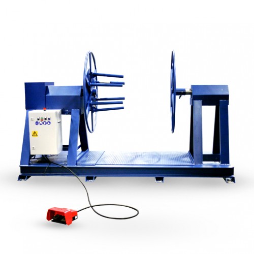
LTL Tooling custom manufactures Wire Coilers for the wire industry. This wire coiler is a device that can coil wire, terminated wire, rope, line and cable. It is electronically foot pedal operated and turns when the foot pedal is depressed. We offer different diameter spools to meet our customers needs.

Manufacturer & distributor of 2D & 3D CNC machinery for bending & forming steel wire or tube from 2 mm to 16 mm size. Machinery is available in various models. Various features include turntables, hydraulic & pneumatic cylinders, turret head indexing tool changers, straighteners, SmartEditor® software, feeders, frame hoppers, limit & proximity switches, controllers & punching, chamfering, threading, drilling, cold heading, cutting, welding, piercing & marking accessories. Industries served include equipment supports construction, automotive, medical, point-of-purchase display, OEM manufacturing, refrigeration, food service, HVAC, storage & material handling.

The invention relates to a device for an apparatus for coiling of cable, wire, wire rope or the like, preferentially an automatic coiling machine, designed for steering and cutting of the cable etc. in conjunction with its reeling on a reeling device for formation of coils.
An often complicated problem in conjunction with automatic coiling machines of this kind is that they must work at high speeds. This means that when a "coil", i.e. a number of adjacent turns of cable, has been formed on a reeling device, the cable must be cut off, the coil removed and the cable-end fixed in the reeling device, without any major interruption in the cable feed occurring. For this purpose the coils are usually wound up on a take-up drum, the hub of which is axially displaceable so that the laid coils can fall out between the flanges of the drum.
The invention has as its object to eliminate these drawbacks and consists of a device for an apparatus for coiling of cable, wire, wire rope or the like, preferentially an automatic coiling machine, designed to steer and cut the cable etc. in conjunction with its reeling on a take-up drum for formation of coils. The especial characteristic of the invention is that the device contains a steering unit or cable feeding and guiding assembly which in addition to lateral reciprocatory movement thereof in a direction parallel to the axis of the takeup drum is also rotatable in a plane substantially perpendicularly to the axis of the take-up drum, the assembly being effective after a coiling operation to cut the cable under action of a control unit, which forcibly brings the cable up against a knife edge when the desired number of coil windings has been formed.
Through this arrangement the steering unit can be used both for guiding of the cable etc. during the coiling and for cutting of the cable etc. the steering unit for this purpose being arranged rotatably around a revolving shaft and being displaceable along it between two end positions. The steering unit may suitably consist of a tube through which the cable etc. is fed.
In the case of automatic coiling machines which operate at very high speeds it may be advisable to arrange two take-up drums side by side so that, after cutting of the cable, the steering unit is carried onward in its direction of movement for coiling on the second drum. The knife must in such case, of course, have two edges.
FIG. 1 shows an automatic coiling machine 1 in which the cable 2 is wound up on a take-up drum 3 for formation of a coil consisting of several turns. The cable is fed over a pulley 4 to a device according to the invention for feeding, guiding and cutting of the cable. The pulley 4 is mounted at the end of an arm 4a which is pivotally secured at its opposite end to a stationary fixed member such as a machine standard. The arm 4a is adapted to be moved by a piston so under an arrangement between the positions shown in full lines and the position shown in dotted lines of FIG. 1. The device according to the invention, which is shown more clearly in two different positions in FIGS. 2 and 3, contains a pulley 5 and an arm 6 which are mounted on a rotatable bar or shaft 7 for both movement along the axis thereof for laying the cable in predetermined relation on the take-up drum and for relative rotative movement with respect thereto for cutting the cable after laying a predetermined number of cable turns on the drum. The arm 6 as seen in FIGS. 1 to 3, is partially formed as a tube 8 through which the cable 2 runs during its coiling on the drum 3.
As suggested by the oppositely directed arrow in FIGS. 4 and 5 the pulley 5 and arm 6 are movable in opposite directions along rotating shaft 7, so that the cable can be laid in closely adjacent turns. One means for effecting the traverse of the pulley 5 and the arm 6 may be obtained by mounting the shaft so that it is rotatable about its own axis via motor 7a. The shaft 7 is provided with a double helix and the hub of the arm 6 with a pin engaging within the grooves of the helix. On rotation of the shaft 7, the arm will thus traverse and reverse itself upon reaching either end. Another means for traversing the pulley 5 and the arm 6 is indicated in FIG. 5. Here the shaft 7 may remain fixed and the hub of the arm 6 being slidable across it. A continuous rope 21 is attached to the hub on either side of the pulley 5 and wound about pulley capstans 19 and 20 in a continuous manner. Either or both of the capstans 19 and 20 may be driven by unidirectional or reversible motors, housed in the machine supports 17 and 18 and arranged with suitable switch means which causes reversal of the capstans when pulley 5 and arm 6 reach either end of the shaft 7.
Ater the cable has been cut, the arm 6 and thereby the entire cable feeding and guiding assembly is moved about shaft 7 under the influence of an element 12" connected to the end of a piston of a hydraulic cylinder 12 from the position shown in FIG. 3 to that shown in FIG. 2. The cable is thus brought up against the rotatable roll 13 which drives the cable-end in the direction of the drum 3, while the hub is still withdrawn. The rotatable drive roll 13 is rotatably mounted between walls 22 of the machine and is rotated by suitable drive means such as motor 23. The roll 13 is arranged in parallel relation to the take-up drum and shaft. When the cable feeding and guiding assembly is reciprocated along shaft 7, the cable is guided into contact with the drive roll 13 for feeding thereby onto the take-up drum which is driven by drive shaft 25. Maintenance of cable 2 in engagement with the drive roll is assured by the biasing of arm 6 into a forward rotative position, as shown in FIGS. 1, 2 and 4, under the influence of the hydraulic cylinder 12. A pressure roll 13", carried on arm 6, presses cable 2 against drive roll 13 when arm 6 is in the position shown in FIG. 2. When the cable-end has assumed roughly the position shown in FIG. 2 in relation to its position shown in FIG. 3, the hub of the drum is drawn in again so that the cable is clamped between one end of the hub and one flange of the drum, after which coiling of the cable starts once again.
The formed coils fall by gravity into boxes, which are carried, for example on a conveyor belt, through the automatic coiling machine in synchronism with the coiling work.
In the figures the knife 9 is shown for the sake of clarity at a relatively large distance from the drum, but in practice it is so placed that it is very close to the cable every time a coil is completed. It is advisable that the knife should be slightly resiliently mounted. It should also be observed that the knife should preferably be placed so that its edge is below the uppermost level of the formed coils. The special advantage of this appears best from FIG. 3. The completed coil 14 is here shown in a package 16 and, as appears from the figure, the free cable-end 15 is below the highest level of the coil. This enables the package to be closed without the need first to bend down the free cable-end by hand. The latter measure is necessary for coils formed in known automatic coiling machines.
The device according to the invention makes it possible for an automatic coiling machine to operate rapidly and effectively and requires little maintenance.
All Products Take-up/Spooling & Coiling Light Duty Coiling Machines Pay-out Machinery WT/Gantry Take Ups & Pay Offs Automatic Cut & Transfer / High Tech Spooling & Coiling Machines Pipe Coiling Cut-to-Length Machinery Measurers Accessories Reel Racks/Storage Reel & Cable Handling Re-Reeving/Tensioner/Winch TRD/RT/Reel Lifter Reel Trailers Heavy Duty Coiling Machines High Speed Coiling/Spooling Specials/Customs Reel Stands & Reels Caterpullar/Capstans Turntables Coiling Heads Guarding Sheet Winding
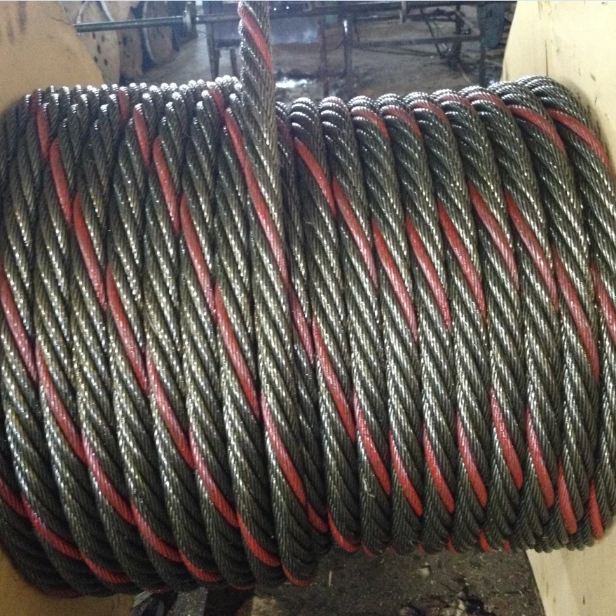
Rope Services Direct supplies a variety of anti-spin non rotating wire rope (also called rotation resistant wire-rope). All standard rope wirehas a tendency to develop torque and therefore prone to rotation, whereas non-rotating wire ropes are designed so that the wire-rope outer rotational force naturally counteracts the inner strands rotational force. This is in the event that a rope is subjected to a load.
Rope elongation and rotation occurs on standard ropes when loaded, which can therefore spin the load, quite possibly out of control, which can be dangerous. When the rope rotates in this way the strands will begin to unravel. This causes the rope to lose strength and will undoubtedly fail, which could be catastrophic. It is for these reasons that non rotating wire rope is commonly used for many types of lifting applications including main hoist rope, whip rope,crane rope, off-shore and deck rope and more.
Non rotating wire rope or rotation resistant wire rope has a different construction to standard. as wires and strands are not laid in the same direction like they would be on standard rope. Inner and outer strands of wires are laid in opposite directions. For example the inner may be constructed in left hand lay whilst the outer layer is in right hand lay. The nature of this construction means that torsional forces on the inner and outer wires/strands will counteract each other and therefore minimising the risk of unraveling.
It is worth noting that the number of strand layers will have an effect of the resistance of rotation. A 2 layer rope has less resistance than a 3 layer rope. Therefore the more layers the rope has the greater rotation resistance it will have.
These types of ropes can be classified as spin resistant, rotation resistant or non rotation resistant. Classed on the basis of the number of rotations a certain length of rope does when a force of 20% of the MBF is applied; with 1 turn or less the rope will be classified as non rotating; with rotations between 1 & 4 the rope is classed as low rotation and for rotations between 4 & 10 the rope will be classified as spin resistant, any higher and the rope is NOT rotation resistant at all.
Correct usage and care with handling will prolong the working life. This is due to the friction on the inner wires caused by the strand crossover’s which will eventually cause the inner wires to break up. This is more apparent on non rotating wire rope with two layers. Ropes with 3 or more strand layers will distribute the radial pressures more evenly. Which will reduce friction and stress on the inner wires.
Regular,thorough inspectionsof non rotating rope are essential due to the fact that it is the inner strands that often break first and broken internal wires often go unnoticed as they are difficult to see.Rope Services Direct offer inspectionson all rope with certification issued on completion.
Holding both ends of the rope will prevent unraveling. Correctly fitted terminations will help to prevent damage. Kinking and unraveling may occur and they can also have an effect on the rotational balance if not fitted correctly.


 8613371530291