
wire rope construction types free sample
Wire rope and cable are each considered a “machine”. The configuration and method of manufacture combined with the proper selection of material when designed for a specific purpose enables a wire rope or cable to transmit forces, motion and energy in some predetermined manner and to some desired end.
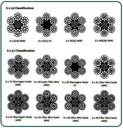
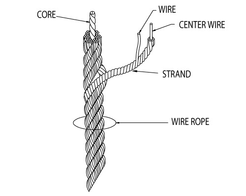
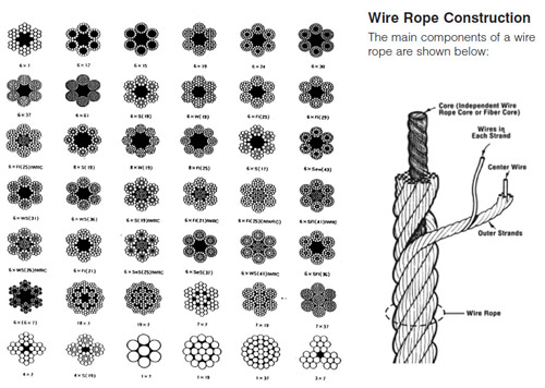
Two or more wires concentrically laid around a center wire is called a strand. It may consist of one or more layers. Typically, the number of wires in a strand is 7, 19 or 37. A group of strands laid around a core would be called a cable or wire rope. In terms of product designation, 7 strands with 19 wires in each strand would be a 7×19 cable: 7 strands with 7 wires in each strand would be a 7×7 cable.
Materials Different applications for wire rope present varying demands for strength, abrasion and corrosion resistance. In order to meet these requirements, wire rope is produced in a number of different materials.
Stainless Steel This is used where corrosion is a prime factor and the cost increase warrants its use. The 18% chromium, 8% nickel alloy known as type 302 is the most common grade accepted due to both corrosion resistance and high strength. Other types frequently used in wire rope are 304, 305, 316 and 321, each having its specific advantage over the other. Type 305 is used where non-magnetic properties are required, however, there is a slight loss of strength.
Galvanized Carbon Steel This is used where strength is a prime factor and corrosion resistance is not great enough to require the use of stainless steel. The lower cost is usually a consideration in the selection of galvanized carbon steel. Wires used in these wire ropes are individually coated with a layer of zinc which offers a good measure of protection from corrosive elements.
Cable Construction The greater the number of wires in a strand or cable of a given diameter, the more flexibility it has. A 1×7 or a 1×19 strand, having 7 and 19 wires respectively, is used principally as a fixed member, as a straight linkage, or where flexing is minimal.
Cables designed with 3×7, 7×7 and 7×19 construction provide for increasing degrees of flexibility but decreased abrasion resistance. These designs would be incorporated where continuous flexing is a requirement.
Selecting Wire Rope When selecting a wire rope to give the best service, there are four requirements which should be given consideration. A proper choice is made by correctly estimating the relative importance of these requirements and selecting a rope which has the qualities best suited to withstand the effects of continued use. The rope should possess:Strength sufficient to take care of the maximum load that may be applied, with a proper safety factor.
Strength Wire rope in service is subjected to several kinds of stresses. The stresses most frequently encountered are direct tension, stress due to acceleration, stress due to sudden or shock loads, stress due to bending, and stress resulting from several forces acting at one time. For the most part, these stresses can be converted into terms of simple tension, and a rope of approximately the correct strength can be chosen. As the strength of a wire rope is determined by its, size, grade and construction, these three factors should be considered.
Safety Factors The safety factor is the ratio of the strength of the rope to the working load. A wire rope with a strength of 10,000 pounds and a total working load of 2,000 pounds would be operating with a safety factor of five.
It is not possible to set safety factors for the various types of wire rope using equipment, as this factor can vary with conditions on individual units of equipment.
The proper safety factor depends not only on the loads applied, but also on the speed of operation, shock load applied, the type of fittings used for securing the rope ends, the acceleration and deceleration, the length of rope, the number, size and location of sheaves and drums, the factors causing abrasion and corrosion and the facilities for inspection.
Fatigue Fatigue failure of the wires in a wire rope is the result of the propagation of small cracks under repeated applications of bending loads. It occurs when ropes operate over comparatively small sheaves or drums. The repeated bending of the individual wires, as the rope bends when passing over the sheaves or drums, and the straightening of the individual wires, as the rope leaves the sheaves or drums, causing fatigue. The effect of fatigue on wires is illustrated by bending a wire repeatedly back and forth until it breaks.
The best means of preventing early fatigue of wire ropes is to use sheaves and drums of adequate size. To increase the resistance to fatigue, a rope of more flexible construction should be used, as increased flexibility is secured through the use of smaller wires.
Abrasive Wear The ability of a wire rope to withstand abrasion is determined by the size, the carbon and manganese content, the heat treatment of the outer wires and the construction of the rope. The larger outer wires of the less flexible constructions are better able to withstand abrasion than the finer outer wires of the more flexible ropes. The higher carbon and manganese content and the heat treatment used in producing wire for the stronger ropes, make the higher grade ropes better able to withstand abrasive wear than the lower grade ropes.
Effects of Bending All wire ropes, except stationary ropes used as guys or supports, are subjected to bending around sheaves or drums. The service obtained from wire ropes is, to a large extent, dependent upon the proper choice and location of the sheaves and drums about which it operates.
A wire rope may be considered a machine in which the individual elements (wires and strands) slide upon each other when the rope is bent. Therefore, as a prerequisite to the satisfactory operation of wire rope over sheaves and drums, the rope must be properly lubricated.
Loss of strength due to bending is caused by the inability of the individual strands and wires to adjust themselves to their changed position when the rope is bent. Tests made by the National Institute of Standards and Technology show that the rope strength decreases in a marked degree as the sheave diameter grows smaller with respect to the diameter of the rope. The loss of strength due to bending wire ropes over the sheaves found in common use will not exceed 6% and will usually be about 4%.
The bending of a wire rope is accompanied by readjustment in the positions of the strands and wires and results in actual bending of the wires. Repetitive flexing of the wires develops bending loads which, even though well within the elastic limit of the wires, set up points of stress concentration.
The fatigue effect of bending appears in the form of small cracks in the wires at these over-stressed foci. These cracks propagate under repeated stress cycles, until the remaining sound metal is inadequate to withstand the bending load. This results in broken wires showing no apparent contraction of cross section.
Experience has established the fact that from the service view-point, a very definite relationship exists between the size of the individual outer wires of a wire rope and the size of the sheave or drum about which it operates. Sheaves and drums smaller than 200 times the diameter of the outer wires will cause permanent set in a heavily loaded rope. Good practice requires the use of sheaves and drums with diameters 800 times the diameter of the outer wires in the rope for heavily loaded fast-moving ropes.
It is impossible to give a definite minimum size of sheave or drum about which a wire rope will operate with satisfactory results, because of the other factors affecting the useful life of the rope. If the loads are light or the speed slow, smaller sheaves and drums can be used without causing early fatigue of the wires than if the loads are heavy or the speed is fast. Reverse bends, where a rope is bent in one direction and then in the opposite direction, cause excessive fatigue and should be avoided whenever possible. When a reverse bend is necessary larger sheaves are required than would be the case if the rope were bent in one direction only.
Stretch of Wire Rope The stretch of a wire rope under load is the result of two components: the structural stretch and the elastic stretch. Structural stretch of wire rope is caused by the lengthening of the rope lay, compression of the core and adjustment of the wires and strands to the load placed upon the wire rope. The elastic stretch is caused by elongation of the wires.
The structural stretch varies with the size of core, the lengths of lays and the construction of the rope. This stretch also varies with the loads imposed and the amount of bending to which the rope is subjected. For estimating this stretch the value of one-half percent, or .005 times the length of the rope under load, gives an approximate figure. If loads are light, one-quarter percent or .0025 times the rope length may be used. With heavy loads, this stretch may approach one percent, or .01 times the rope length.
The elastic stretch of a wire rope is directly proportional to the load and the length of rope under load, and inversely proportional to the metallic area and modulus of elasticity. This applies only to loads that do not exceed the elastic limit of a wire rope. The elastic limit of stainless steel wire rope is approximately 60% of its breaking strength and for galvanized ropes it is approximately 50%.
Preformed Wire Ropes Preformed ropes differ from the standard, or non-preformed ropes, in that the individual wires in the strands and the strands in the rope are preformed, or pre-shaped to their proper shape before they are assembled in the finished rope.
This, in turn, results in preformed wire ropes having the following characteristics:They can be cut without the seizings necessary to retain the rope structure of non-preformed ropes.
They are substantially free from liveliness and twisting tendencies. This makes installation and handling easier, and lessens the likelihood of damage to the rope from kinking or fouling. Preforming permits the more general use of Lang lay and wire core constructions.
Removal of internal stresses increase resistance to fatigue from bending. This results in increased service where ability to withstand bending is the important requirement. It also permits the use of ropes with larger outer wires, when increased wear resistance is desired.
Outer wires will wear thinner before breaking, and broken wire ends will not protrude from the rope to injure worker’s hands, to nick and distort adjacent wires, or to wear sheaves and drums. Because of the fact that broken wire ends do not porcupine, they are not as noticeable as they are in non-preformed ropes. This necessitates the use of greater care when inspecting worn preformed ropes, to determine their true condition.
Asteel wire rope is defined not only by its basic elements (wires, strands, core), but also by the way in which the individual wires are laid together to create a strand and the way in which the strands are laid around the core, etc. The steel wire rope’s construction is defined when the following criteria have been determined:
The steel wire rope is designated according to the number of strands, the number of wires in each strand, the design (type) of the strand, and the type of core.
The number of wires in a strand varies between three and approx. 139, although there are most commonly 7, 19, 24 or 36 wires. The number of wires and their thickness depend on the design of the strand and affects the characteristic of the steel wire rope.
The type of strand is characterised by the way in which the wires in the strand are arranged. There are four basic types of strand design that are used in all steel wire ropes, either in their original form or as a combination of two or more types. The four basic types are:
The Standard construction (fig. 3) is characterised by the fact that all wires are of equal thickness, although the core wire may be thicker. The wires are also laid together in such a way that all of them, with the exception of the centre wire, are of equal length. In this way all the wires are subjected to an equal distribution of load when pulled straight.
The geometric wire distribution consists of one centre wire, onto which one or more layers are laid. Each layer is produced in a separate operation. If there are several layers, the number of wires increases by six for each layer.
The designation for a Standard strand with e.g. seven wires is (1-6), i.e. one centre wire with six external wires in one operation. If there are 37 wires it is known as (1-6/12/18), i.e. one centre wire with six external wires from the first operation, 12 from the second operation and 18 from the third operation.
The Seale construction (fig. 5) is characterised by the way in which the strand consists of two layers of wire produced in one operation. Also, the number of wires in the first and second layer is identical.This construction is somewhat stiffer than a corresponding Standard construction (with the same number of wires). This is because the outer wires in the Seale construction are considerably thicker.
The Filler construction (fig. 7) is characterised by a strand consisting of two layers of wires produced in one operation. Also, the number of wires in the second layer is twice the number in the first layer. This is, however, only possible if filler wires are inserted between the first and the second layers, to prevent the strand becoming hexagonal in shapes.
This construction is more flexible than a corresponding Standard construction and considerably more flexible than a corresponding Seale construction (with the same number of wires excluding filler wires).
A Filler strand with e.g. 25 wires (including 6 filler wires) is known as (1-6+6F-12), i.e. one centre wire with six wires in the first layer and 12 wires in the second layer. There are six filler wires between the first and the second layers.
The Warrington construction (fig. 9) is characterised by a strand consisting of two layers of wire produced in one operation. The second (outer) layer contains wires of two dimensions, and the number of wires in the second layer is twice the number in the first.
This construction is very compact and flexible. A Warrington strand with e.g. 19 wires is known as (1-6-6+6), i.e. one centre wire with six wires in the first layer and a total of 12 wires of two dimensions in the second layer. The centre wire may be replaced by several wires or a fibre core (fig. 10).
As previously mentioned, there are also strands that are a combination of one or more of the above four basic types of strand. One of these is the Warrington-Seale (fig. 11).
The Warrington-Seale construction is characterised by a strand consisting of three layers of wire produced in one operation. The number of wires in the third (outer) layer matches the number of wires in the second layer. Also, the layers below the outer layer are built as a Warrington construction.
A Warrington-Seale strand with e.g. 36 wires is known as (1-7-7+7-14), i.e. one centre wire with seven wires in the first layer, 14 wires made up of two dimensions in the second layer, and 14 wires in the third layer.
The strands and the wires in the strands do not necessarily have to be round. Examples of this are shown in fig. 12. The strands are special strands (i.a. with profiled wire), designed to meet extremely unusual requirements.
The number of strands in a steel wire rope varies between three and approx. 36, although most commonly there are six strands. The more strands a steel wire rope contains, the more rounded and flexible it is, although the wires in the strand are also thinner (less durable).
Fibre cores are the most commonly used, as not only do they provide a good, elastic base but also enable lubrication of the rope from the inside, since it is possible to add oil and/or grease to the fibre core during production. This reduces the risk of rust attacking from the inside. The fibre core is normally produced from polypropylene (PP) or sisal. PP can withstand weaker acids and alkalis and it does not rot. The advantage of a sisal core is that it can absorb oil/grease to a greater degree for lubrication of the steel wire rope from the inside.
Randers Reb recommends the use of a steel core, in the event that it is not certain that a fibre core will provide satisfactory support for the strands, e.g. if thesteel wire rope is spooled on to a drum in several layers under a considerable load, or at high temperatures.
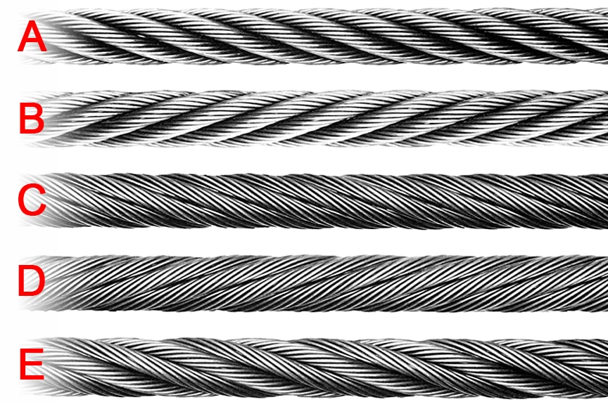
The word “lay” has more than one meaning in this context. It is used to describe the process of interweaving the wires and strands and also to describe the appearance of the finished steel wire rope. The four most common terms to describe the lay of a steel wire rope are:
Right hand regular lay steel wire rope. In this instance the wires in the strand are laid in the opposite direction to the strands in the rope. The wires are laid helically left, while the strands are laid helically right (see fig. 13).
Right hand Lang lay steel wire rope. Here the wires are laid in the same direction as the strands in the rope. The wires in the strands and the strands are laid helically right (see fig. 15).
Multi layer steel wire rope (low rotation/rotation resistant). Here there are usually two layers of strands, the inner layer as a rule a left hand Lang lay, while the outer layer is a right hand regular lay.
Cable laid steel wire rope. The strands are normally 6-lay steel wire rope with a fibre or steel core. The core is a fibre core or a 6-lay steel wire rope with a fibre or steel core.
Flat braided steel wire rope. This steel wire rope is flat braided from strands or consists of parallel strands or steel wire ropes that are bound together by sewing (belt strap).
Right hand lay steel wire rope is also known as Z-lay, and left hand as S-lay. Similarly, a right hand lay strand is known as z-lay and left hand as s-lay. Fig. 17 shows why. Of the types of lay described, right hand regular lay is the most common.
“Preformed” refers to steel wire ropes in which the strands have been permanently formed during the laying process (see fig. 18), so that they are completely stress-free within the unloaded steel wire rope.
All Randers Reb steel wire ropes are supplied preformed, with the exception of certain individual special constructions (e.g. low-rotation/rotation resistant).
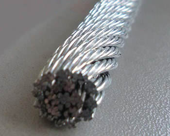
Left hand lay or right hand lay describe the manner in which the strands are laid to form the rope. To determine the lay of strands in the rope, a viewer looks at the rope as it points away from them. If the strands appear to turn in a clockwise direction, or like a right-hand thread, as the strands progress away from the viewer, the rope has a right hand lay. The picture of steel wire rope on this page shows a rope with right hand lay. If the strands appear to turn in an anti-clockwise direction, or like a left-hand thread, as the strands progress away from the viewer, the rope has a left hand lay. (The rope in the left hand lay photo shows one left hand lay rope from left to right and top to bottom, with 5 right hand lay strands, and part of a sixth in the upper left. It is not 5 right hand lay ropes adjacent to each other.)
Ordinary and Ducay"s lay describe the manner in which the wires are laid to form a strand of the wire rope. To determine which has been used, first identify if left or right hand lay has been used to make the rope. Then identify if a right or left hand lay has been used to twist the wires in each strand. (On ordinary lay, the outer wires approximately follow the alignment of the rope: with Lang"s lay they are cross at an angle of about 45�.) Lang"s laid rope is able to flex over sheaves more easily (with less damage) but it has the disadvantage of having a high torque tendency (it tends to untwist when tension load is applied) compared with ordinary laid rope. Untwisting can be dangerous with a steel-cored rope: load is shed from the strands and may cause the core to fail as it becomes higher loaded. For this reason, swivel termination units can be dangerous.
The specification of a wire rope type � including the number of wires per strand, the number of strands, and the lay of the rope � is documented using a commonly accepted coding system, consisting of a number of abbreviations.

Rotation resistant wire rope refers to a series of steel ropes which minimizes the tendency to spin or rotation under load. These wire ropes boast special design - the outer layer is twisted in the reverse direction of inner layers for counteracting torsional forces generated from multi-layers of strands.
To achieve the resistance against the spin and rotation, all wire ropes are composed of at least two layers of strands. In general, more layers a rotation resistant wire rope has, more resistance it will boast. For example, 2-layer ropes is much easier to spin and rotate than 3-layer ones. Meanwhile, if one end of free rotation is allowed, 2-layer rope can only develop 55% to 75% of its breaking strength comparing with 95% to 100% of 3-layer ropes.
The 3-layer rope with more outer strands is capable to distribute more radial pressure onto inner layers and ideal for larger mobile such as all tower cranes.
Wire ropes with 8 to 10 strands & 2-layer constructions without reversely twisted inner strands have very similar appearance to rotation resistant wire ropes, but they are not.
Rotation resistant wire ropes are considered to be less stable needing to be handled and installed with great care. They must be taken to avoid high loads with small diameter sheaves.
Understanding the basics of wire rope will help guide you on how to choose the right wire rope for your job. Application, required strength, and environmental conditions all play a factor in determining the type of wire rope that is best for you.
But when it comes to buying wire rope, the various numbers and abbreviations that describe the different types of wire rope can be confusing. EIPS wire rope, 6X19 IWRC wire rope, and lang lay wire rope are just some of the many variations available. But what does it all mean?
Displayed as inch or fractional inch measurements, the size indicates the diameter of the rope. Industry standards measure the rope at its widest point. A wide range of sizes are available from 1/8” wire rope to 2-1/2” wire rope. Thicker sized wire rope has a higher break strength. For example, our Wire Rope has a 15,100 lb. break strength while our Wire Rope has a 228,000 lb. break strength.
The numbers indicate its construction. For example: in wire rope, as shown above the first number is the number of strands (6); the second number is how many wires make up one strand (19).
When it comes to wire rope basics, regular lay also refers to right lay or ordinary lay. This indicates that the strands pass from left to right across the rope and the wires in the rope lay in opposite direction to the lay of the strands. This type of construction is the most common and offers the widest range of applications for the rope.
This term indicates that the wires twist in the same direction as the strands. These ropes are generally more flexible and have increased wearing surface per wire than right lay ropes. Because the outside wires lie at an angle to the rope’s axis, internal stress is reduced making it more resistant to fatigue from bending. This type of rope is often used in construction, excavating, and mining applications.
Independent wire rope cores offer more support to the outer strands and have a higher resistance to crushing and heat. Independent wire rope core also has less stretch and more strength.
Many of our customers use our rope and our wire rope clips to create rope assemblies. Check out of video blog on Wire Rope Clips to Wire Rope Assemblies to learn more.
For any questions on our wire rope products, call (877) 923-0349 or email customerservice@uscargocontrol.com to speak with one of our product experts.
Early tower installations for radio broadcasting offered problems similar to those met in guying stacks, poles, derricks and similar structures. Guys for these moderate-height structures were commonly made of regular wire rope.
Structural strand is now used for guy systems. Where larger diameter wire rope was once used, structural strand, with its higher modulus of elasticity and lower diameter-to-strength ratio, allows for smaller diameter guys. This reduction in diameter reduces ice and wind loads, which may be important in the overall design of the tower. Structural strand’s higher modulus of elasticity (less stretch) also allows for less take-up of the bolts during tensioning.
Uniformity in tensioning and deflection is necessary for tower guys. Therefore, it is important that the structural strand guys have minimal constructional stretch, a high modulus of elasticity and accurate length measurements. Pre-stretching the strand eliminates most of the constructional stretch and contributes to the strand’s high modulus of elasticity. Proof loading may be used to prove the security of end attachments. Field tensioning of the guys is facilitated by our ability to supply precisely measured and completely documented strand assemblies.
When appearance, durability, utility and ease of construction are considered, suspension bridges are often the most economical to build. For example, flood damage to exposed piers is eliminated and difficult or dangerous pier foundations can be avoidedwith a suspension-cable construction. Often the entire problem area is spanned; the foundations can be located at economical installation points where they are least likely to be damaged. Great clearance is obtained since the supporting structure is above the floor and has no intermediate supports.
Structural strand and wire rope is used for the main cables, suspenders and wind cables of highway, pedestrian and pipeline suspension bridges. Structural strand is manufactured through 5 1/2” diameter and wire rope up to 7” diameter.
Pre-stretching greatly reduces the constructional stretch ofthe structural strand or wire rope and improves the overall elastic stability. While in the pre-stretcher, overall lengths and intermediate tower and suspender points can be measured to close tolerances under prescribed tensions.
In a tied arch bridge, the bridge deck is suspended by structural strand or wire rope hangers hung from a steel or concrete arch. Tied arch bridges normally cross short to medium spans. Structural strand has been used in tied arch bridges having span lengths of more than 1,000 feet.
Galvanized helical structural strand has been specified for cable stays as have several other cable configurations. Various types of socket attachment and corrosion protection systems have been used with varying degrees of success. Zinc-poured attachment of sockets is recommended. Corrosion protection systems are too varied and rapidly evolving to recommend a particular system.
Each corner of the span is connected to the counterweights by sets of large wire ropes which operate over parallel-grooved sheaves at the top of the towers. Using powered winch drums, smaller wire ropes raise and lower the movable span.
The lengths of the counterweight ropes in each of the four corners must be matched closely to ensure equalization of tension. Uniform stretch also is an important factor. In vertical lift bridges where counterweight clearances are limited, ropes should have minimal constructional stretch. Counterweight ropes can be pre-stretched to reduce constructional stretch, and measured under tension to ensure closer control of rope lengths. Normally, operating ropes do not require pre-stretching since minor length adjustments can be made at the drums.
In recent years, design and construction of structures with cable-supported and cable-suspended roofs has increased. As opposed to other methods, cable roof structures permit economical, column-free construction over large spans. Cable roofs also decrease the stresses on the superstructure, supporting members and the foundation, thereby permitting the use of fewer and lighter materials. Cable roofs offer a bold challenge to architects and structural engineers who seek new ways to utilize interesting techniques and materials.
The architectural forms of suspension roofs are numerous. If adequately treated in the conceptual design stage, structural suspension systems offer numerous architectural forms, not only for roofs, but for the entire building. The following are the most common types of suspension roofs.
A properly damped, suspension system, consisting of cables designed to resist all superimposed static loads, may be covered with a light roofing material.
Rope Services Direct supplies a variety of anti-spin non rotating wire rope (also called rotation resistant wire-rope). All standard rope wirehas a tendency to develop torque and therefore prone to rotation, whereas non-rotating wire ropes are designed so that the wire-rope outer rotational force naturally counteracts the inner strands rotational force. This is in the event that a rope is subjected to a load.
Rope elongation and rotation occurs on standard ropes when loaded, which can therefore spin the load, quite possibly out of control, which can be dangerous. When the rope rotates in this way the strands will begin to unravel. This causes the rope to lose strength and will undoubtedly fail, which could be catastrophic. It is for these reasons that non rotating wire rope is commonly used for many types of lifting applications including main hoist rope, whip rope,crane rope, off-shore and deck rope and more.
Non rotating wire rope or rotation resistant wire rope has a different construction to standard. as wires and strands are not laid in the same direction like they would be on standard rope. Inner and outer strands of wires are laid in opposite directions. For example the inner may be constructed in left hand lay whilst the outer layer is in right hand lay. The nature of this construction means that torsional forces on the inner and outer wires/strands will counteract each other and therefore minimising the risk of unraveling.
It is worth noting that the number of strand layers will have an effect of the resistance of rotation. A 2 layer rope has less resistance than a 3 layer rope. Therefore the more layers the rope has the greater rotation resistance it will have.
These types of ropes can be classified as spin resistant, rotation resistant or non rotation resistant. Classed on the basis of the number of rotations a certain length of rope does when a force of 20% of the MBF is applied; with 1 turn or less the rope will be classified as non rotating; with rotations between 1 & 4 the rope is classed as low rotation and for rotations between 4 & 10 the rope will be classified as spin resistant, any higher and the rope is NOT rotation resistant at all.
Correct usage and care with handling will prolong the working life. This is due to the friction on the inner wires caused by the strand crossover’s which will eventually cause the inner wires to break up. This is more apparent on non rotating wire rope with two layers. Ropes with 3 or more strand layers will distribute the radial pressures more evenly. Which will reduce friction and stress on the inner wires.
Regular,thorough inspectionsof non rotating rope are essential due to the fact that it is the inner strands that often break first and broken internal wires often go unnoticed as they are difficult to see.Rope Services Direct offer inspectionson all rope with certification issued on completion.
Holding both ends of the rope will prevent unraveling. Correctly fitted terminations will help to prevent damage. Kinking and unraveling may occur and they can also have an effect on the rotational balance if not fitted correctly.
Wire rope is a complex mechanical device that has many moving parts, all working in tandem to help support and move an object or load. In the lifting and rigging industries, wire rope is attached to a crane or hoist and fitted with swivels, shackles or hooks to attach to a load and move it in a controlled matter. It can also be used to lift and lower elevators, or as a means of support for suspension bridges or towers.
A wire rope is a machine with many moving parts. It has a unique design consisting of steel wires that form individual strands laid in a helical pattern around a center core.
Wire rope is a preferred lifting device for many reasons. Its unique design consists of multiple steel wires that form individual strands laid in a helical pattern around a core. This structure provides strength, flexibility and the ability to handle bending stresses. Different configurations of the material, wire, and strand structure will provide different benefits for the specific lifting application, including:
However, selecting the proper wire rope for your lifting application requires some careful thought. Our goal is to help you understand the components of a wire rope, the construction of wire rope and the different types of wire rope and what they might be used for. This will allow you to select the best performing and longest-lasting wire rope for the job at hand.
A finished wire rope is comprised of individual wires, which make up individual strands, which are then laid in a helical pattern around a synthetic or steel core.
A wire rope is a machine with many moving parts. From childhood, many of us have been conditioned to think of a machine as some device with gears, shafts, belts, cams and assorted whirring parts. Yet, by the rules of physics, an ordinary pry bar is a simple machine, even though it has only one part.
A wire rope is, in reality, a very complicated machine. A typical 6 by 25 rope has 150 wires in its outer strands, all of which move independently and together in a very complicated pattern around the core as the rope bends. Clearances between wires and strands are balanced when a rope is designed so that proper bearing clearances will exist to permit internal movement and adjustment of wires and strands when the rope has to bend. These clearances will vary as bending occurs, but are of the same range as the clearances found in automobile engine bearings.
Understanding and accepting the “machine idea” gives a rope user a greater respect for rope, and enables them to obtain better performance and longer useful life from rope applications. Wire rope is a complex piece of mechanical machinery with a number of different specifications and properties that can affect its performance and service life.
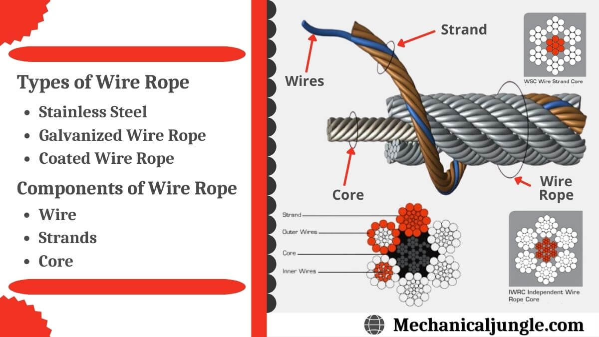
A finished wire rope is comprised of individual wires, which make up individual strands, which are then laid in a helical pattern around a synthetic or steel core. There are four basic components that make up the design of a finished wire rope:
Wires are the smallest component of wire rope and they make up the individual strands in the rope. Wires can be made from a variety of metal materials including steel, iron, stainless steel, monel, and bronze. The wires can be manufactured in a variety of grades that relate to the strength, resistance to wear, fatigue resistance, corrosion resistance, and curve of the wire rope.
Strands of wire rope consist of two or more wires arranged and twisted in a specific arrangement. The individual strands are then laid in a helical pattern around the core of the rope. Strands made of larger diameter wires are more resistant to abrasion, while strands made of smaller diameter wires are more flexible.
The core of a wire rope runs through the center of the rope and supports the strands and helps to maintain their relative position under loading and bending stresses. Cores can be made from a number of different materials including natural or synthetic fibers and steel.
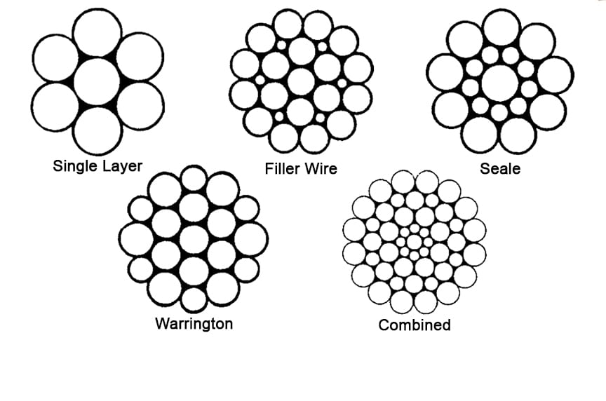
The construction of wire rope falls into one of these strand pattern classifications. The number of layers of wires, the number of wires per layer, and the size of the wires per layer all affect the strand pattern type. Wire rope can be constructed using one of the following patterns, or can be constructed using two or more of the patterns below.
Filler Wire – Two layers of uniform-size wire around a center with the inner layer having half the number of wires as the outer layer. Small filler wires, equal to the number in the inner layer, are laid in valleys of the inner wire.
Seale – Two layers of wires around a center with the same number of wires in each layer. All wires in each layer are the same diameter. The large outer wires rest in the valleys between the smaller inner wires.
Warrington – Two layers of wires around a center with one diameter of wire in the inner layer, and two diameters of wire alternating large and small in the outer later. The larger outer-layer wires rest in the valleys,and the smaller ones on the crowns of the inner layer.
Remember, wire rope is a complex piece of mechanical machinery. There are a number of different specifications and properties that can affect the performance and service life of wire rope. Consider the following when specifying the best type of wire rope for your lifting application:
When you select a piece of rope that is resistant to one property, you will most likely have a trade-off that affects another property. For example, a fiber core rope will be more flexible, but may have less crushing resistance. A rope with larger diameter wires will be more abrasion resistant, but will offer less fatigue resistance.
A rope with larger diameter wires will be more crush resistant and abrasion resistant, while a rope with smaller diameter wires will be more bendable and fatigue resistant.
On a preformed wire rope, the strands and wires are formed during the manufacturing process to the helical shape that they will take in a finished wire rope. Preformed rope can be advantageous in certain applications where it needs to spool more uniformly on a drum, needs greater flexibility, or requires more fatigue-resistance when bending.
Direction and type of lay refer to the way the wires are laid to form a strand (either right or left) and how the strands are laid around the core (regular lay, lang lay, or alternate lay).
Regular Lay – The wires line up with the axis of the rope. The direction of the wire lay in the strand is opposite to the direction of the strand lay. Regular lay ropes are more resistant to crushing forces, are more naturally rotation-resistant, and also spool better in a drum than lang lay ropes.
Lang Lay – The wires form an angle with the axis of the rope. The wire lay and strand lay around the core in the same direction. Lang Lay ropes have a greater fatigue-resistance and are more resistant to abrasion.
A steel core can be an independent wire rope or an individual strand. Steel cores are best suited for applications where a fiber core may not provide adequate support, or in an operating environment where temperatures could exceed 180° F.
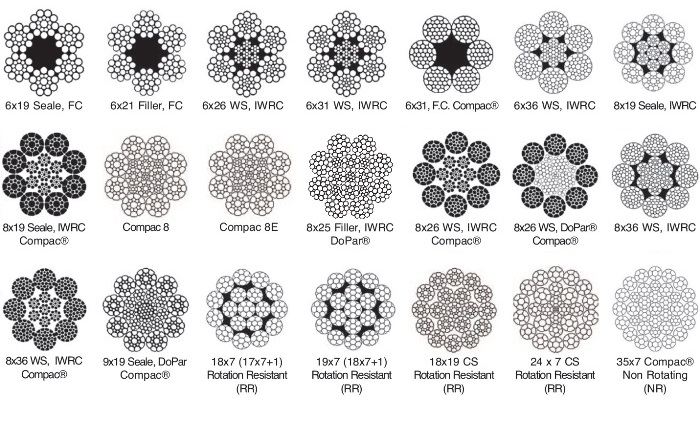
The classifications of wire rope provide the total number of strands, as well as a nominal or exact number of wires in each strand. These are general classifications and may or may not reflect the actual construction of the strands. However, all wire ropes of the same size and wire grade in each classification will have the same strength and weight ratings and usually the same pricing.
Some types of wire rope, especially lang lay wire rope, are more susceptible to rotation when under load. Rotation resistant wire rope is designed to resist twisting, spinning, or rotating and can be used in a single line or multi-part system. Special care must be taken when handling, unreeling, and installing rotation resistant wire rope. Improper handling or spooling can introduce twist into the rope which can cause uncontrolled rotation.
Compacted strand wire rope is manufactured using strands that have been compacted, reducing the outer diameter of the entire strand, by means of passing through a die or rollers. This process occurs prior to closing of the rope.This process flattens the surface of the outer wires in the strand, but also increases the density of the strand. This results in a smoother outer surface and increases the strength compared to comparable round wire rope (comparing same diameter and classification), while also helping to extend the surface life due to increased wear resistance.
A swaged wire rope differs from a compacted strand wire rope, in that a swaged wire rope’s diameter is compacted, or reduced, by a rotary swager machine after the wire rope has been closed. A swaged wire rope can be manufactured using round or compacted strands.The advantages of a swaged wire rope are that they are more resistant to wear, have better crushing resistance, and high strength compared to a round strand wire rope of equal diameter and classification. However, a swaged wire rope may have less bending fatigue resistance.
A plastic coating can be applied to the exterior surface of a wire rope to provide protection against abrasion, wear, and other environmental factors that may cause corrosion. However, because you can’t see the individual strands and wires underneath the plastic coating, they can be difficult to inspect.
Plastic filled wire ropes are impregnated with a matrix of plastic where the internal spaces between the strands and wires are filled. Plastic filling helps to improve bending fatigue by reducing the wear internally and externally. Plastic filled wire ropes are used for demanding lifting applications.
This type of wire rope uses an Independent Wire Rope Core (IWRC) that is either filled with plastic or coated in plastic to reduce internal wear and increase bending fatigue life.
In stricter senses, the term wire rope refers to a diameter larger than 9.5 mm (3⁄8 in), with smaller gauges designated cable or cords.wrought iron wires were used, but today steel is the main material used for wire ropes.
Historically, wire rope evolved from wrought iron chains, which had a record of mechanical failure. While flaws in chain links or solid steel bars can lead to catastrophic failure, flaws in the wires making up a steel cable are less critical as the other wires easily take up the load. While friction between the individual wires and strands causes wear over the life of the rope, it also helps to compensate for minor failures in the short run.
Wire ropes were developed starting with mining hoist applications in the 1830s. Wire ropes are used dynamically for lifting and hoisting in cranes and elevators, and for transmission of mechanical power. Wire rope is also used to transmit force in mechanisms, such as a Bowden cable or the control surfaces of an airplane connected to levers and pedals in the cockpit. Only aircraft cables have WSC (wire strand core). Also, aircraft cables are available in smaller diameters than wire rope. For example, aircraft cables are available in 1.2 mm (3⁄64 in) diameter while most wire ropes begin at a 6.4 mm (1⁄4 in) diameter.suspension bridges or as guy wires to support towers. An aerial tramway relies on wire rope to support and move cargo overhead.
Modern wire rope was invented by the German mining engineer Wilhelm Albert in the years between 1831 and 1834 for use in mining in the Harz Mountains in Clausthal, Lower Saxony, Germany.chains, such as had been used before.
Wilhelm Albert"s first ropes consisted of three strands consisting of four wires each. In 1840, Scotsman Robert Stirling Newall improved the process further.John A. Roebling, starting in 1841suspension bridge building. Roebling introduced a number of innovations in the design, materials and manufacture of wire rope. Ever with an ear to technology developments in mining and railroading, Josiah White and Erskine Hazard, principal ownersLehigh Coal & Navigation Company (LC&N Co.) — as they had with the first blast furnaces in the Lehigh Valley — built a Wire Rope factory in Mauch Chunk,Pennsylvania in 1848, which provided lift cables for the Ashley Planes project, then the back track planes of the Summit Hill & Mauch Chunk Railroad, improving its attractiveness as a premier tourism destination, and vastly improving the throughput of the coal capacity since return of cars dropped from nearly four hours to less than 20 minutes. The decades were witness to a burgeoning increase in deep shaft mining in both Europe and North America as surface mineral deposits were exhausted and miners had to chase layers along inclined layers. The era was early in railroad development and steam engines lacked sufficient tractive effort to climb steep slopes, so incline plane railways were common. This pushed development of cable hoists rapidly in the United States as surface deposits in the Anthracite Coal Region north and south dove deeper every year, and even the rich deposits in the Panther Creek Valley required LC&N Co. to drive their first shafts into lower slopes beginning Lansford and its Schuylkill County twin-town Coaldale.
The German engineering firm of Adolf Bleichert & Co. was founded in 1874 and began to build bicable aerial tramways for mining in the Ruhr Valley. With important patents, and dozens of working systems in Europe, Bleichert dominated the global industry, later licensing its designs and manufacturing techniques to Trenton Iron Works, New Jersey, USA which built systems across America. Adolf Bleichert & Co. went on to build hundreds of aerial tramways around the world: from Alaska to Argentina, Australia and Spitsbergen. The Bleichert company also built hundreds of aerial tramways for both the Imperial German Army and the Wehrmacht.
In the last half of the 19th century, wire rope systems were used as a means of transmitting mechanical powercable cars. Wire rope systems cost one-tenth as much and had lower friction losses than line shafts. Because of these advantages, wire rope systems were used to transmit power for a distance of a few miles or kilometers.
Steel wires for wire ropes are normally made of non-alloy carbon steel with a carbon content of 0.4 to 0.95%. The very high strength of the rope wires enables wire ropes to support large tensile forces and to run over sheaves with relatively small diameters.
In the mostly used parallel lay strands, the lay length of all the wire layers is equal and the wires of any two superimposed layers are parallel, resulting in linear contact. The wire of the outer layer is supported by two wires of the inner layer. These wires are neighbors along the whole length of the strand. Parallel lay strands are made in one operation. The endurance of wire ropes with this kind of strand is always much greater than of those (seldom used) with cross lay strands. Parallel lay strands with two wire layers have the construction Filler, Seale or Warrington.
In principle, spiral ropes are round strands as they have an assembly of layers of wires laid helically over a centre with at least one layer of wires being laid in the opposite direction to that of the outer layer. Spiral ropes can be dimensioned in such a way that they are non-rotating which means that under tension the rope torque is nearly zero. The open spiral rope consists only of round wires. The half-locked coil rope and the full-locked coil rope always have a centre made of round wires. The locked coil ropes have one or more outer layers of profile wires. They have the advantage that their construction prevents the penetration of dirt and water to a greater extent and it also protects them from loss of lubricant. In addition, they have one further very important advantage as the ends of a broken outer wire cannot leave the rope if it has the proper dimensions.
Stranded ropes are an assembly of several strands laid helically in one or more layers around a core. This core can be one of three types. The first is a fiber core, made up of synthetic material or natural fibers like sisal. Synthetic fibers are stronger and more uniform but cannot absorb much lubricant. Natural fibers can absorb up to 15% of their weight in lubricant and so protect the inner wires much better from corrosion than synthetic fibers do. Fiber cores are the most flexible and elastic, but have the downside of getting crushed easily. The second type, wire strand core, is made up of one additional strand of wire, and is typically used for suspension. The third type is independent wire rope core (IWRC), which is the most durable in all types of environments.ordinary lay rope if the lay direction of the wires in the outer strands is in the opposite direction to the lay of the outer strands themselves. If both the wires in the outer strands and the outer strands themselves have the same lay direction, the rope is called a lang lay rope (from Dutch langslag contrary to kruisslag,Regular lay means the individual wires were wrapped around the centers in one direction and the strands were wrapped around the core in the opposite direction.
Multi-strand ropes are all more or less resistant to rotation and have at least two layers of strands laid helically around a centre. The direction of the outer strands is opposite to that of the underlying strand layers. Ropes with three strand layers can be nearly non-rotating. Ropes with two strand layers are mostly only low-rotating.
Stationary ropes, stay ropes (spiral ropes, mostly full-locked) have to carry tensile forces and are therefore mainly loaded by static and fluctuating tensile stresses. Ropes used for suspension are often called cables.
Track ropes (full locked ropes) have to act as rails for the rollers of cabins or other loads in aerial ropeways and cable cranes. In contrast to running ropes, track ropes do not take on the curvature of the rollers. Under the roller force, a so-called free bending radius of the rope occurs. This radius increases (and the bending stresses decrease) with the tensile force and decreases with the roller force.
Wire rope slings (stranded ropes) are used to harness various kinds of goods. These slings are stressed by the tensile forces but first of all by bending stresses when bent over the more or less sharp edges of the goods.
Technical regulations apply to the design of rope drives for cranes, elevators, rope ways and mining installations. Factors that are considered in design include:
Donandt force (yielding tensile force for a given bending diameter ratio D/d) - strict limit. The nominal rope tensile force S must be smaller than the Donandt force SD1.
The wire ropes are stressed by fluctuating forces, by wear, by corrosion and in seldom cases by extreme forces. The rope life is finite and the safety is only ensured by inspection for the detection of wire breaks on a reference rope length, of cross-section loss, as well as other failures so that the wire rope can be replaced before a dangerous situation occurs. Installations should be designed to facilitate the inspection of the wire ropes.
Lifting installations for passenger transportation require that a combination of several methods should be used to prevent a car from plunging downwards. Elevators must have redundant bearing ropes and a safety gear. Ropeways and mine hoistings must be permanently supervised by a responsible manager and the rope must be inspected by a magnetic method capable of detecting inner wire breaks.
The end of a wire rope tends to fray readily, and cannot be easily connected to plant and equipment. There are different ways of securing the ends of wire ropes to prevent fraying. The common and useful type of end fitting for a wire rope is to turn the end back to form a loop. The loose end is then fixed back on the wire rope. Termination efficiencies vary from about 70% for a Flemish eye alone; to nearly 90% for a Flemish eye and splice; to 100% for potted ends and swagings.
When the wire rope is terminated with a loop, there is a risk that it will bend too tightly, especially when the loop is connected to a device that concentrates the load on a relatively small area. A thimble can be installed inside the loop to preserve the natural shape of the loop, and protect the cable from pinching and abrading on the inside of the loop. The use of thimbles in loops is industry best practice. The thimble prevents the load from coming into direct contact with the wires.
A wire rope clip, sometimes called a clamp, is used to fix the loose end of the loop back to the wire rope. It usually consists of a U-bolt, a forged saddle, and two nuts. The two layers of wire rope are placed in the U-bolt. The saddle is then fitted to the bolt over the ropes (the saddle includes two holes to fit to the U-bolt). The nuts secure the arrangement in place. Two or more clips are usually used to terminate a wire rope depending on the diameter. As many as eight may be needed for a 2 in (50.8 mm) diameter rope.
The mnemonic "never saddle a dead horse" means that when installing clips, the saddle portion of the assembly is placed on the load-bearing or "live" side, not on the non-load-bearing or "dead" side of the cable. This is to protect the live or stress-bearing end of the rope against crushing and abuse. The flat bearing seat and extended prongs of the body are designed to protect the rope and are always placed against the live end.
An eye splice may be used to terminate the loose end of a wire rope when forming a loop. The strands of the end of a wire rope are unwound a certain distance, then bent around so that the end of the unwrapped length forms an eye. The unwrapped strands are then plaited back into the wire rope, forming the loop, or an eye, called an eye splice.
A Flemish eye, or Dutch Splice, involves unwrapping three strands (the strands need to be next to each other, not alternates) of the wire and keeping them off to one side. The remaining strands are bent around, until the end of the wire meets the "V" where the unwrapping finished, to form the eye. The strands kept to one side are now re-wrapped by wrapping from the end of the wire back to the "V" of the eye. These strands are effectively rewrapped along the wire in the opposite direction to their original lay. When this type of rope splice is used specifically on wire rope, it is called a "Molly Hogan", and, by some, a "Dutch" eye instead of a "Flemish" eye.
Swaging is a method of wire rope termination that refers to the installation technique. The purpose of swaging wire rope fittings is to connect two wire rope ends together, or to otherwise terminate one end of wire rope to something else. A mechanical or hydraulic swager is used to compress and deform the fitting, creating a permanent connection. Threaded studs, ferrules, sockets, and sleeves are examples of different swaged terminations.
A wedge socket termination is useful when the fitting needs to be replaced frequently. For example, if the end of a wire rope is in a high-wear region, the rope may be periodically trimmed, requiring the termination hardware to be removed and reapplied. An example of this is on the ends of the drag ropes on a dragline. The end loop of the wire rope enters a tapered opening in the socket, wrapped around a separate component called the wedge. The arrangement is knocked in place, and load gradually eased onto the rope. As the load increases on the wire rope, the wedge become more secure, gripping the rope tighter.
Poured sockets are used to make a high strength, permanent termination; they are created by inserting the wire rope into the narrow end of a conical cavity which is oriented in-line with the intended direction of strain. The individual wires are splayed out inside the cone or "capel", and the cone is then filled with molten lead-antimony-tin (Pb80Sb15Sn5) solder or "white metal capping",zincpolyester resin compound.
Donald Sayenga. "Modern History of Wire Rope". History of the Atlantic Cable & Submarine Telegraphy (atlantic-cable.com). Archived from the original on 3 February 2014. Retrieved 9 April 2014.
Wire ropes are several strands of metal wire that are twisted into a helix to form a composite rope, known as a laid rope. Large diameter wire rope consists of several strands of rope laid in what is known as cabling. Wire ropes are complex mechanical devices consisting of several moving parts that work together to help support & move an object or load.
In the lifting & rigging industries, wire rope is attached to a crane or hoist & fitted with a swivel, shackle, or hook to attach to a load and move it into a controlled case. It can also be used for lifting and lowering elevators or as a means of support for suspension bridges or towers. Wire rope is a preferred lifting tool for many reasons.
Its unique design consists of several steel wires that form separate strands placed in a helical pattern around a core. These structures provide strength, flexibility, & the ability to handle bending stresses. In the strictest sense, the term wire rope refers to a diameter larger than 3/8 inch (9.52 mm), with a smaller gauge specified cable or cord.
Initially, iron wires were used, but today the main material used for wire ropes is steel. Wire rope is made from cold-drawn wires to increase strength & durability. It may be noted that as its size decreases, the strength of the wire ropes increases.
The various materials used for wire ropes are iron, cast steel, extra strong cast steel, steel, and alloy steel, in order of increasing strength. For some purposes, wire rope can also be made from copper, bronze, aluminum alloys, and stainless steel. Wire ropes were developed in the 1830s with mining hoist applications.
Wire ropes are used in cranes and elevators for dynamic lifting and lifting and for transmission of mechanical power. It is also used to transmit forces to mechanisms, such as Bowden cables or the control surface of an airplane connected to levers and pedals in the cockpit.
Wire rope is made of threads of metal wire that are braided together to form a helix. Due to its heavy, flexible and tough characteristics, as well as being weather- and corrosion-resistant, it is commonly used in the building and construction, engineering, agriculture, aircraft, and marine industries.
Each wire strand bringing equal pressure to the bundle contributes to its strength and flexibility, making it an ideal material for pulleys. In Australia, wire rope was made of iron; Today, the materials used are mainly steel. Different industries use different types of wire ropes.
This is because the suitability of a specific wire rope for an application depends on the design, size, type of braids, and other characteristics. For example, marine-grade 316 wire rope is suitable for a variety of marine applications and settings.
Stainless steel is the standard alloy used in rope and cable. Its resistance to corrosions is much higher than that of galvanized & coated ropes, although there are no differences in strength. Therefore, it is the preferred material uses in marines and water-based salt industries.
It does not readily react to chemicals from food processing, textiles, and photographic settings. Its high resistance to corrosion, heat & cold, and pulp & paper chemicals makes stainless steel wire rope a much-needed material for manufacturing precision instruments, automobiles, fishing vessels, petrochemical equipment, & other fields.
Galvanized wire ropes are also steel wire materials that have undergone a galvanizing process to increase their corrosion resistance. The finished wire is immersed in a zinc bath to coat the product completely, i.e., it is galvanized.
Zinc is used in this process because cathode protection increases the life expectancy of the wire. Although the coating will degrade over time, it is still resistant to rust, corrosion, and other harsh chemicals. Galvanized wire can be found in the industrial and construction sectors as well as in agricultural and DIY projects.
Stainless steel and galvanized wire can be PVC coated with poly-vinyl-chloride or vinyl. Coated wire rope comes in various colors such as clear, black, white, or any other color that is required in various industries. PVC coated wire is flexible, weather-resistant, and very cost-effective.
Nylon-coated wire, although not as flexible as PVC, is abrasion-resistant and ideal for businesses in extremely cold regions. Wire ropes can be assembled to suit specific applications. If you have a project requiring a specific type of wire rope, send us an inquiry, and we’ll send you a special quote.
The wire is the smallest component of wire rope, and they form the individual strands in the rope. Wire can be made from a variety of metal materials, including steel, iron, stainless steel, Monel, and bronze. Wires can be manufactured in varieties of grades that are related to wire rope strength, wear resistance, fatigue resistance, corrosion resistance, and curve.
These strings symbolize the smallest component of a wire rope and are tied together around a core to form complete wire ropes. The wire themselves can be coated but are usually available in “bright” or uncoated finishes.
Wire rope strings form two or more wires wrapped around an axial member in a geometric pattern or in combination with steel wires and other materials. These individual strands are then placed around the core in a helical pattern. Strands represent the major part that serves as the primary load-bearing unit.
A typical strand can form any number of strands, and the same goes for a rope that can have an ‘n’ number of strands. Wires made from larger diameter wires are more resistant to abrasion, while wires made of smaller diameter wires are more flexible.
The core of a wire rope runs through the center of the rope & supports the wires and helps them maintain their relative position under loading and bending stress. Cores can be made from many different materials, including natural or synthetic fibers and steel. It supports the strands and helps maintain their relative position under loading and bending stress.
Wire ropes are made from the various grades of steel wires with tensile strengths ranging from 1200 to 2400 MPa. The wires are first given special heat treatment & then cold drawn for the high strength and durability of the rope. Steel wire ropes are manufactured by special machines.
<


 8613371530291