
wire rope deflection in stock
Look to Enidine for high performance Wire Rope Isolators and Compact Wire Rope Isolators. The wire rope isolators have stainless steel cable and RoHS compliant aluminum retaining bars, which provides excellent vibration isolation. The isolators are corrosion resistant, which makes them environmentally stable and high-performance in a variety of applications. The isolators are completely unaffected by oil, chemicals, abrasives, ozone, and temperature extremes.
The compact wire rope isolator is smaller than a traditional wire rope and can absorb shock and vibration in small spaces. Single point mounting offers flexibility for integration into existing products.
Both compact wire rope isolators and wire rope isolators can be used on galley components where motors and fans produce vibrations onto surrounding structures. They can also be used to control vibration and thermal expansion.
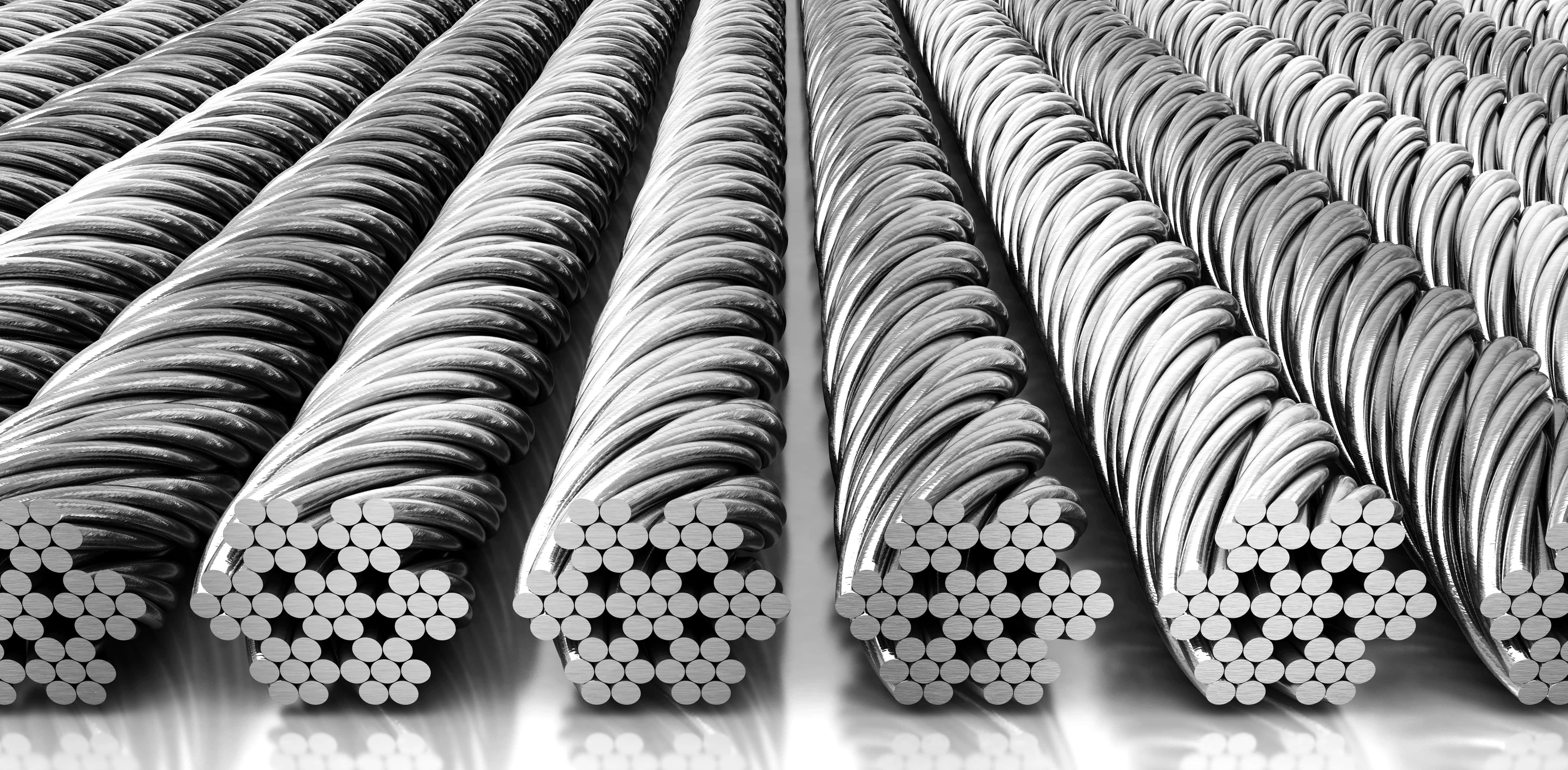
Wire ropes are in widespread use as structural members. A wire rope mostly consists of strands helically twisted around the central core. The strand is constituted of many wires helically wrapped around the inner wire. This implies that the rope geometry can be complicated [1]. Wire ropes are generally used to transmit tensile forces. They have high load-bearing capacities upon relatively small dead weights [2]. Moreover, the rope structure enables the wire ropes to resume loads despite the break of one or more wires [1]. Wire ropes are commonly used in civil and mechanical engineering, e.g., in bridges, cranes, cable cars, mine hoists, elevators, prestressed concrete structures, road safety equipment, and other similar applications [3,4,5,6,7].
Due to the increasing usages of ropes, numerous works investigating their performance have been published. They present, among other aspects, experimental tests [8], numerical tests [9,10], fatigue analysis [11], performances in various environments and conditions, and the behavior of partly damaged [1] or corroded wire ropes [5]. Developing a mathematical model for predicting wire rope responses is challenging due to the complex architecture of ropes, particularly if the effect of contact and frictional forces between wires is to be considered [12]. Most mathematical models are limited to a single, straight strand, where all wound wires are single helices [3,13,14]. However, most actual ropes consist of several or more strands in which most wires are configured as double helices [3,15]. To analyze ropes with a complex topology and to include various factors in calculations, the Finite Element Method (FEM) is increasingly being employed [16,17].
One analytical model was proposed by Costello (1997) [13]. It describes the equilibrium of a single wire, as well as static responses of a single strand and wire rope. Argatov (2011) [3] studied the response of a wire rope strand to axial and torsional loads. The refined discrete mathematical model was developed to correctly assess its deformation, taking into account interwire contacts. This model enables local contact stresses to be obtained. Argatov et al. (2011) [4] studied the wear degradation of wire ropes subjected to cyclic bending over a sheave by applying the Archard–Kragelsky wear law. The proposed mathematical model can be useful for estimating the fatigue life of wire ropes.
Nowadays, numerous research employing numerical simulations is being conducted. FEM simulations make it possible to analyze the response of wire ropes in detail, even for a complicated geometry. The most valuable simulations are those compared and validated against experiments. Generally, numerical models of wire ropes can be divided into 2D (simple) [2] and 3D (more complex) formulations [12,18]. 3D models are more common and universal. These models are usually developed using solid finite elements (FEs) or beam FEs [2]. The simulations, where solid FEs are applied, are high-cost computational methods [2]. There are also so-called mixed models utilizing solid and beam FEs at the same time. For instance, the core can be modeled as solid FEs and the wires as beam FEs [19]. Advanced and detailed 3D models (Figure 1a) are typically used to analyze short sections of ropes because they require much work and computational resources. For analyses of a rope of a considerable length (e.g., several dozen meters, Figure 1b), simplified models are commonly employed [11,20].
Previously, numerical analyses were limited to simple straight strands; currently, they are used to examine geometrically complex ropes. Jiang et al. (2000) [16] developed a numerical model of a wire rope utilizing solid FEs. The elaborated model showed better agreement with the experimental results from the literature than the analytical model proposed by Costello in 1997. Elata et al. (2004) [15] developed a new model for simulating the mechanical response of a wire rope subjected to both an axial load and an axial torque. The model was validated against experimental data collected from the testing of two cables and compared to Velinski’s and Costello’s model. Erdönmez et al. (2009) [21] numerically studied the axial loading and bending of simple strand wire over a sheave. The results showed that the maximum stress occurred over the upper sheave midpoint. Judge et al. (2011) [22] conducted experimental and numerical research on a cable consisting of 120 wires subjected to the impact of a 20-mm fragment with velocities between 200 and 1400 m/s. The numerical simulation showed good agreement with the laboratory tests. Boroška et al. (2014) [23] described the influence of various factors on Young’s modulus of the wire ropes and gave some values. They also numerically investigated the 100-mm long sample and presented the stress distributions within the rope. Wu (2014) [10] developed a numerical model of a wire rope subjected to tensile loads and compared the results to theoretical and experimental data taken from the literature. Foti et al. (2016) [24] investigated the behavior of a strand under axial–torsional loads using a new analytical formulation and FEM simulations. The results were validated against experimental and theoretical results from the literature. The effects of wire lay angles and the torsional boundary were discussed. Karathanasopoulos et al. (2017) [2] proposed a 2D elastoplastic FE model to simulate the behavior of a simple strand. The advantage of this simplified planar model is its robustness and low computational cost. The results were compared with the 3D FE model of Foti et al. [24] and a very good agreement was obtained. Vukelic et al. (2017) [12] numerically investigated the influence of a reduction of the cross-sectional area on stress levels and the remaining fatigue life for three design types of wire ropes. The results showed that the reductions in cross-sectional areas below 90% of the initial area cause a substantial increase in stress levels and significant decreases in the remaining life of the wire ropes. Wang et al. (2017) [17] developed an FE model of wire rope and showed that stresses are unevenly distributed within the rope. They also conducted experimental tensile tests and compared the results with the simulation. The calculations showed good agreement with physical tests. Smyth (2018) [11] analyzed a wire rope used in an overhead crane and, because the actual bending stiffness properties were not known, the author applied data from another wire rope type and appropriately scaled it using the relative stiffness ratios between the ropes. The papers cited above indicate that both theoretical and numerical models still need to be developed, tested, and then refined. It is noteworthy that publications dealing with the bending properties of wire ropes are still limited.
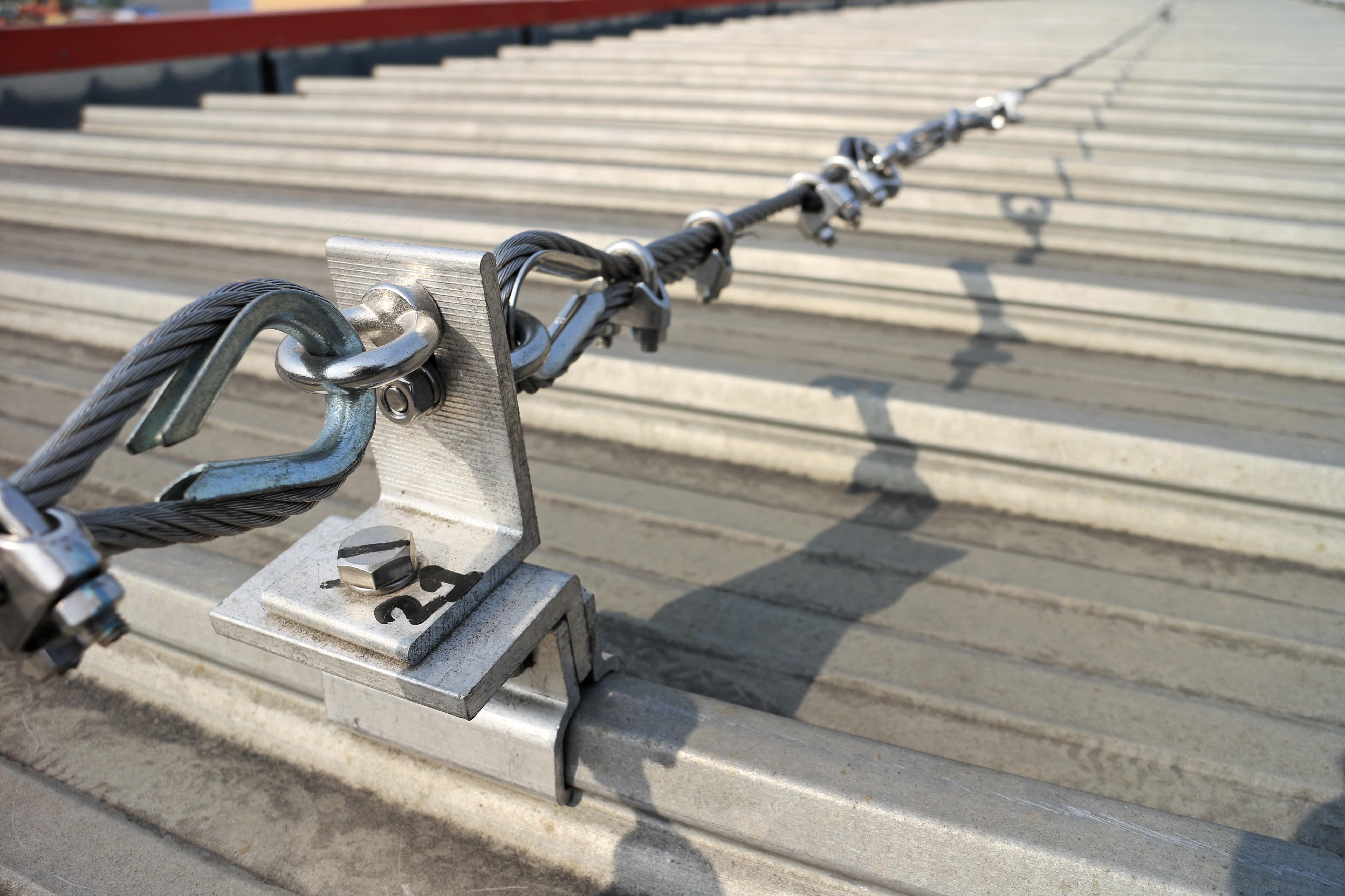
In this paper, the subject of the analysis is a 3 × 7 19-mm wire rope, which is commonly used in road cable barrier systems (Figure 2) [25,26,27]. Descriptions of the cable barrier systems and examples of their use are presented in previous reports [28,29,30,31,32]. Knowledge about this wire rope and its properties is crucial, helping to better understand and analyze vehicular impacts on cable barriers. So far, research has mainly focused on evaluations of the performance of the whole safety system [33,34]. To the best of the author’s knowledge, the only studies on the properties of the 3 × 7 19-mm wire rope have been published by the team led by Reid [20,35,36]. To determine the bending properties, they tested the wire rope in a cantilever position. The longest tested rope was 1.359 m long, and the maximum applied point load was approximately 36.5 N. The physical tests were supplemented with numerical simulations. The rope was modeled in a simplified manner, using only one beam FE in the wire rope cross-section, because these studies were concentrated on the development of a wire rope computational model which can be used in applications of a considerable length. It should be mentioned that in the literature, there are no studies on four-point bending of this rope. Due to the small amount of experimental data and the lack of numerical analyses using advanced 3D models, further research on 3 × 7 19-mm wire rope is desirable.
This work aims to determine the bending properties of the 3 × 7 19-mm wire rope. The main result of the research is the determination of the moment–curvature relationship. The other objectives are to analyze the wire rope behavior under a bending condition, to investigate the interwire contact and to test whether the prestretching affects the rope bending performance. The practical aspects of the article are to determine and explicitly deliver equations for recreating the actual 3D geometry of the rope, to present the methodology of developing advanced numerical rope models, and to give suggestions concerning the use of beam or solid FEs. To achieve the assumed objectives, 19 experimental tests were carried out, which were supported by four nonlinear FEM analyses. With reference to published research on the 3 × 7 19-mm wire rope, this study presents the results of four-point bending tests and the effect of prestretching on the rope bending properties and delivers the equations enabling one to recreate the 3D 3 × 7 wire rope geometry. Furthermore, conducted numerical simulations will supplement knowledge on the contact stress values and their distribution within the rope, as well as the influence of the friction coefficient between the wires on the rope performance. The previous models of this rope, collected and published in [36], do not allow for the analysis of the mentioned issues, as they were developed for a different purpose. This research is important because the wire rope analyzed is used in road cable barriers and its properties affect the effectiveness of the whole safety system, thus affect the safety of vehicle occupants during an accident. Taking into account the small amount of available experimental and numerical data, it is advisable to conduct further studies allowing for a better understanding of the wire rope behavior. This data could potentially give suggestions for the optimization of the 3 × 7 wire rope, for instance, in terms of the dimensions and geometry. The study will also give suggestions for conducting experimental and numerical bending tests for wire ropes. The remainder of this paper is organized as follows: Section 2 describes the characteristics and the geometry of the wire rope; Section 3 presents the moment–curvature relationship from the Bernoulli–Euler beam theory; Section 4 deals with the four-point experimental bending tests, introducing the test stand and specimens and presenting the results; Section 5 shows the computational models developed and an analysis of numerical simulations; in Section 6, the final moment–curvature relationship is proposed and the research is discussed; and Section 7 contains the summary and conclusions.

Function of Head Sheaves device : the Head Sheaves device is used for floor type multi rope friction hoist. Each hoist is installed on the derrick with two groups to change the direction of steel wire rope and adjust the center distance of lifting container according to the requirements of lifting system. It is one of the main bearing parts of the hoist.
Each set is composed of several separate wheels, one of which is connected with the shaft with a flat key, which is called the fixed wheel. When the steel wire rope moves, the fixed wheel drives the fixed wheel to rotate, and the fixed wheel drives the Head Sheaves device shaft to rotate together. The other wheels and the Head Sheaves shaft are swimming, which is called the traveling wheel. Four half bearing shells (copper tiles) are installed between each hub and shaft of the traveling wheel, and there is an axial clearance of 0.2-0.5mm between the four wheels, When the linear speed of each steel wire rope is not exactly the same, the relative rotation between the traveling wheel and the shaft can be free. The rim groove is padded to protect the steel wire rope,
Avoid the friction between the steel wire rope and the cast steel rim of the steel wheel, so as to improve the service life of the steel rope. The rim and hub are steel castings welded with spokes (channel steel). Generally, the wheel of the crown wheel device is integral. The wheel body of the crown wheel device of large elevator can be made into a two-piece split structure, which is called split crown wheel. Both ends are supported on the cast steel bearing seat with spherical centripetal roller bearings.
Function of Deflection Sheaves: the Deflection Sheaves is used for tower multi rope friction hoist. Each hoist is installed on the lower layer of the machine room. Its main function is to adjust the distance between containers according to the requirements of the lifting system, and increase the wrapping angle of steel wire rope on the friction wheel. When the diameter of the friction wheel is larger than the distance between two lifting containers or between the lifting container and the counterweight, in order to move the steel wire ropes on both sides of the friction wheel closer to each other to meet the requirements of the center distance between the two lifting containers, guide wheels need to be installed.
The structure of the Deflection Sheaves is basically the same as that of the head Sheaves device. It is mainly composed of shaft, fixed wheel, traveling wheel, bearing bush, rolling bearing, gasket, bearing seat, bearing beam and other parts. One wheel (fixed wheel) is connected with the shaft with a flat key. When the steel wire rope moves, the fixed wheel drives the fixed wheel to rotate, and the fixed wheel drives the head sheave wheel shaft to rotate together. The other wheels and the shaft of the deflection sheave are sliding, and the wheel hub is embedded with a wear-resistant copper sleeve, The inner diameter of the sleeve is in dynamic fit with the shaft and has relative free rotation with the shaft. It is called traveling wheel. The fixed wheel and traveling wheel are of integral structure and are welded by hub, rim and channel steel spokes. Between the hub and shaft of the traveling wheel, there are four half bearing shells, generally copper tiles. In order to ensure the flexible operation of the wheels, there is an axial clearance of 0.2-0.5mm between the wheels to ensure that the wheels do not interfere with each other when they rotate. When the linear speed of each steel wire rope is not exactly the same, the relative rotation between the traveling wheel and the shaft can be free. The rim groove is equipped with a liner to prevent the friction between the steel wire rope and the rim, so as to prolong the service life of the steel wire rope. Both ends of the shaft adopt spherical centripetal roller bearings.
CIC’s Head Sheaves and Deflection Sheaves come in many sizes to suit whatever size rope you may be using, from 1600mm to 6500mm in diameter. And even if these sizes don’t match your needs, you can have something made to a larger size. Our sheaves are made to withstand a load equal to the breaking strength of the rope, which ensures safe use. In order to best match the conditions of different mine shafts, there are multiple options for the sheaves’ lining. You can order replaceable split wedge-type UHMW liners, or an unlined sheave. If installing in a tight space, sheaves can be designed with split type or segmented construction.

By their nature, wire rope isolators are self-snubbing, fail-safe, and captive to the ultimate limits of the metals. They are insensitive to temperature from cryogenic up to near anneal. They resist most industrial and natural environments. The VMC Group’s manufacturing process is set up to create special winding configurations to customize spring rate and deflection.
The tables referenced are not a substitute for proper analysis of system requirements. The key elements to performing a meaningful selection and analysis are:Payload weight, geometry, center of gravity, isolator location
Quite often, we size the isolation system to do the best job within reasonable size constraints. Any theoretical isolator selection must be reconsidered in light of real-world limitations on equipment sway space and the isolator’s physical size and stability. Some very simple equations are used in selecting wire rope isolators. When considering shock, we use an energy method. We reduce a shock pulse to an equivalent velocity step. For a few typical shock inputs, the velocity steps are as follows:
With the spring rate (K) and dynamic displacement (Dd) established, we can now select an isolator. However, designers should take caution: The spring rates published are average. The placement of the static load on the load-deflection curve modifies the spring rate, available dynamic deflection capability, and cross-axes stability. The load-deflection curves for the principal and cross axes should be requested and considered when making any selection. VMC Group’s modeling software takes both the full third-order curve and damping into account.
Particularly with wire rope isolators, a robust system should be designed such that variances in the effective natural frequency due to dynamic damping do not significantly alter performance in the desired band.
VMC Group pioneered the wire rope isolator more than fifty years ago. Steel wire rope is strong, flexible, and fatigue-resistant because it is made up of many individual strands of high-tensile strength drawn wire. When bent or buckled, it is as much an elastic element as any tempered coil spring or elastomeric mount. Due to frictional forces between the individual strands, wire rope can provide a significant level of dynamic damping — typically 15% to 20% of critical damping. This level of damping makes wire rope isolators attractive for applications that involve sweeps through resonance and transients such as shock.
To create a shock and vibration isolator from wire rope, VMC Group creates buckling elements either in the form of helical loops (Helical Series isolators), or individual arcs (Arch and Circular Arch Series). Like any buckling element, a third-order force-deflection curve results. This can also be called a “softening curve.” Graphically, the curve starts from zero and is nearly linear. As load and deflection increase, the curve eventually begins to flatten. At some further point along the load-deflection curve, it becomes steeper, creating an inherent snubbing effect.
Shock is attenuated by spreading the input energy over time and distance. The flattened section of the curve is excellent for this. The load-deflection curve of a wire rope is very long given the isolator’s physical size. The isolator is a hollow, slender device capable of collapsing in on itself. For its size, it can deflect far more than elastomer and more than a coil spring. This is not to say that wire rope isolators are strictly shock attenuators and not vibration isolators. As an elastic element in a spring-mass system, it will exhibit a natural frequency and thereby form a low-pass filter for vibration energy in the same manner as any coil spring or elastomeric isolator. VMC Group does not list load ratings for individual wire rope isolators and we publish two different average spring rates. We have average static load-deflection curves available in both hard copy and electronic form for the principal isolator directions. They are always available on request. We have also chosen not to include load-deflection curves for wire rope isolators and encourage you to obtain assistance from VMC Group’s Engineering Services Division at 1-800- 569-8423. In almost all cases, application assistance, including analysis and modeling, is performed free of charge and without obligation to the customer.
To determine how much load can be placed on a wire rope isolator, we must first ask what the customer intends to do with the isolator. If small amplitude vibration is the input, we can place the static load along much of the lower two- thirds of a typical load-deflection curve. The effective static spring rate is the tangent of the curve at that load point. If large amplitudes, particularly deep shocks, are to be the input, we place the static load down in the linear first third of the curve. This allows the load to ride high up onto the curve in response to the shock. In this case, the effective average spring rate is a global straight-line, end-to-end slope of the curve over the excursion. To provide average values in the catalog for design purposes, we take the vibration spring rate as the tangent slope near zero and the shock spring rate as the overall end-to-end straight-line slope over the curve. VMC Group’s modeling software takes the entire third-order curve into account. The non-linear nature of the response curve and the presence of input-dependent damping are good reasons to work with our engineering department when selecting an isolator.
Another reason to consult with VMC Group before selecting your wire rope isolators is the interrelationship between the axes of the isolator. Wire rope isolators are elastic elements in all directions simultaneously. This makes them suited for all-attitude and mobile applications and applications that involve complex, off-axis inputs. The physics of the isolator is such that most inputs produce a response with components in more than one direction.
We can manage this characteristic using properly engineered solutions that take all axes into account. It should be noted that use of the tension direction for primary shock attenuation is not recommended. This is due to the predominance of tensile loading within the cable that results in a stiffening curve.
As the world leader in wire rope technology, our custom plate assemblies, and custom-designed isolators have been used in various applications for over 50 years. Whether for avionics and aerospace equipment, electronics apparatus, engine gensets, auxiliary power supplies, or other sensitive equipment requiring isolation, our engineering group will work with you throughout the entire design process to provide the custom solution you require. Our modeling software has an excellent reputation in the industry for its accuracy and will ensure your project is designed correctly from the beginning. Our plate assemblies and custom isolators have been designed to support weights from just a few pounds to over 100,000 pounds and take the form of special length bars, differing diameter wire, and winds, custom rail systems, plate assemblies, trays, and skids. Our helical wire rope isolators have been qualified on numerous military projects requiring the following typical specifications for shock and vibration:

Tyler Madison has earned its position as a leading custom cable manufacturer of wire rope assemblies through its commitment to quality and customer service. The company always carries an extensive inventory of stock components to meet their customers’ simpler needs. But with an extensive background in wire rope design, the company welcomes the opportunity to design, engineer, and manufacture wire rope solutions to perfectly match its customers’ more specific applications.

PersonalWe are on hand to personally guide you through the entire process, we translate the jargon, we recommend what’s best, and we are always here in person. No nonsense, just straight talking people who always exceed expectations through our extensive wire rope knowledge and superior service.


 8613371530291